(Alexa, Evan, Sheila, Nic, Kiwamu)
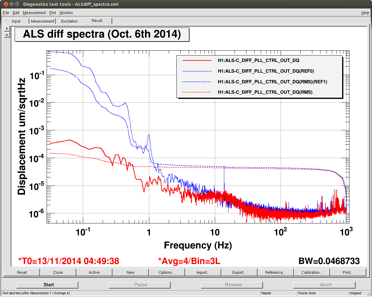
Tonight we locked ALS DIFF with a UGF of 8 Hz, phase margin of 60 deg (2014-11-12-ALS_OLTF.pdf). The in loop noise is 1e-3 um/rtHz RMS down to 0.1 Hz (ALS_Diff_spectra_11122014.pdf). This is comparable to our old ALS_DIFF spectra, which was comparable to HIFOXY days.
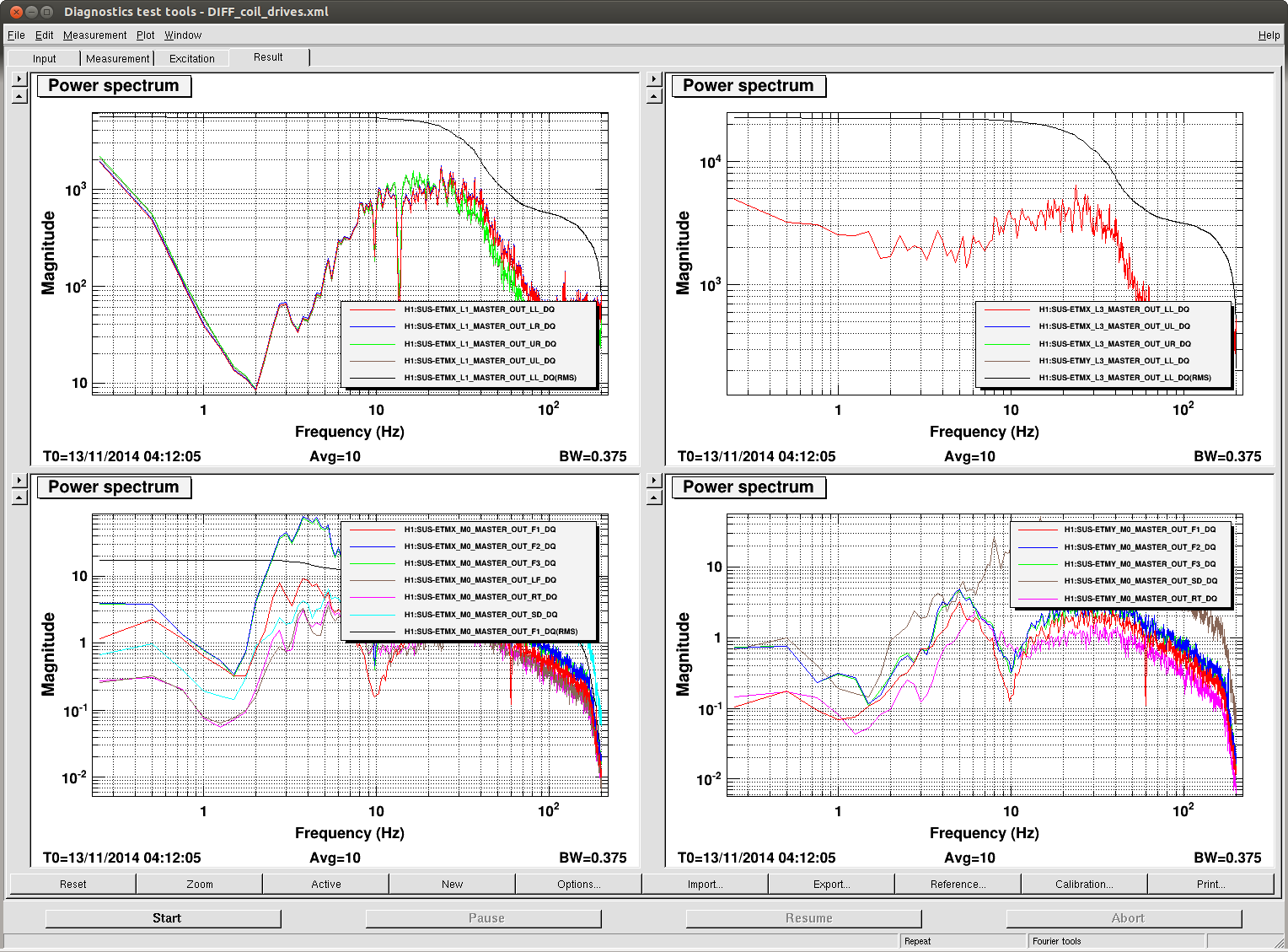
We are running under a similar configuration to LLO. We are using an offloaded distribution for the Quads. Our LSC-DARM and L1_LOCK_L filters are similar to LLO's as described in alog 14961. We have added a resG filter in LSC-DARM to supress noise at 1 Hz and 0.4 Hz. We also added an additional boost in the L1 LOCK L stage to improve our RMS at low frequency. The ESD LOCK L filter was initially empy; however, we added an elliptic filter in L3_LOCK_L to supress noise we saw at around 100 Hz in the ESD coil output, and to reduce the range we use on the ESD coils. The current LSC-DARM filter is shown in LSCDARM_filters.pdf. Meanwhile the L1_LOCK_L filter with the addition of the ESD ellpitcal filter is shown in UIM_filters.pdf.
We have about a factor of 7 headroom in the ESD before we would saturate, and about a factor of 30 head room in the ESD. Tonight the 1-3 Hz seismic is fairly high (0.1 um/sec) but the low frequency is low (0.2 um/sec at 0.1-0.3 Hz). So it seems like we have some room for the seismic to get worse without needing to add the top mass.
Our UIM/ESD crossover is at 0.9 Hz with 50 deg phase margin. The L1_LOCK_L_GAIN = 0.28, L3_LOCK_L_GAIN = 1. We collected data from L1_LOCK_L IN1/IN2 to measure the crossover (UIM_measure_EXonly.pdf). The data is also depicted in DARM_crossovers.pdf; this image also shows the same TF produced by the model along with the UIM/ESD. The model seems to agree with the data well; albeit with a gain of 5 fudge factor. I have also attached the OLTF produced by the model (DARM_TFs.pdf).
We found we could stabily and repeatbly lock ALS DIFF with a LSC-DARM gain of 400. We were ONLY feeding back to EX. We are suspicious of the EY ESD; when we feed back to EY the y-arm eventually drops lock even with a low DARM gain. We did little investigation into this issue.
ALS_DIFF guardian has been updated, and can lock DIFF in this configuration.

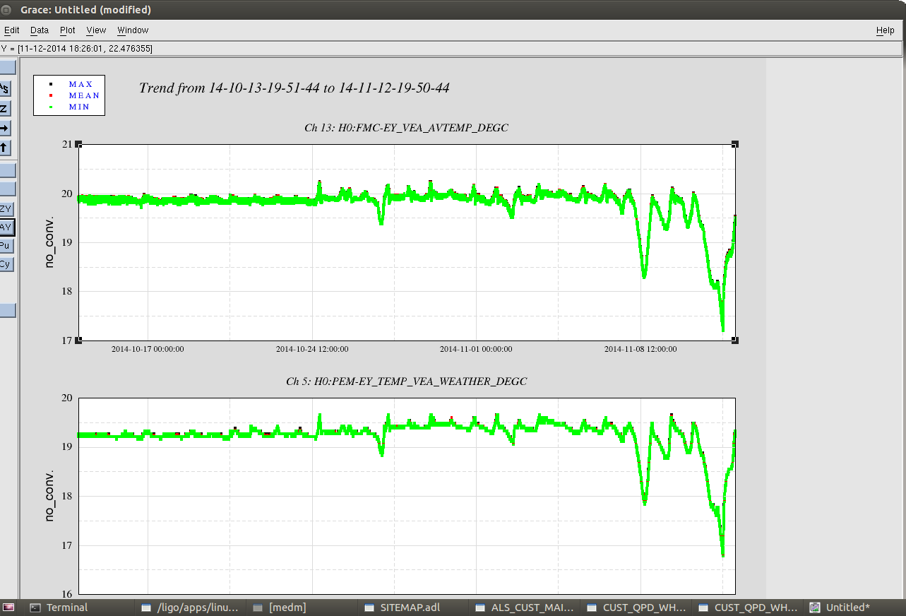

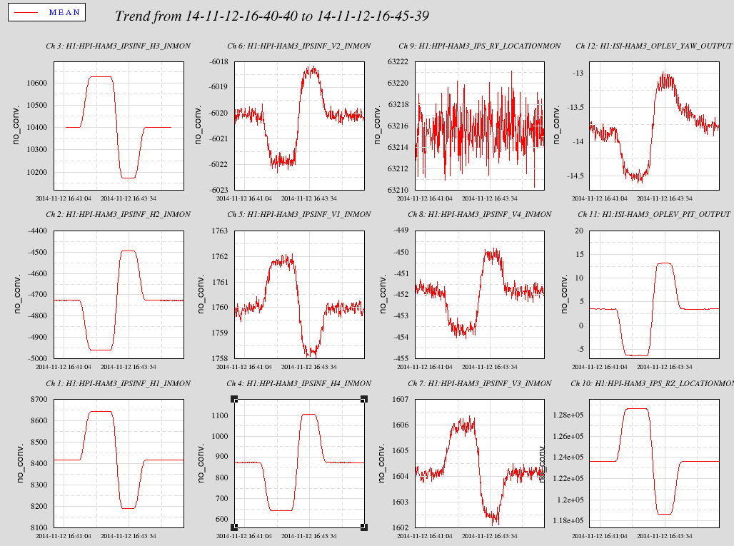
It might be that we've been following the temperature drift in the LVEA. There has been a big downward temperature spike, then the FMCS responded, and totally totally overshot.
In the attached, colored vertical lines indicate Suresh's laser change, Hugh's HAM2 change and commissioners' changing input alignment. From the HAM2 oplev, Hugh's work looks like a minimal impact.
But the time the commissioners responded to whatever change by turning the mirrors corresponds to the temperature change.