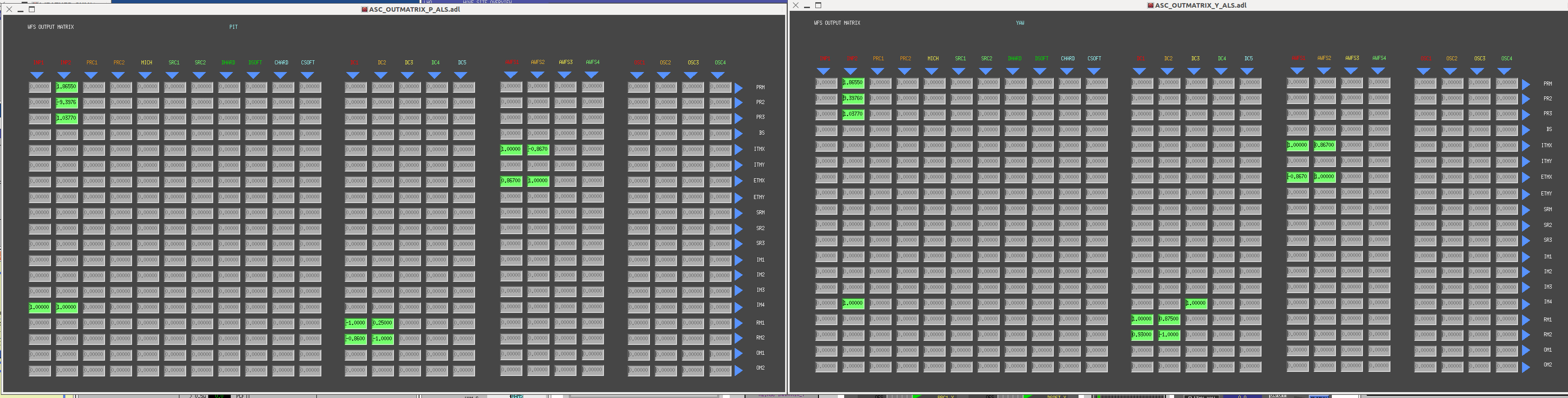
Manually removed oldest frame files to reduce /frames disk usage on tripleteststand, bscteststand2, and seiteststand2. (Routine maintenance)
The report regarding HAM-ISI Unit #5 (HAM3) chamber side testing, and the procedure followed for this phase of testing, are available under the DCC.
This unit is ready for in-chamber installation.
- Terry and Christina finished cleaning HAM5 and HAM6. - Apollo installing cable trays at HAM1 output. - Electrical work for HVAC in LSB fiber bonding lab. - Thomas aligning OpLevs. - BSC1 ICC ongoing. - Gerardo leak-checking BSC6's volume. - HAM ISI prep into HAM3. - Fine actuator install at HAM1. - Jim working on HAM2, cabling. - Richard installing cable trays on output arm. - Lacing tray installation for SUS cabling. - 09:50 - Bob from Mid-Columbia Forklift arrives. - Craning of cleanroom, actuator install. - Vincent recompiled filters. - 13:00 - Oxarc arrives - Safety meeting at 3pm - OSB Doors locked at 4:15pm
Attached are plots of dust counts > .5 microns.
Continuing with documentation of installed-hardware, below are the serial numbers for instruments/parts on HAMISI #6 (other s/n's are located here, & here). We now have missing hardware for the CPS, so they can be installed. The Walls can also be installed on this assembly. Ok, below is s/n info:
GS13 (The Vertical GS13 Walls were installed. Thought we could see s/n's with a mirror, but it's not possible, so we had a short step backward to have visual for s/n's)
CPS (these are not installed yet, but know their ultimate location due to slots in the mini-rack)
Vertical L4C
Stage0: 009
Stage1 Floor: 009
Optics Table: 005
Daniel, Alberto Today we switched the connection of ALS PZT input from the slow output the Common Mode Servo board from the slow to the fast output. In this way we managed to lock the ALS PLL for a very short time: at best we could keep it locked for few seconds. For lack of enough dynamic range in the servo, the PZT was not able to make up for even modest laser frequency drifts. During the locked time we measured the OLG. The UGF was at about 8kHz. We locked the PLL with the common mode board settings of the slow-control interface as below: 0 BOOST -32 dB GAIN IN1 -15 dB FAST GAIN (Total gain -47dB) Slow/temperature control slide: -0.006 To solve the problem we should now try to setup the slow temperature control loop.
The cleanroom at HAM 2 was shifted as far to the south as possible. The cleanroom that had been used for BSC1 ICC garbing/staging was converted to a large garbing room for use at both HAM2 and HAM3 for the next several weeks. Two Type C cleanrooms will be moved into place for use at HAM2 and HAM3. Several SUS shelving units were moved to make way for short-sided BSC cleanroom over HAM3: that activity should take place after lunch but before safety meeting.
The second cleaning was completed this morning. In addition, Christina repaired the Ameristat covering the concrete patches around the HEPI piers to help maintain cleanliness. Many items were moved from BSC1 to HAM5/6 area.
The FTIR paperwork was generated and the kit shipped off to JPL. The dome was returned to the chamber and the permanent flooring was installed. With a crew working on either side of the chamber, the doors were returned after being vacuumed and wiped. All ICC activity was completed by lunch. The cleanrooms will be moved after lunch.
1.5x10⁻⁶ torr indicated on Y-end MTP inlet, 2.7x10⁻² torr indicated at turbo exhaust*Turbo inlet pressure falls rapidly to 10-8 torr range when VE isolated from turbo inlet
The gauge on the BSC is indicating 1.67 e-6 torr.
Two plots attached -
Roughing pressures which show the time under vacuum for BSC8 since February.
The first pumpdown prior to the fiber break.
Following the completion of Phase 1b testing of the PR3 (HLTS) suspension, the triple test stand had to be re-configured for the MC2 (HSTS) suspension. Due to the different ADC channel allocation and cabling between these suspensions (D100059), it was necessary to use a new variant of the triple model. Previously, the x1sushxts27 model had been running, however, this process has to be stopped and the x1sushxts05 model needs to be running in its place. The x1sushxts05 model had already previously been successfully compiled (see LHO aLog entry 2649) and just needed to be installed and run. The running model was killed using, "killx1sushxts27". The new model was installed using, "make install-x1sushxts05". The new model was started using, "startx1sushxts27". Once up and running the MEDM screens could be set-up, as follows:- - Set-up watchdogs in accordance with LHO aLog entry 2576. - Foton filters had already been generated for this model (see LHO aLog entry 2649). - Populated OSEM INPUT FILTERS with default gains (1) and offsets (-15000) for M1, M2 and M3. - Populated COIL OUTPUT FILTERS with correct sign conventions for M1, M2 and M3. - Populated OSEM2EUL matrix components, using "make_sushsts_projections.m" for M1, M2 and M3. - Populated EUL2OSEM matrix components, using "make_sushsts_projections.m" for M1, M2 and M3. - Populated SENSALIGN matrix components for M1, M2 and M3. - Populated DRIVEALIGN matrix components for M1, M2 and M3. - Configured DAMP FILTERS with same parameters used for LLO HSTSs. Once this environment had been completely set-up a BURT snapshot has been taken "20120613_x1sushxts05_MC2.snap", which has been relocated to the following path:- /opt/rtcds3/tst/x1/cds_user_apps/trunk/sus/x1/burtfiles. This snapshot has also been committed to the svn as of this entry. The triple test stand should now have all the functionality required to allow open-light measurements to be made on OSEMs, for real-time visualisation of OSEM alignment and for taking damped and undamped transfer functions etc.
The FMY front end has been stable for almost a week, so today during maintenance I re-attached it to the SEI BSC8 IOP watchdog system. This required a restart of h2seib8 and was tested by manually tripping the IOP Dackill on h2susb78.
Attached are plots of dust counts > .5 microns.
Peter Raffai, Jim Batch, Dave Barker.
Peter replaced both IRIG-B systems on H2 with new units which had the latest code. These units are located in the LVEA and EY. Also the comparitor in EY was replaced. This change requried a power cycle of all H2 front end systems, which revealed some other problems which were lurking, namely...
h2pemeyaux model was running on h2pemey as well as h2pemeyaux. Turns out creating a second EY PEM system by adding "aux" to the end of the name found a "grep" type bug in the front end start up code. I made a fix to h2boot and now h2pemeyaux only runs on the machine h2pemeyaux. I would be very wary of Newtonian Noise channels while the model was duplicated.
temporary ETMY opt lev model using same DCUID as IOP SEI BSC6. My bad, because the SUS ETMY mode is not ready for the optical lever signals, I installed a temporary opt lev model as I did for ITMY, but failed to see that there were no spare DCUIDs on h2susb6 and bled into h2seib6's space. I have removed the opt lev model for now.
power cord from wall feeding DC power can get unplugged easily when working behind the racks at EY. This bit us, again.
EY PEM data invalid, ISC model took over first two ADCs on h2pemey. Found the reason PEM data at EY has been bad since May 15th is that the new ISC model install re-allocated the ADCs in this front end. For now we reinstated PEM as the first ADC and moved the ISC to the next two ADC cards. I made code changes to h2iscey accordingly and rebuilt.
PEM filters come up default=off. I made safe.snap files to fix this.
The following is a list of work/deliveries of which I was notified, in no particular order.
Y-End:
- Lots of reboots, see Dave's entry
- Upgrade of firmware in IRIG-B, Jim and Peter R.
- Concrete work at BSC06, Apollo crew
- Vacuum work at BSC06, Kyle
- Cable work, Filiberto
Corner Station:
- PSL reboot to port items from H2 to H1, Dave
- Cleaning of HAM05 and HAM06 to prep for ICC, Christina and Terisha
Other:
- Paradise water delivery
- Unifirst delivery/pick up.
Doors locked at 4:45 PM.
J. Kissel, P. Fritschel Of interest to several on-going investigations, Peter and I took a look at the noise monitor channels for H2 SUS ETMY for the UIM (L1) and PUM (L2) stages. These signals pick off the output of each differential coil driver channel, and convert to a single ended, high-passed monitor signal, with a calibration of Coil Output Noise [V_out/rtHz] = Noise Monitor Signal [ct/rtHz] * ADC Gain [V/ct] * Monitor Board Gain [diff. V_out/ sing. V_mon] where, since the high pass filter is flat by 10 Hz, we've assumed the Monitor Board is only a scale factor. Those gains are ADC Gain = 40 / 2^16 [V/ct] Monitor Board Gain = 392 [Single-ended Volts Out / Differential Volts In] According to the design studies [UIM = T0900233; PUM = T0900277], the output noise of the coil driver should be around, (Equivalent Current Noise) * (Out Resistors + Coil Impedance) = (Output Voltage Noise) (across the coil [A/rtHz]) ( [V/A] ) ( [V/rtHz] (@ 10 Hz) ) UIM: 2e-12 * 7.84e3 = 1.5e-8 PUM: 2.3e-12 * 4.42e3 = 1.0e-8 in the lowest noise modes. Note that this is what Ron Cutler calls the "component noise," which we traditionally call the "coil driver noise," or "output referred noise" the self-noise of the coil-driver due to the resistors, op-amps, etc. on the board. What he calls the "input noise specification" is the DAC noise, which is claimed to be 100 [nV/rtHz]. We see from the results attached, the results are more like 100 nV/rtHz. However, this was measured in the "acquire" modes of each driver, so we expect the noise to be basically the same as the noise input to the driver, i.e. the DAC noise, which we indeed expect to be about 100 nV/rtHz.
J. Kissel, P. Fritschel We've since measured the noise in the lowest noise modes, UIM: with all low-pass (LP) filters ON (i.e. setting the UIM BIO State Request to 4.0) PUM: with acquire (Acq) bit OFF and and low-pass (LP) ON (i.e. setting the PUM BIO State Request to 3.0) (with both COIL/TEST Enable bits set to 1.0) and the results are more like what's expected from the design studies (Measured Output Referred Noise) ( Lowest Noise Mode ) ( [V_out/rtHz] @ 10 Hz ) UIM: ~1.5e-8 PUM: ~1.5e-8 Unlike the earlier measured noise, the input DAC noise is filtered down by some factors, so the "component noise," the self-noise of the resistors, op-amps, etc. is "exposed." - For the UIM, the input/DAC noise is squashed by 3 10Hz low pass filters, so the dominant noise is the coil-driver, component self noise at all frequencies (above 10 Hz). One can just barely see a little bump creeping in around 300 Hz from the DAC noise, which is from the [z:p]=[60:325] frequency response inherent to the output stage. - For the PUM, the DAC noise is only filtered out in the region around 10-20 Hz (in the "tough" region where the SUS noise is potentially dominant in the DARM spectra), but otherwise rolls back up according to the [z:p] = [13:130] frequency response inherent to the output stage (with the Acq bit OFF), so at high frequency the output noise re-asymptotes to 100 [nV/rtHz]. A couple of other things to notice when comparing the above data with this data: - In the UIM driver, whose output noise is dominated by DAC noise in Acq mode, and Component Noise in Low Noise mode, one can clearly see 60Hz lines in the Component Noise. - The spikes in the PUM output noise have shifted in frequency, and are not 60 Hz lines... not sure what that means or why.
This data can be found committed to the SusSVN repository here: /ligo/svncommon/SusSVN/sus/trunk/QUAD/H2/ETMY/Common/Data/ 2012-06-12_H2SUSETMY_L1L2_NoiseMon.pdf [first attachment] 2012-06-12_H2SUSETMY_L1L2_NoiseMon.xml [first measurement] 2012-06-12_H2SUSETMY_L1L2_NoiseMon_LowestNoiseModes.pdf [second attachment] 2012-06-12_H2SUSETMY_L1L2_NoiseMon_LowestNoiseModes.xml [second measurement] where the "*LowestNoiseModes.xml" has the first measurement as references.
J. Kissel Another measurement for these two driver to facilitate on-going electronics studies: leaving both drivers in low noise mode (UIM: LP1, LP2, LP3 all ON; PUM: Acq OFF, LP ON), but switching between the COIL In (connected to the AI/DAC) and TEST In (assumed to be an open DB9 connector). Attached are the results. You'll notice that there are is no change in the noise floor between the two states on the UIM driver, but for the PUM the four channels get totally different noise (from the COIL In state, and from each other). What did we expect? It's a long story (eventually, the story will be told in L1200193), but in short: - Each coil driver board (yes, all of them) has a equi-potential voltage reference plane to which on-board components are grounded (called "0V" on the schematic). - The given coil driver chassis forms a second equi-potential plane (which we'll call "ground" for now) - The "0V" reference plane is connected internally to pin 5 of both the "COIL In" and "TEST In" DB9 connections (called "DEMANDS" and "Front Panel Test Inputs" on the schematics), as well as to several of the output pins. - External to the chassis, the system wiring diagrams (yes, all of them) show that all of these pins are shown to be "NC" or "not connected" to cables going to and from these chassis. - It's unclear *how* they are not connected: is the pin is shorted to the chassis, to the backshell, or maybe the cable doesn't have a pin in it's female socket ... could be any number of things. - In the as-measured configuration of the electronics, the "COIL In" DB9 is connected to the full signal chain as shown in the system wiring diagram (D1002741); the "TEST In" DB9 is open to air (and not shown in D1002741). - In general, the chassis "ground" is free to swing with the surrounding environment, whose changing electric field can then interact with the reference ground "0V" on the boards, and also interact with the the components on the board. - IF and ONLY IF the differential paths are identical (which, in the real world is not possible because of component tolerances), this changing field would be common-mode to the two positive and negative paths, and cancel. - However, IF the paths are not perfectly the same, the common-mode surrounding field will couple differentially to the components and cause noise for various reasons. The HOPE was that there was no such coupling between the "0V" reference plane and the "ground" plane of the chassis going on, the switch between "COIL In" and "TEST In" would merely remove the (filtered) 100 [nV/rtHz] Input DAC noise, and we could therefore measure the component, self-noise of the board at the output. For the UIM board, the noise level remained roughly the same. We expected the noise in the "COIL In" configuration to be dominated by the component noise, so if we've "turned off" the DAC noise by switching to the TEST In configuration, we indeed expect no change. GOOD! For the PUM board, the DAC noise was not filtered as much as the UIM board in the lowest noise mode and is therefore dominant, so we expected to see the noise on all channels to simultaneously drop to the component, self-noise noise level when switching to "TEST In." Instead we see what's shown -- each channels noise is differently elevated, and its frequency response has changed. I don't want to make claims just yet of exactly what's happening (which is why I said "for various reasons), but the proposal L1200193 will suggest what to do next. Weeeeeee-ew. How do you say ... l'enquête se poursuit!
[Stuart A, Mark B, Jeff B, Vern S] Whilst last visiting LHO I was able to quickly make some open-light and one dimensional responsivity measurements using three dirty AOSEMs and a test-jig kindly loaned from Mark. The test-jig has previously been used for characterising BOSEMs, and so had to be reconfigured to accommodate the smaller AOSEM coilformer. More importantly, rather than using the rectangular flag employed for the BOSEM, a ~1" long x ~2 mm diameter cylindrical flag was provided by Jeff B. A UK production Satellite Box (D0901284) was connected up to the AOSEM under test using a dirty in-vacuum quadrapuss harness (D1000234). The Satellite Box was provided with it's required supply lines via a Satellite Box Testing Board (courtesy of Filiberto). For electronics set-up please see image 504 below. A DVM was used to read-out the amplified voltage signal via the diagnostics port (J4) on the Satellite Box (Pins 9 and 28). Note that, the production Satellite Boxes have a input gain of 242k V/A or 0.242 µA/V (double-ended). Image 506 (below) shows the opto-mechanical set-up for the reconfigured test-jig, including the translation stages and flag assembly. For these tests, only the responsivity is sought, and therefore a one-dimensional characterisation along the sensitive axis is adequate. When connected up to the Satellite Box, each of the AOSEMs had the following open-light differential voltage measurements:- - Unit #1, open-light = 14.75 V (i.e. an open-light photo-current of ~61 µA). Corresponds to ~24k counts - Unit #2, open-light = 10.14 V (i.e. an open-light photo-current of ~42 µA). Corresponds to ~17k counts - Unit #3, open-light = 12.19 V (i.e. an open-light photo-current of ~50 µA). Corresponds to ~20k counts Over a ~0.7 mm operating range, these AOSEMs were found to have the following responsivity (see plot below):- - Unit #1, responsivity = 18784 V/m (i.e. 78 mA/m). - Unit #2, responsivity = 13028 V/m (i.e. 54 mA/m). - Unit #3, responsivity = 15721 V/m (i.e. 65 mA/m). These responsivity results can be compared with the default value we have previously assumed of ~80 mA/m (see LLO aLog entry 2715). To summarise, these measurements can be used to validate our assumption of using the AOSEM calibration factor of, 1/(80e-3 [A/m] * 240e3 [V/A] * (2^16)/40 [cts/V]) = 3.2e-8 [ct/m], is consistent for units with open-light counts above Jeff K's goal of 25k.
Please find the responsivity plot showing all three units tested below.
Mark Barton and Szymon Steplewski The responsivities of the three units test by Stuart have a scatter of about 18% (stdev//mean). However this scatter is dominated by a term proportional to the open light voltage (or counts). If you scale the responsivity to an effective OL count of 30000, as is routinely set in the OSEMINF block, the scatter is much reduced (to 0.6%). Therefore the number that it is useful to quote is the average of the scaled responsivities. See attached spreadsheet. However although this data set is useful for making the above point, it was still taken with the wrong flag (2.5 mm instead of 2 mm) and so should not be considered final.
[Stuart A, Jeff B, Mark B, Jeff G] Initial M1-M1 damped and un-damped transfer functions have already been taken for the PR3 (HLTS), see LHO aLOG entry 2649. Recently, magnets and AOSEMs have also been added to the lower stages (M2 and M3) to complete the full metal suspension, see LHO aLOG entry 2953. As part of Phase 1b testing, these transfer functions can be compared with the model as well as TFs obtained from LLO's PR3 Phase 1b results. Also, since BOSEM and AOSEM sensors are available at all stages, power spectra can now be be taken. Pre-flight checks have been carried out:- - Confirmed watchdogs are configured to within accepted limits (see LHO aLog entry 2576). - Confirmed M1 BOSEM INPUT FILTERS, gains and offsets (as per LHO aLog entry 2645). - Configured M2 and M3 AOSEM INPUT FILTERS, gains and offsets:- M2-UL s/n = 448, open-light = 18318.0, off-set = -9159.0, gain = 1.638 M2-LL s/n = 601, open-light = 20793.0, off-set = -10396.5, gain = 1.443 M2-UR s/n = 336, open-light = 19426.0, off-set = -9713.0, gain = 1.544 M2-LR s/n = 413, open-light = 18210.0, off-set = -9105.0, gain = 1.647 M3-UL s/n = 489, open-light = 17727.0, off-set = -8863.5, gain = 1.692 M3-LL s/n = 269, open-light = 23463.0, off-set = -11731.5, gain = 1.279 M3-UR s/n = 461, open-light = 25154.0, off-set = -12577.0, gain = 1.193 M3-LR s/n = 287, open-light = 17820.0, off-set = -8910.0, gain = 1.684 - Configured COIL OUTPUT filter gains and signs, as specified in T1200015-v1. However, the sign has to be switched from - to + for the "side" BOSEM, since it has been relocated to the opposite side of the structure (as requested by SYS). Firstly, I conducted some quick low-res M1-M1 TF's on all dofs in DTT (not recorded), just to confirm that no earthquake stops, blade stops or OSEM flags were rubbing since the last TF's were taken. The TFs obtained for Phase 1b testing of PR3 have now been compared with those obtained at previous phases of testing (allhltss_2012_06_07_AllHLTS_ALL_ZOOMED_TFs.pdf). Plot Key:- Blue trace = Model Orange trace = LLO PR3 Phase 1b at test-stand with damping OFF Black trace = LHO PR3 Phase 1b at test-stand with damping OFF Pink trace = LHO PR3 Phase 1b at test-stand with damping ON Prior to taking power spectra data, it was necessary to enable the following DQ channels, so that data could later be extracted from the frames:- X1:SUS-HXTS_M2_OSEMINF_LL_OUT_DQ X1:SUS-HXTS_M2_OSEMINF_LR_OUT_DQ X1:SUS-HXTS_M2_OSEMINF_UL_OUT_DQ X1:SUS-HXTS_M2_OSEMINF_UR_OUT_DQ X1:SUS-HXTS_M2_WIT_L_DQ X1:SUS-HXTS_M2_WIT_P_DQ X1:SUS-HXTS_M2_WIT_Y_DQ X1:SUS-HXTS_M3_OSEMINF_LL_OUT_DQ X1:SUS-HXTS_M3_OSEMINF_LR_OUT_DQ X1:SUS-HXTS_M3_OSEMINF_UL_OUT_DQ X1:SUS-HXTS_M3_OSEMINF_UR_OUT_DQ X1:SUS-HXTS_M3_OSEMWIT_L_DQ X1:SUS-HXTS_M3_OSEMWIT_P_DQ X1:SUS-HXTS_M3_OSEMWIT_Y_DQ To ensure the above channels were available it was necessary to restart the framebuilder. Power spectra have been taken (using the Matlab script "plothlts_spectra.m") with damping loops both ON and OFF for each stage (2012-06-08_1800_X1SUSPR3_M*_ALL_Spectra.pdf) Power spectra data, again with both damping ON and OFF have been taken, which compare X1 PR3 (at LHO) and X2 PR3 (at LLO) on the triple test-stands (allhltss_2012-06-08_ALL_Spectra_Don.pdf and allhltss_2012-06-08_ALL_Spectra_Doff.pdf). In addition, power spectra for specific degrees of freedom (L, P and Y) can be more conveniently compared across multiple stages (M1, M2 and M3) of the same suspension in the final plots found below (allhltss_2012-06-08_X1SUSPR3_M1M2M3_Spectra_ALL_Don.pdf). A BURT snapshot has been taken of the latest PR3 functioning environment "20120606_x1sushxts_PR3.snap" and stored in the following directory:- "/opt/rtcds3/tst/x1/cds_user_apps/trunk/sus/x1/burtfiles". All data, plots and scripts have been committed to the SUS svn as of this entry. This should now be sufficient to complete Phase 1b testing of the PR3 suspension. Finally, thanks also to Jim Batch for being able to restart the trippleteststand when I was unable to log-in remotely earlier today.
It was spotted by Jeff K that the incorrect hsts model d values were used in the previous run of the "plotallhlts_tfs" script. This script has now been re-run with the correct model parameters, to show a proper comparison of the model, LHO PR3 with damping ON and OFF, and the LLO PR3 chamber-side. The P-P transfer function is now consistent with the model and is available below (llhltss_2012_06_13_AllHLTS_ALL_ZOOMED_TFs.pdf).