08:04 Karen - mopping at exit door in LVEA.
08:21 Aaron and Fil to LVEA to pull power cables for Illuminators and cameras from HAM3 F rack to Biergarden. Also, install junction box on top of HAM3 field rack. Drilling will be done and vacuums will be used.
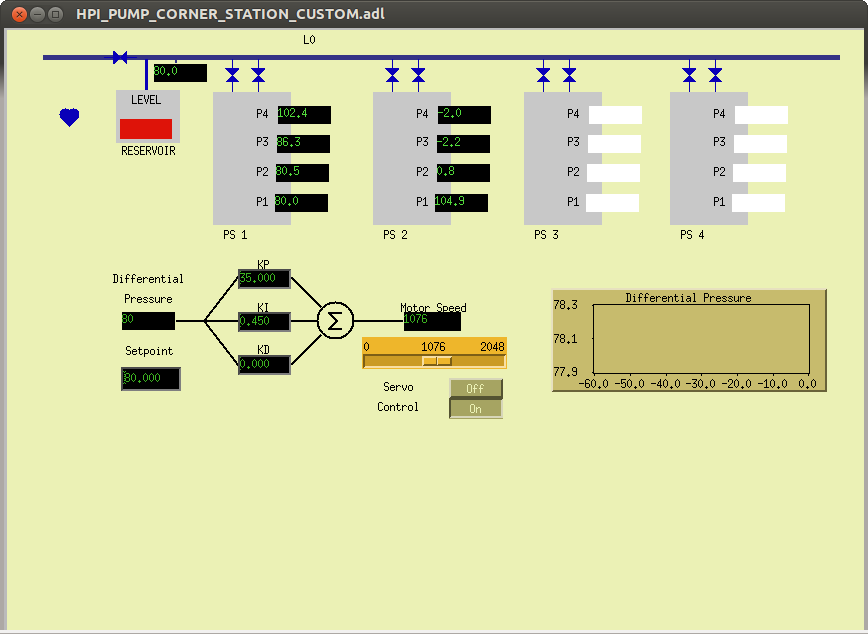
08:25 Hugh to End stations to check on HEPI pumps.
08:47 Fire Dept on site to do annuals on fire extinguishers
09:02 D Barker - out to LVEA to start the Quad tst stand FE
09:59 Quad tst stand back up. Dave and Jim to restart OAF
10:11 Cris to End-X
10:20 Richard out to LVEA by Fil
10:35 OAF is back up
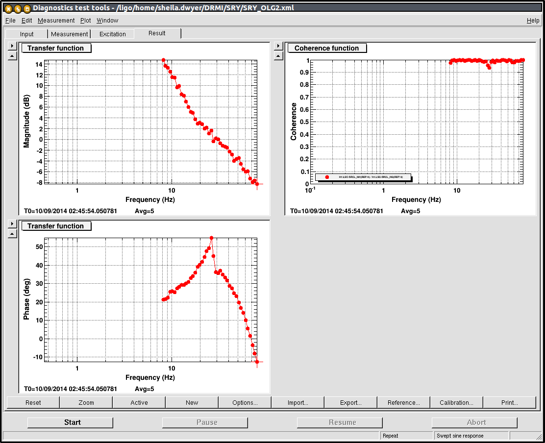
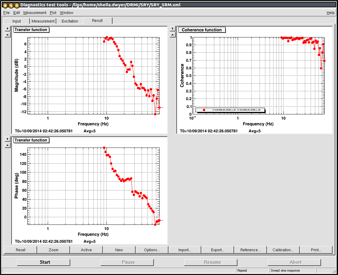
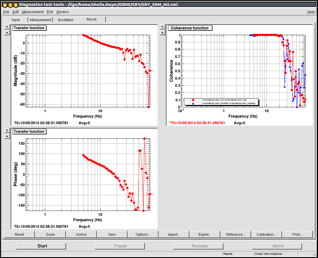
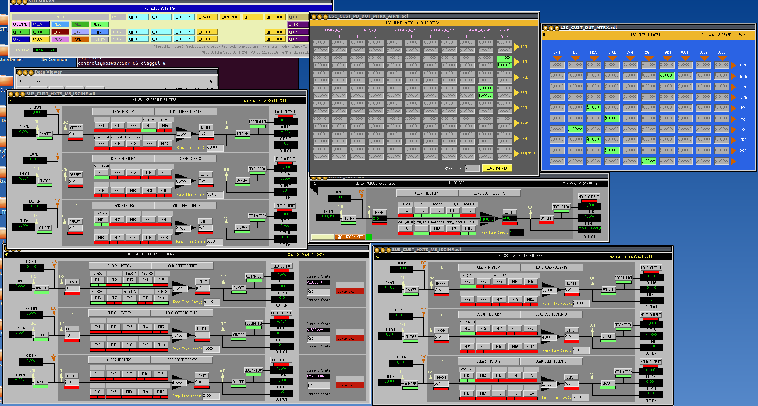
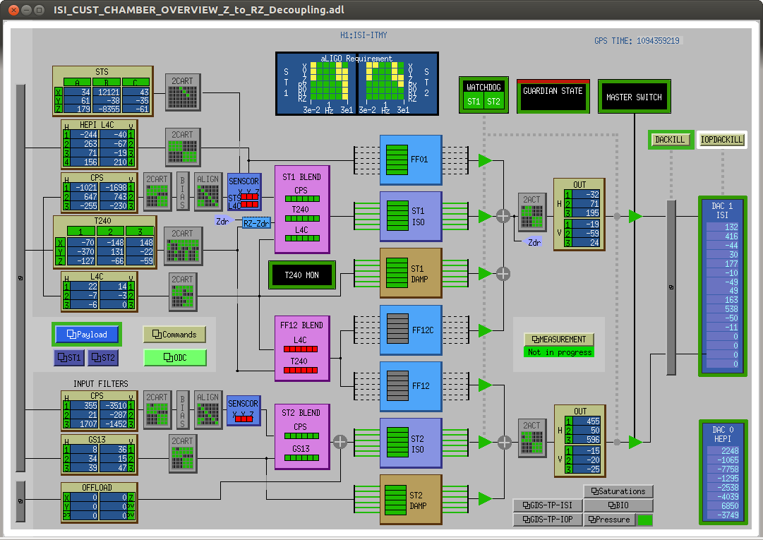
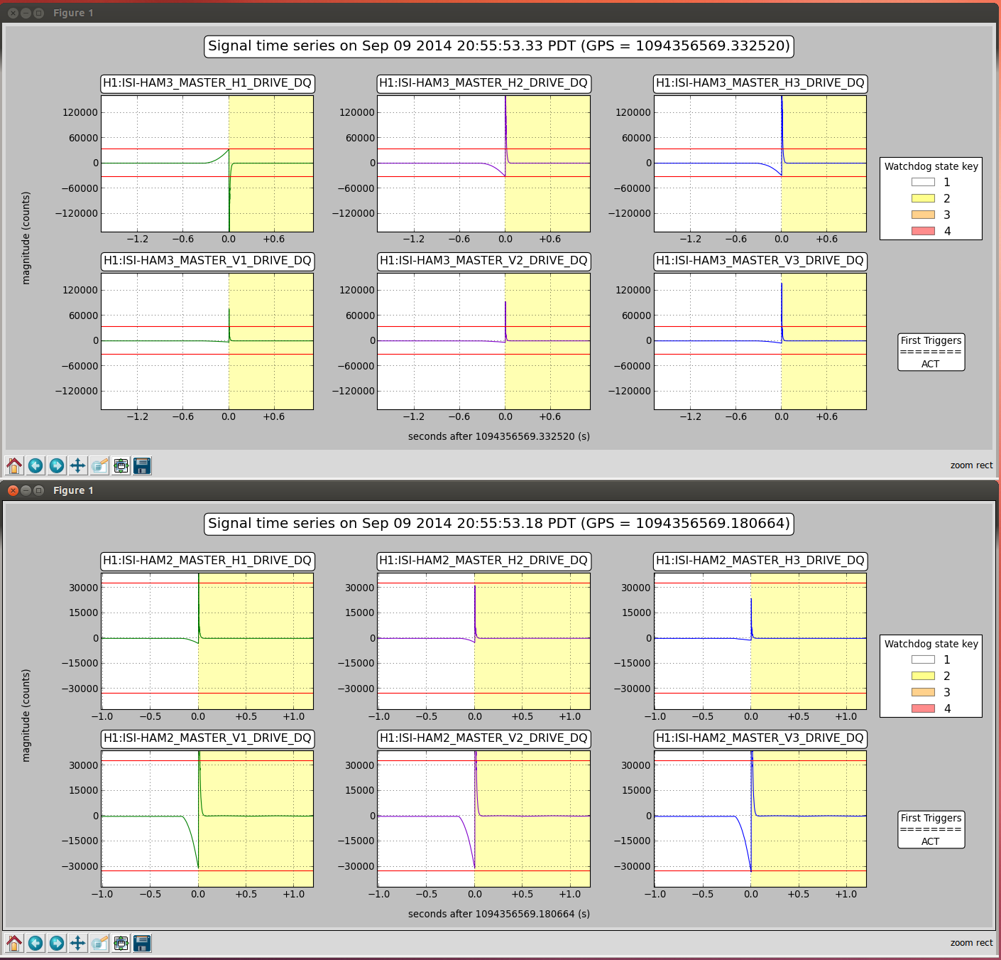
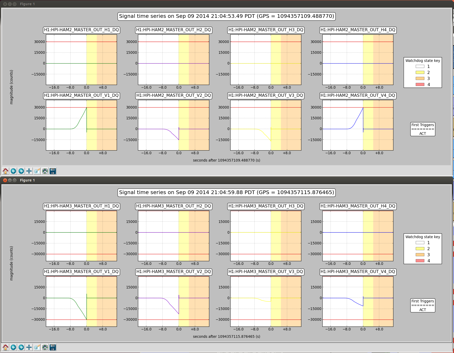
10:47 J Kissell taking down HAM4,5 ISI to recompile model to include OpLev
10:57 Richard out of LVEA
10:58 P King into H1 PSL enclosure to execute work permit
11:02 Hugh back from end stations
11:06 Jason out o LVEA to swap out ITMY oplev LASER
11:07 D Barker - DAQ restart
11:11 Praxxair called 10 minutes ahead of delivery - en route
11:55 Jason out for AHM
12:00 All HANDS MEETING
13:43 Jason back into LVEA -replace bad power supply at IMTY oplev
14:27 Alistair into LVEA to "play with LASERS" - his words.
14:50 Mitch into the LVEA
15:00 Mitch out of the LVEA
15:45 Jason out of LVEA - apparently successful
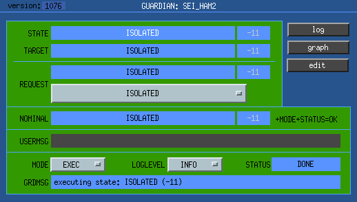 NOMINAL state for HAM managers is "ISOLATED".
 NOMINAL state for BSC managers is "FULLY_ISOLATED" (HPI and both ISIs isolated).
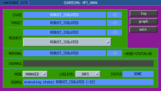 NOMINAL state for HPI is "ROBUST_ISOLATED", for both HAMs and BSCs.
 NOMINAL state for ISI stages is "HIGH_ISOLATED".
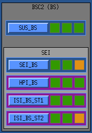
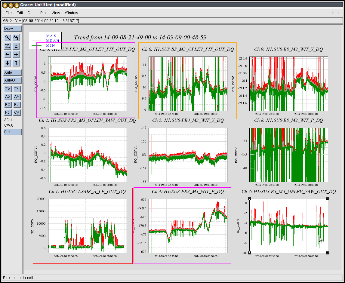


Minute trend of the BS OL over 8.5 hours around this off time. Around 21:30, there is a state change and the pitch DoF becomes much quieter.