8:38 am, David H. to CS VEA, Hartman table work.
8:53 am, Betsy to CS VEA, looking for parts.
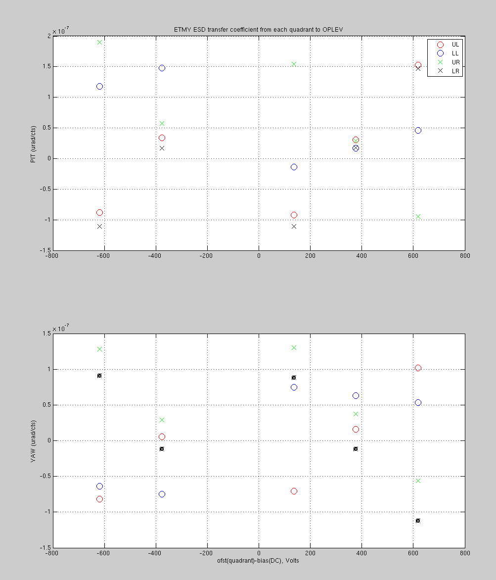
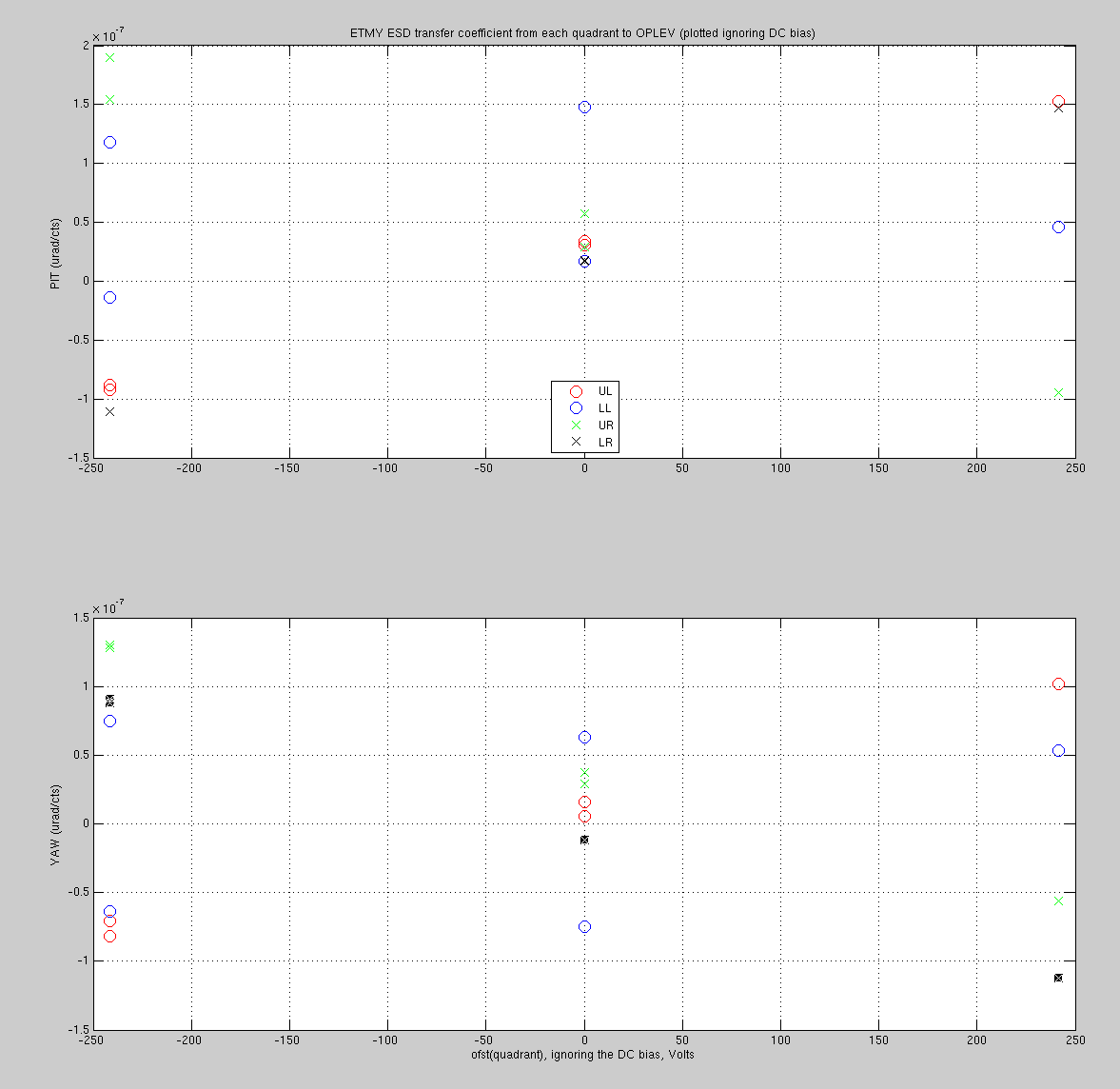
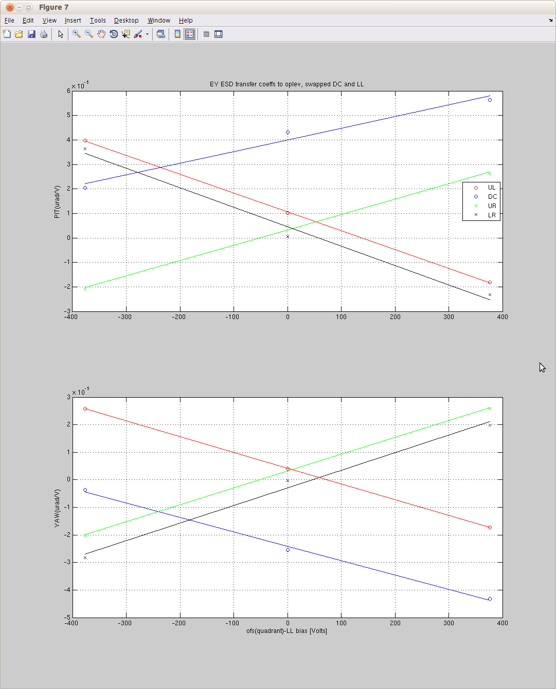
9:00 am, Richard, Rai and Filiberto to Y-End VEA, ESD testing.
9:30 am, Keita and Daniel report a moth problem at X-End Station, no success on trapping the insects.
10:05 am, Cyrus and Adrian to Y-End VEA, upgrade CDS computers.
10:35 am, Bubba and crew CS VEA, remove HAM arm from HAM5 north entrance.
10:45 am, Betsy to CS VEA, West bay area looking for parts.
11:45 am, Cyrus and Adrian to Y-End VEA, install mice on CDS machines.
1:29 pm, Richard, Rai and Filiberto to Y-End VEA, ESD work.
2:47 pm, Received a call from power company, power glitch/outage on grid, reported to Richard M.
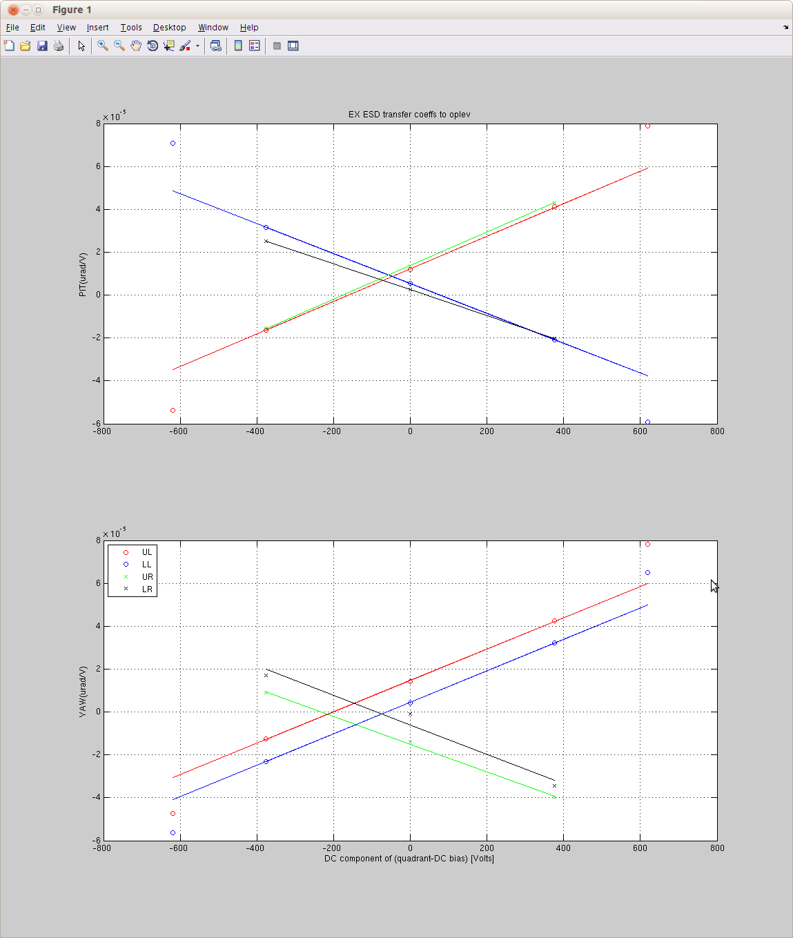
3:10 pm, Filiberto moving ESD test equipment from Y-End station to X-End station.
3:30 pm, Cyrus and Adrian to H1CER, upgrade CDS computer.
4:15 pm, Kiwamu to Y-End VEA, checking laser status, no light.