hugh.radkins@LIGO.ORG - posted 12:28, Saturday 25 January 2014 (9556)
Mucked around in Blend Filter Space on ITMx ~0930 -- 1200pst
Tried a few things such as 250mHz blends on Stage1 & 2 for all dofs, w & w/o notches, tried notch on T240 (not helpful.)
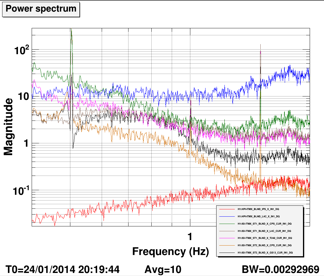
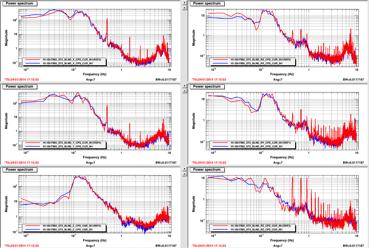
Noise of Stage2 CPSX & GS13X blend In1 was higher generally between .5 & 1 hz with the 250 vs 750 blend, that seemed strange.
.5hz peak appears on St1 CPSX when switched to T100.44Notch on Stg1X from 750mHz, that too seemed strange to me.
Left ITMx in same configuration I found it this morning: 750mHz blends everywhere except St1 Y has T100mHz_NO.44 and Stage2 X & Y has Narrow_Notch added.
No alignment changes.