kyle.ryan@LIGO.ORG - posted 12:11, Wednesday 05 December 2012 (4843)
IP9 pump #1 (pumpA) taken offline briefly
Was considering changing from STEP to FIXED (5000V) voltage but didn't
Was considering changing from STEP to FIXED (5000V) voltage but didn't
WP 3589
I modified the IOP model for the BSC1 SEI system (h1seib1) to permit up to 10 IPC receive errors per second from the h1iopsusb123 sender (SUS ITMY). We are currently experiencing about 5 errors per day on this Dolphin link, we currently dont know what the problem is. We hope the upgrade to RCG2.6 will resolve this issue.
I did a cursory test of the IPC watchdog by PANICing the SUSB123 DACKILL and verifying that the SEIB1 tripped. It is not possible to test that an error rate of >10 will trip SEIB1 without rebooting the SUSB123 and possibly disrupting the mode cleaner work.
This entry is for activity that occurred on Tuesday, 04 Dec 2012.
Viewports, etc. removed from chamber. Condition of chamber documented. Support tubes wrapped and bellows protection installed. Brushing of collar complete by the end of the day.
[Rodica, Luke, David, Cheryl, Giacomo]
Many activities were carreid out in parallel today (or, I should say, yesterday). Mainly (and besides what has already been reported in other posts):
- MC REFL telescopes were assembled, positioned on the table and the beam aligned up to the last mirror (MC REFL 2 Bottom). A temporary baffle blocks it just out of the periscope.
- IO QPD 1 was installed on the table extension, together with the beam dump that catches its reflection
- With help from Keita and Corey, two actuated siskiyou mounts have been fixed (there was a problem with the ball bearing), and stop-collars installed. Stop collars on the actuated mount after the IO Periscope have not been installed to avoid comprimising the alignment of the input beam. Needs to be done before pump-down.
- PRM surrogate was placed on the table; position needs to be refined.
- the HWP is ready and installed in the mount, although temporarily on a different post to be used in the FI to align the forward rejected beam.
Some parts for the viewport simulator were missing; they were procured in the afternoon and sent to C&B. Should be out tomorrow.
Attached are plots of dust counts > .3 microns and > .5 microns in particles per cubic foot from approximately 6 PM Dec. 3 to 6 PM Dec. 4. Also attached are plots of the modes to show when they were running/acquiring data.
The h1broadcast0 computer memory has been changed to 24G.

The daqd process would not run, found that the process appears to have been built against framecpp-1.19.24 while other daqd processes are built against framecpp-1.18.2.  Earlier the framecpp link in /opt/rtapps was changed to support compiling a new version of daqd on the data concentrator (which failed), and ended up pointing to framecpp-1.18.2, which caused the h1broadcast0 daqd to try to use the wrong library.  I fixed this by changing the ld.so.conf.d/framecpp.conf file to point to framecpp-1.19.24 on h1broadcast0 and doing a re-cache. It seems to be running now.

Cloned h1dmt0 to create h1dmt1 (to be done tomorrow).  h1dmt0 is back running.
Jim, Hugo,
IO signed off on HAM3 this afternoon. We went in and balanced the ISI. The payload is not supposed to change anymore. We recorded the CPS readouts for both locked and unlocked configurations:
| Locked (Counts) |
Unlocked |
Shift (Counts) |
|
| H1 | -380 | 87.98 | 467.98 |
| H2 | 170 | 504.36 | 334.36 |
| H3 | -60 | 139.12 | 199.12 |
| V1 | 120 | 145.64 | 25.64 |
| V2 | -350 | -518.82 | 168.82 |
| V3 | 250 | 108.37 | 141.63 |
Requirements are (E1000309-v12):
shift<1600cts
Readouts<2000cts
The locked/unlocked shifts are way within requirements. We are looking forward to hearing back from IO on how unlocking affected them, if it did.
All electronics are powered back up. covers are held up with clippers and testing signs are on. The first measurements for the final in-chamber testing of HAM3-ISI will start tonight.
Note: The HAM-ISI master model was updated by LLO today. We are still running the previous version. I will soon transfer the update here.
Giacomo, Hugo,
We checked that the cavity was still flashing with the ISI unlocked. It is.
We then tried turning on the damping and the controllers level 2. The cavity was still flashing.
Dave and Jim
We worked on the problem of the SUS ITMY model frequently running over its 60uS time limit. This has become a critical problem in that the user model is causing the IOP to send IPC errors to the SEI BSC1 system, which trips the DACKILL there and destroys Vincent's measurements. First we replaced the h1susb123 computer with the not-being-used-at-the-moment h1seib3 front end computer. This involved a DHCP change on h1boot and moving the one-stop pci bus extended fiber. This did not fix the problem so we reverted back to the original h1susb123 computer.
Jim went to EY and looked at the BIOS of a front ends there. He compared that with the BIOS setting of h1susb123 and discovered that the EY configuration had many more settings disabled compared with the MSR. He then applied the EY configuration to h1susb123 and we found that the SUS ITMY model running long problem was fixed. He then applied this BIOS setting to following computers
h1sush2a, h1sush2b, h1sush34, h1seib1, h1seih23, h1oaf0, h1lsc0
After this h1lsc0 would not boot, we will get back to this later. Strangely the IOP models on h1sush2a and h1sush34 now ran over their CPU limit and the CPU usage was much more noisy than before, but only these two models! So we put back the original "MSR BIOS configuration" onto these two front ends only, and the models on these computers are running correctly again. We need to figure out why identical BIOS settings cause failure to boot and models running long problems.
In the process of changing the BIOS on h1susb123 we accidentally Dolphin crashed all MSR front ends, so that made for an excellent opportunity to change the BIOS on all systems. We burt restored SUS MC1,2,3 to 10am this morning to restore the DC offsets correctly.
Dan (LDAS) upgraded h1dmtqfs0 to Solaris 11.0. This is the QFS writer for the /gdsh1 DMT file system. He is also upgrading h2ldasgw1 on H2 DAQ.
After Mark had calculated and loaded the offsets and gains, I entered the cleanroom and set the M1 stage BOSEMs to 50% OLV. We should be ready to run a set of TFs to check it's post-move health in preparation for glass install early next week. We'll continue to investigate the M3 UL issue thereafter. Status: suspended, covered, and ready for M1 level TFs.
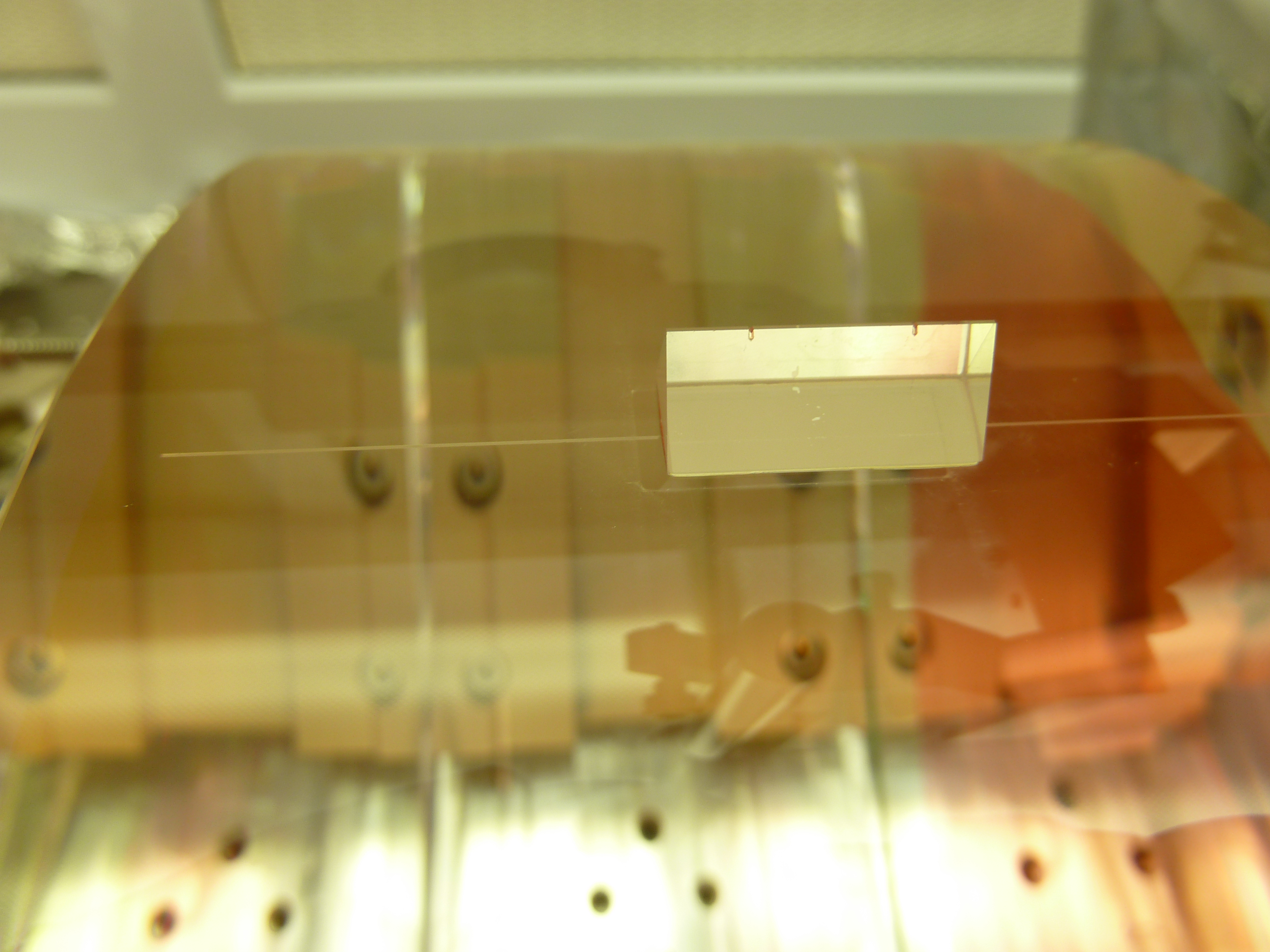
Yesterday I spent the day rebuilding the HXTS prism gluing measurement apparatus in order to accomodate the HLTS sized optic. At the end of the day I finally glued the prism on. Today, Gerardo removed the fixturing and sees that the prism is 2mm out of spec in the pitch-direction. Ugh. The d-value direction (or distance up from the scribe line) has been corrected. Both of these dimension differences from the first round of gluing can be seen in the attached picture where the phantom footprint from the last glued on prism was. The new prism should line up with the phantom line on the left end of the prism, but should remain at the current horizontal position on the line. I estimate that this error would induce roughly ~40mRad of pitch error. Because this glue bond is still somewhat fresh (only an overnight room temp cure) and the position error is so large, Gerardo is placing the prism down into an acetone bath for the night to remove it.
Mulligan-again for tomorrow.
It is unfortunate that you cannot check any of the setup measurements once the prism is in the fixture and glued down. We *think* this happened because the measurement apparatus is not very good at staying alignment when traveling up and down (away from the optic) in order to adjust for focus. You focus on the scribe line on the optic during setup and then you must slide up to focus on the notches on the prism which are many mm of focus different. Likely this focal plane change has some sideshift (on the order of the 2mm error we now see). I'm not sure what a good fix for this is this. I'll try removing some of the brackets between the traveling bore-scope and the horizontally mounted height guage.
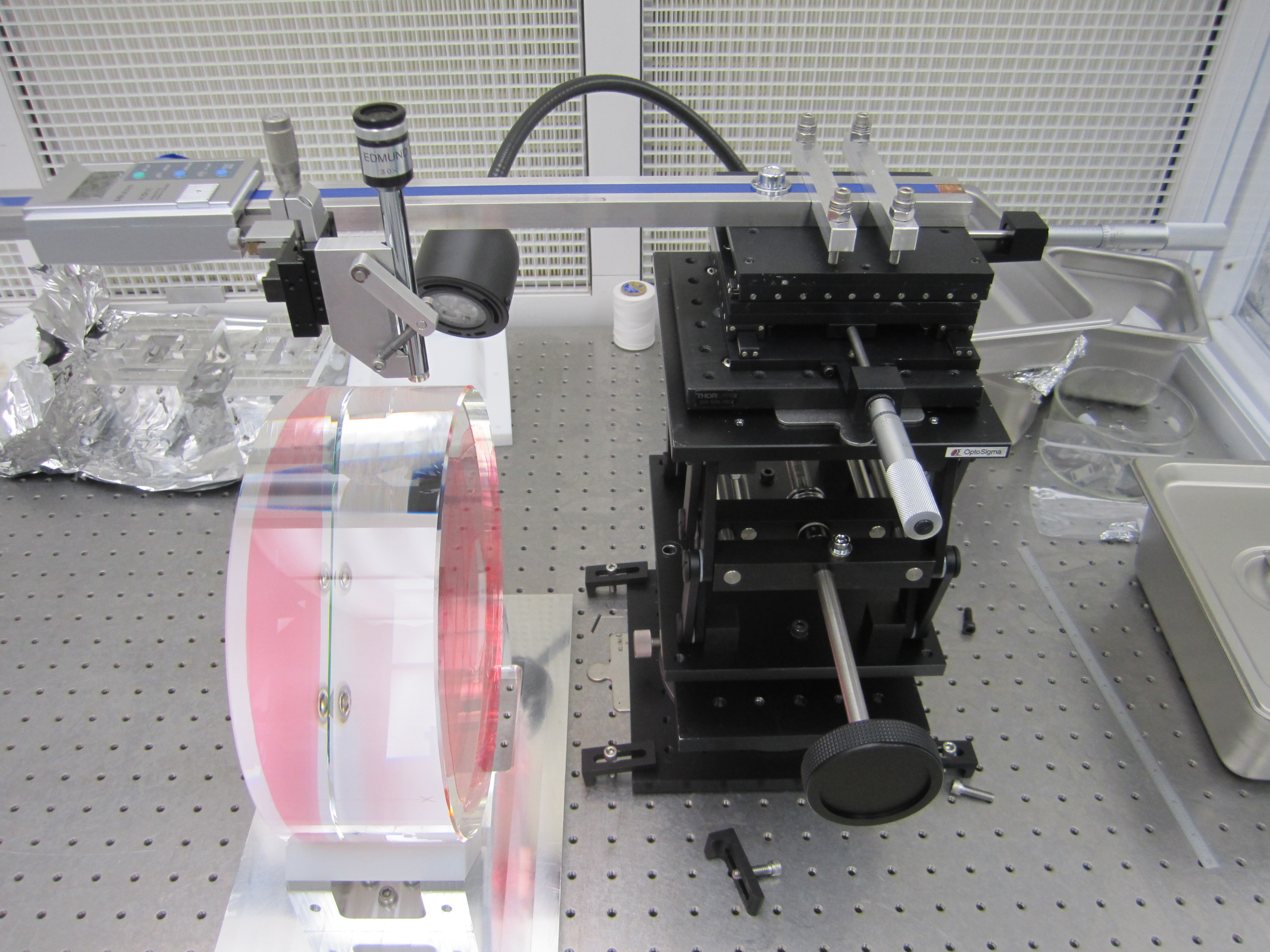
Playing with the measurement apparatus today, Gerardo and I discovered that the bore scope 1) wobbles up and down relative to g, and 2) runs downhill by ~3mm over a 300mm length due to the weight if itself hanging off the end of the horizontally mounted height guage (see pic attached). Both piggy-backed jacks have slop in this direction. I can remedy 2) via shimming the entire stack of joints, but I'm not likely to be able to improve 1) without rearranging the entire measurement motivation. Hopefully 2) was the larger contributor to Monday's error. The top portion of the apparatus is the same as what I used to glue prisms to MC2 and PR2, so we would have see some slop then as well, however since the optics were smaller, the travel (and subsequent shifting of load) must have been less noticeable.
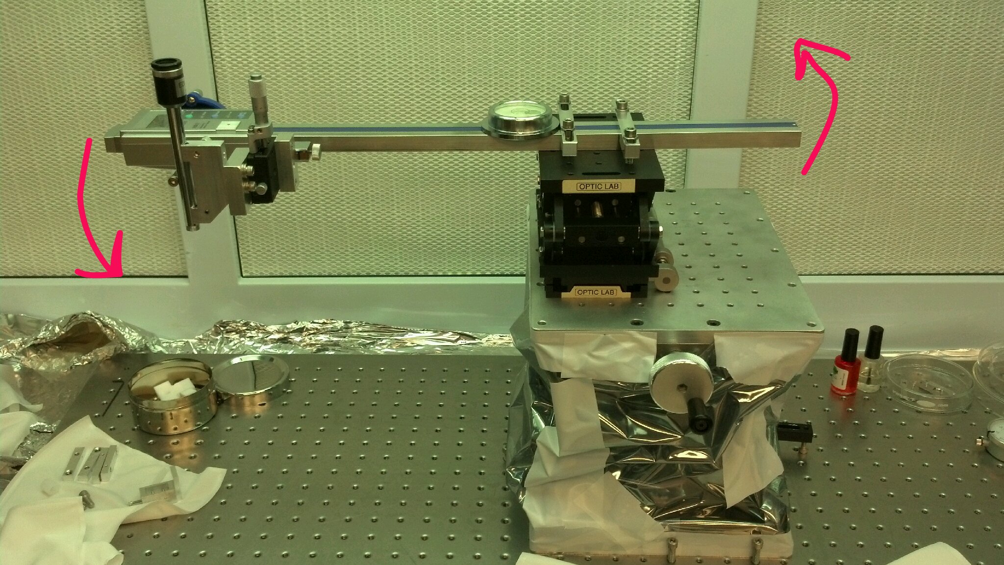
Attached is the LLO gluing apparatus, shown with an HLTS optic. It also is stacked lab jacks.
[Mark B, Stuart A]

Ref: WP#3588

PR2 is being used overnight, testing the functionality of automated testing scripts (TF's and Power Spectra), following the recent SUS infrastructure and CDS updates.

The measurement status indicator will be ON, however, the Master Switch will remain OFF for the duration of the tests (i.e. no excitations will get though to the optic).

I will update the log when the measurements are complete and damping loops are re-established.
Measurements on PR2 are complete. Master Switch remained OFF throughout the night.

Master Switch engaged and Damping loops restored at 9:30am (CT), 7:30am (PT).
The alignment of the MC was checked with the IR beam from the PSL. The beam was well aligned through the 3 MC irises, and the MC was flashing. DavidT and I removed the iris in front of MC2, and installed it between MC3 and IM1. This allows IO to monitor MC alignment, and continue HAM2 alignment, all from HAM2, meaning that we have exited HAM3. However, we have about 30 minutes right now to check the alignment of the beam dumps behind MC2 with the IR beam something we were unable to do earlier today.
And now we are, as of 3:30 this afternoon. Hugo and Jim unlocked, rebalanced, and the table is floating.
Mark B.

I took OL readings on PR3 (and calculated appropriate gains and offsets) after Travis installed OSEMs on PR3 and left them backed out.

M1T1  26124.3  1.1483561  13062.15
M1T2    30353 0.98837018   15176.5
M1T3  28842.1  1.0401462  14421.05
M1LF  25990.7   1.154259  12995.35
M1RT  26134.2  1.1479211   13067.1
M1SD  28493.2  1.0528828   14246.6
M2UL  18073.3  1.6599072   9036.65
M2LL  20597.1  1.4565157  10298.55
M2UR  19602.2  1.5304405    9801.1
M2LR  17998.4  1.6668148    8999.2
M3UL -3.19153 -9399.8803 -1.595765
M3LL  23289.9   1.288112  11644.95
M3UR  24780.1  1.2106489  12390.05
M3LR    17455  1.7187052    8727.5

There's something wrong with M3UL (not fully backed out?), but I'll enter the remaining gains and offsets to the OSEMINF screen.
Mark B.

I entered the above gains and offsets except that I used 1.000 and -15000 for M3UL. I then created a new h1suspr3_safe.snap file. I archived the old as h1suspr3_safe20121005.snap based on its modification date, and made a spare copy of today's new one as h1suspr3_safe20121204.snap.
Mark B., Travis

Travis replugged the cable and M3UL came good. Its OL was

M3UL 17553.2 1.7091  8776.6

I entered the gain and offset and redid the safe.snap file (spare copy as h1suspr3_safe20121205.snap).

We had a single IPC error this afternoon and the SEIB1 IOP ran through it without DACKILL'ing the ISI. So far, so good.