SEI seismometer mass check - Monthly - Closes FAMIS 26492
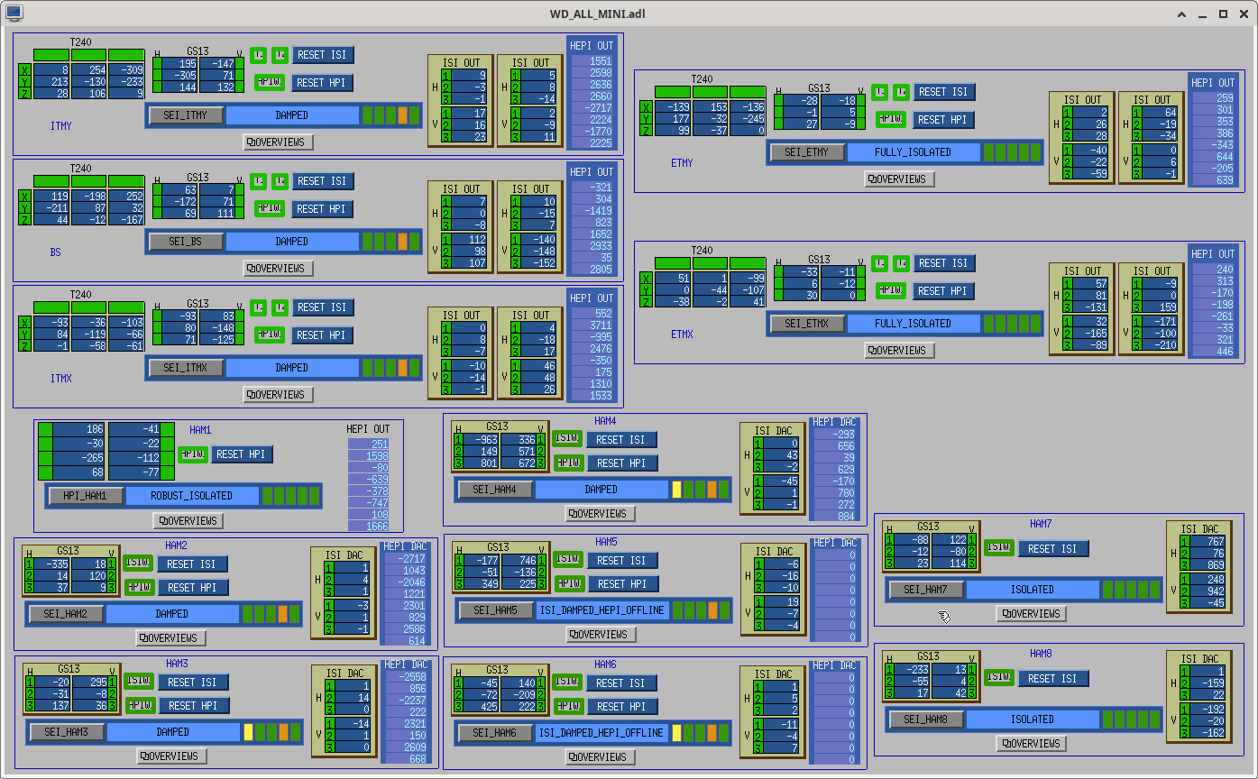
I've also attached the WD_ALL Mini Screen of what states the SEI platforms were in (FAMIS calls for DAMPED or ISOLATED but since we're venting, some of these are in different variants of damped or isolated.
T240
Averaging Mass Centering channels for 10 [sec] ...
2024-08-02 13:21:31.272178
There are 27 T240 proof masses out of range ( > 0.3 [V] )!
ETMX T240 2 DOF X/U = -0.632 [V]
ETMX T240 2 DOF Y/V = -0.461 [V]
ETMX T240 2 DOF Z/W = -0.522 [V]
ITMX T240 1 DOF X/U = -1.764 [V]
ITMX T240 1 DOF Y/V = -0.302 [V]
ITMX T240 2 DOF X/U = -0.476 [V]
ITMX T240 2 DOF Y/V = -0.35 [V]
ITMX T240 2 DOF Z/W = -0.469 [V]
ITMX T240 3 DOF X/U = -1.844 [V]
ITMX T240 3 DOF Y/V = -0.387 [V]
ITMY T240 1 DOF Y/V = -0.472 [V]
ITMY T240 1 DOF Z/W = -0.611 [V]
ITMY T240 2 DOF Z/W = -0.629 [V]
ITMY T240 3 DOF X/U = -1.345 [V]
ITMY T240 3 DOF Y/V = -0.349 [V]
ITMY T240 3 DOF Z/W = -1.75 [V]
BS T240 1 DOF X/U = -0.594 [V]
BS T240 1 DOF Y/V = -0.928 [V]
BS T240 1 DOF Z/W = -0.457 [V]
BS T240 2 DOF X/U = -0.542 [V]
BS T240 2 DOF Y/V = -0.424 [V]
BS T240 2 DOF Z/W = -0.626 [V]
BS T240 3 DOF X/U = -0.712 [V]
BS T240 3 DOF Y/V = -0.676 [V]
BS T240 3 DOF Z/W = -1.191 [V]
HAM8 1 DOF Y/V = -0.505 [V]
HAM8 1 DOF Z/W = -0.812 [V]
All other proof masses are within range ( < 0.3 [V] ):
ETMX T240 1 DOF X/U = -0.133 [V]
ETMX T240 1 DOF Y/V = -0.112 [V]
ETMX T240 1 DOF Z/W = -0.159 [V]
ETMX T240 3 DOF X/U = -0.1 [V]
ETMX T240 3 DOF Y/V = -0.226 [V]
ETMX T240 3 DOF Z/W = -0.103 [V]
ETMY T240 1 DOF X/U = 0.022 [V]
ETMY T240 1 DOF Y/V = 0.09 [V]
ETMY T240 1 DOF Z/W = 0.148 [V]
ETMY T240 2 DOF X/U = -0.098 [V]
ETMY T240 2 DOF Y/V = 0.152 [V]
ETMY T240 2 DOF Z/W = 0.049 [V]
ETMY T240 3 DOF X/U = 0.155 [V]
ETMY T240 3 DOF Y/V = 0.041 [V]
ETMY T240 3 DOF Z/W = 0.089 [V]
ITMX T240 1 DOF Z/W = -0.092 [V]
ITMX T240 3 DOF Z/W = -0.289 [V]
ITMY T240 1 DOF X/U = -0.25 [V]
ITMY T240 2 DOF X/U = -0.08 [V]
ITMY T240 2 DOF Y/V = -0.185 [V]
HAM8 1 DOF X/U = -0.287 [V]
Assessment complete.
STS
Averaging Mass Centering channels for 10 [sec] ...
2024-08-02 13:24:48.269297
There are 2 STS proof masses out of range ( > 2.0 [V] )!
STS EY DOF X/U = -3.98 [V]
STS EY DOF Z/W = 2.725 [V]
All other proof masses are within range ( < 2.0 [V] ):
STS A DOF X/U = -0.679 [V]
STS A DOF Y/V = -0.648 [V]
STS A DOF Z/W = -0.561 [V]
STS B DOF X/U = 0.287 [V]
STS B DOF Y/V = 0.996 [V]
STS B DOF Z/W = -0.446 [V]
STS C DOF X/U = -0.848 [V]
STS C DOF Y/V = 0.865 [V]
STS C DOF Z/W = 0.506 [V]
STS EX DOF X/U = -0.136 [V]
STS EX DOF Y/V = -0.016 [V]
STS EX DOF Z/W = 0.076 [V]
STS EY DOF Y/V = 0.037 [V]
STS FC DOF X/U = 0.24 [V]
STS FC DOF Y/V = -1.064 [V]
STS FC DOF Z/W = 0.627 [V]
Assessment complete.
