erik.vonreis@LIGO.ORG - posted 05:46, Tuesday 17 March 2026 (89531)
Workstations updated
Workstations updated and rebooted. This was an os packages update. Conda packages were not updated.
Workstations updated and rebooted. This was an os packages update. Conda packages were not updated.
TITLE: 03/17 Eve Shift: 2330-0500 UTC (1630-2200 PST), all times posted in UTC
STATE of H1: Planned Engineering
INCOMING OPERATOR: None
SHIFT SUMMARY: I'm not convinced that the +90 phasing was correct for AS_B_RF45, the non-stellar alignment is making it tough to tell. PRMI locked fairly easily althought I can't seem to fix the Pitch misalignment, DRMI isn't so kind. It struggles to lock for more than ~7 seconds at the end of the shift.
LOG:
| Start Time | System | Name | Location | Lazer_Haz | Task | Time End |
|---|---|---|---|---|---|---|
| 23:40 | TCS | Sophie | Cheta | yes | Cheta work | 00:51 |
TITLE: 03/17 Eve Shift: 2330-0500 UTC (1630-2200 PST), all times posted in UTC
STATE of H1: Planned Engineering
OUTGOING OPERATOR: Tony
CURRENT ENVIRONMENT:
SEI_ENV state: CALM
Wind: 17mph Gusts, 14mph 3min avg
Primary useism: 0.04 μm/s
Secondary useism: 0.25 μm/s
QUICK SUMMARY:
TITLE: 03/17 Day Shift: 1430-2330 UTC (0730-1630 PST), all times posted in UTC
STATE of H1: Planned Engineering
INCOMING OPERATOR: Ryan C
SHIFT SUMMARY:
17:13 UTC GRB -Short E630194 H1 was in Idle.
ITMX was moved to get better X arm light earlier today. Since then we have been able to Lock PRMI.
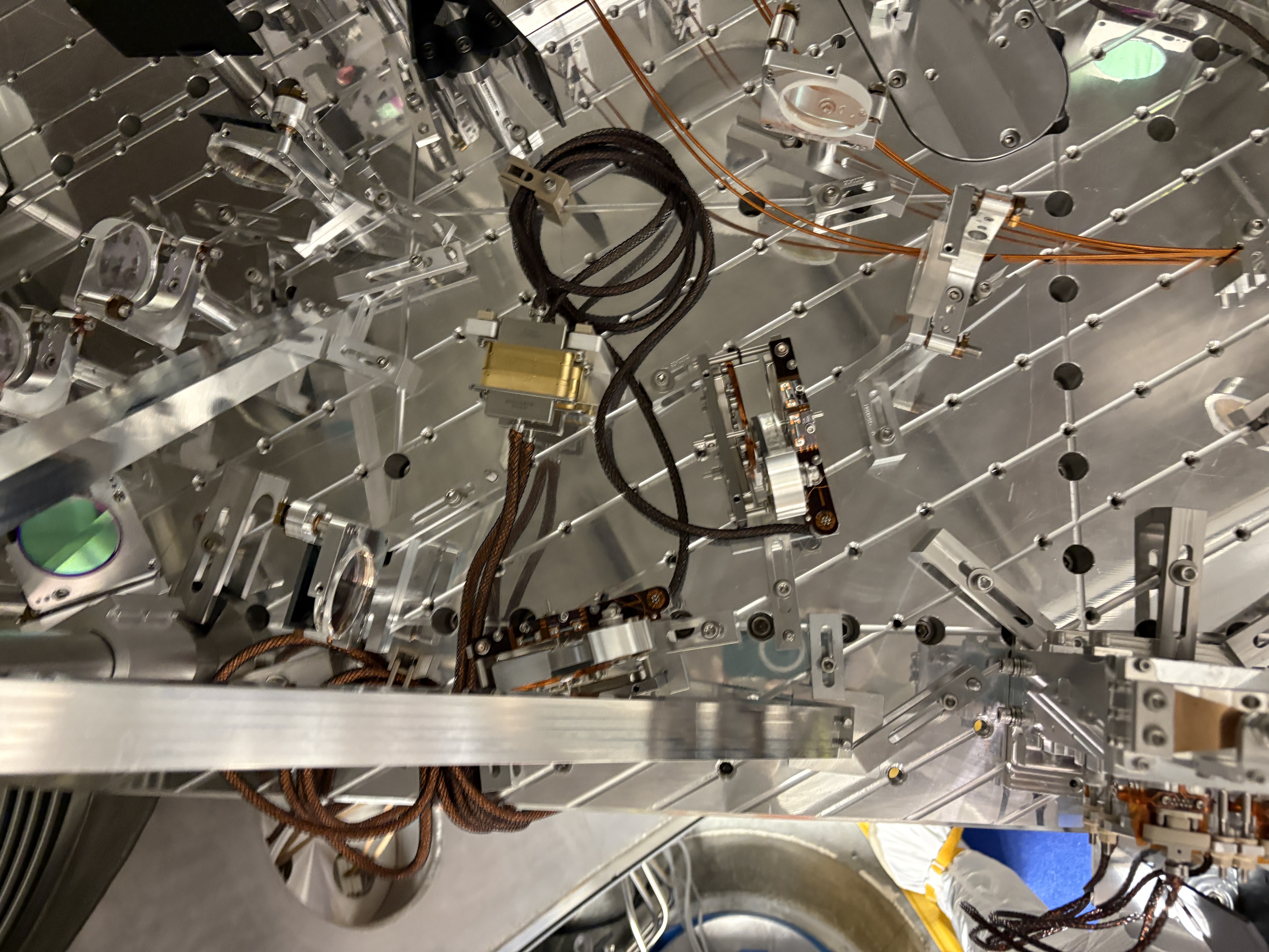
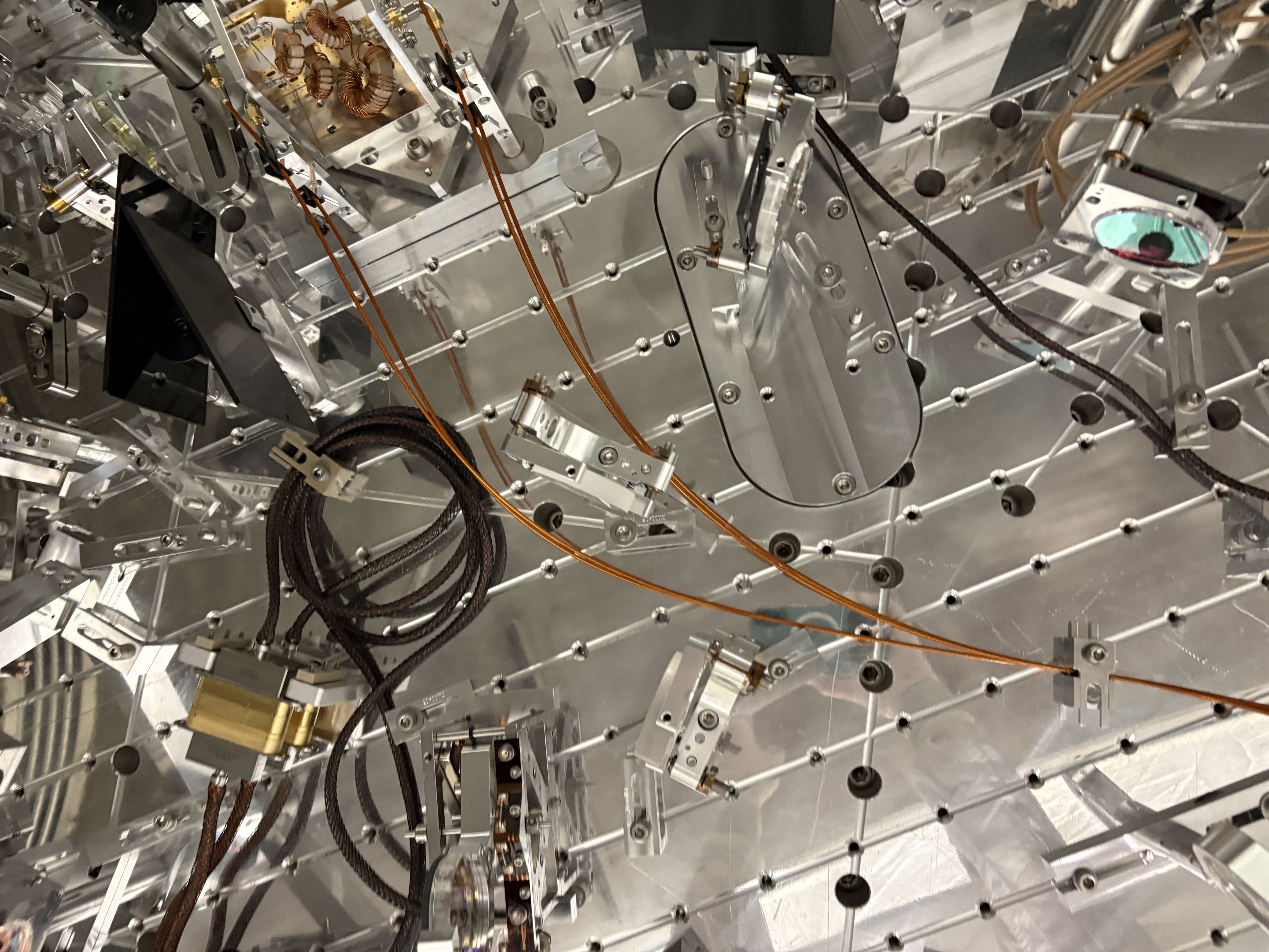
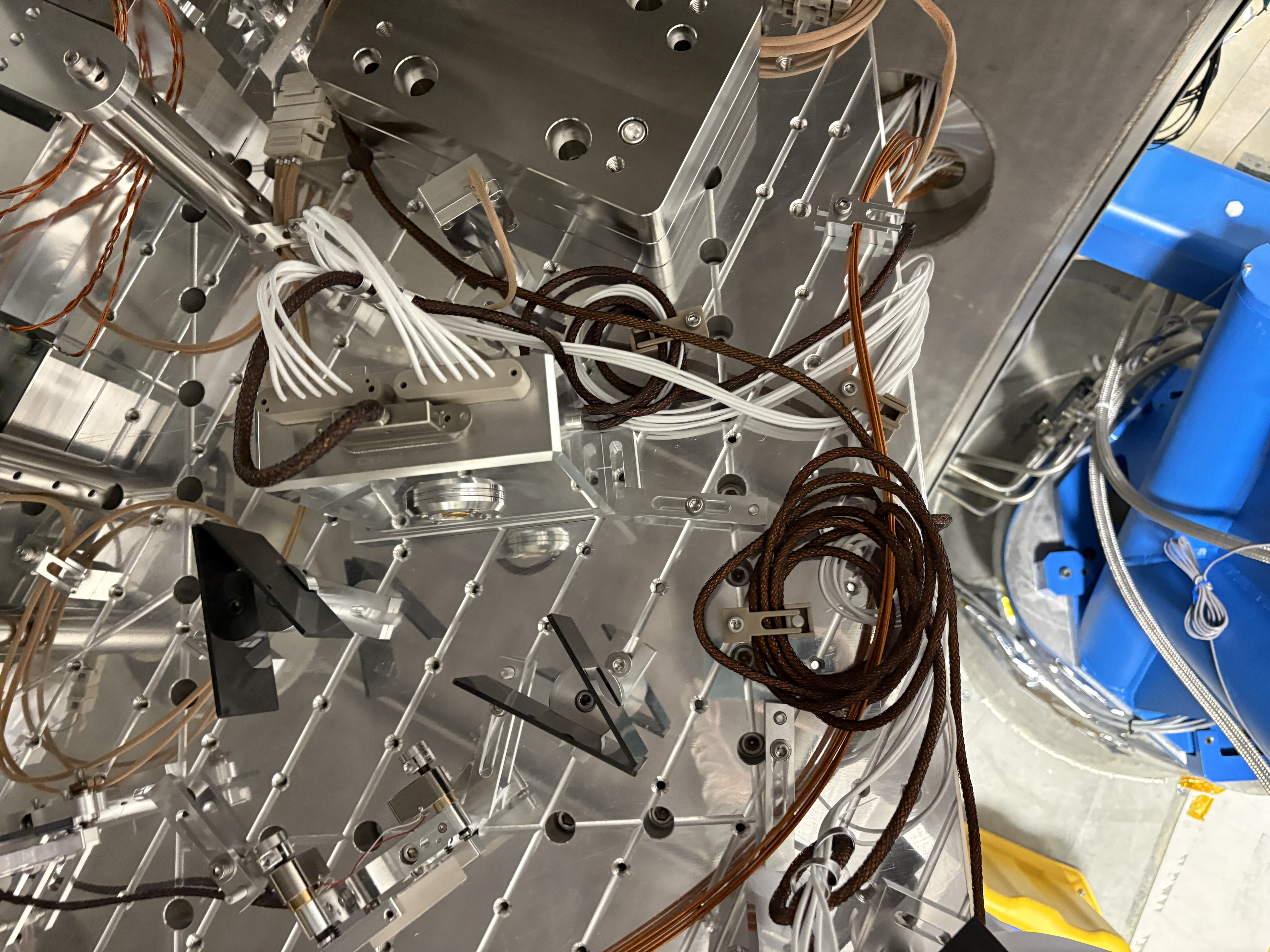
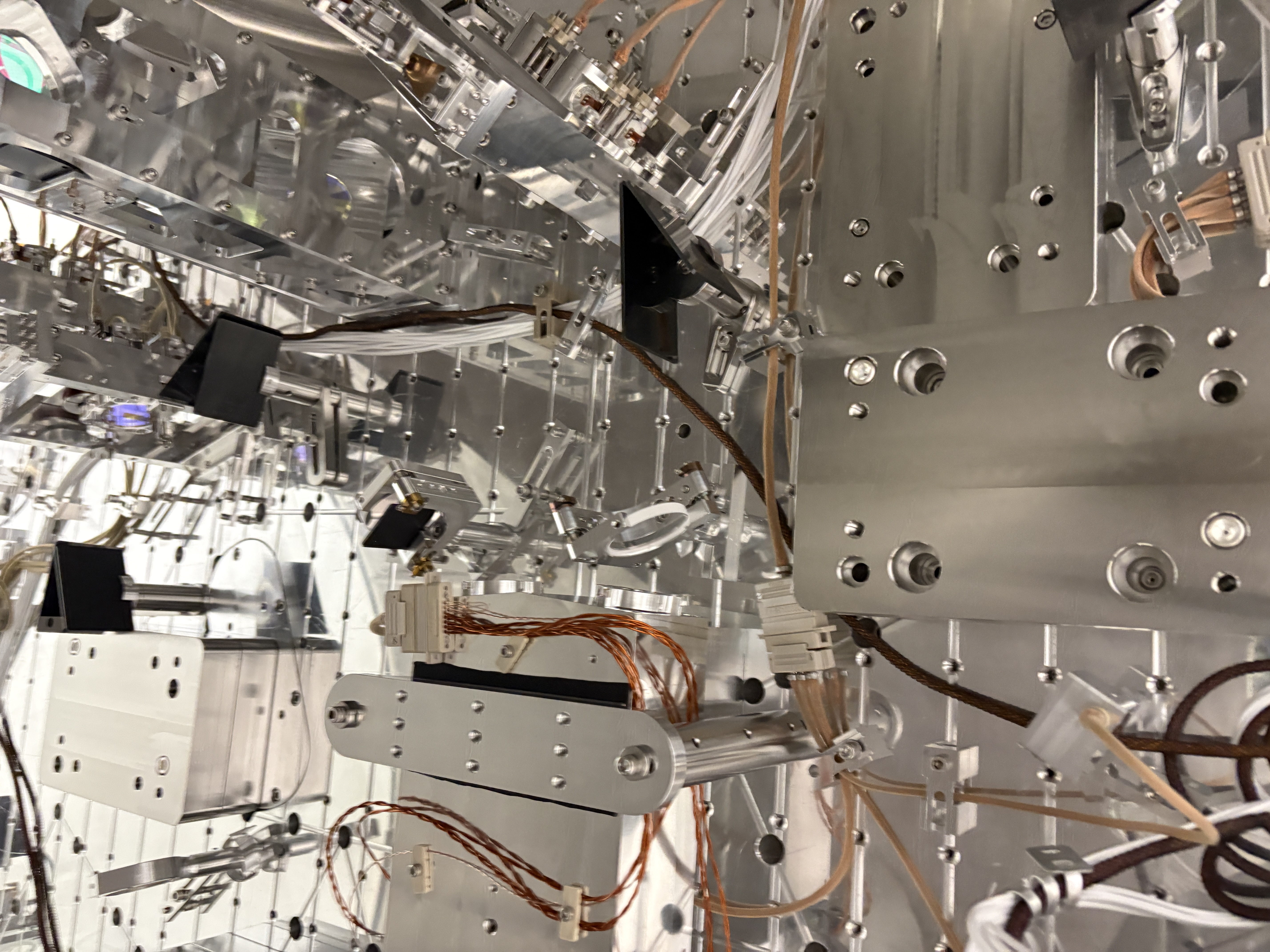
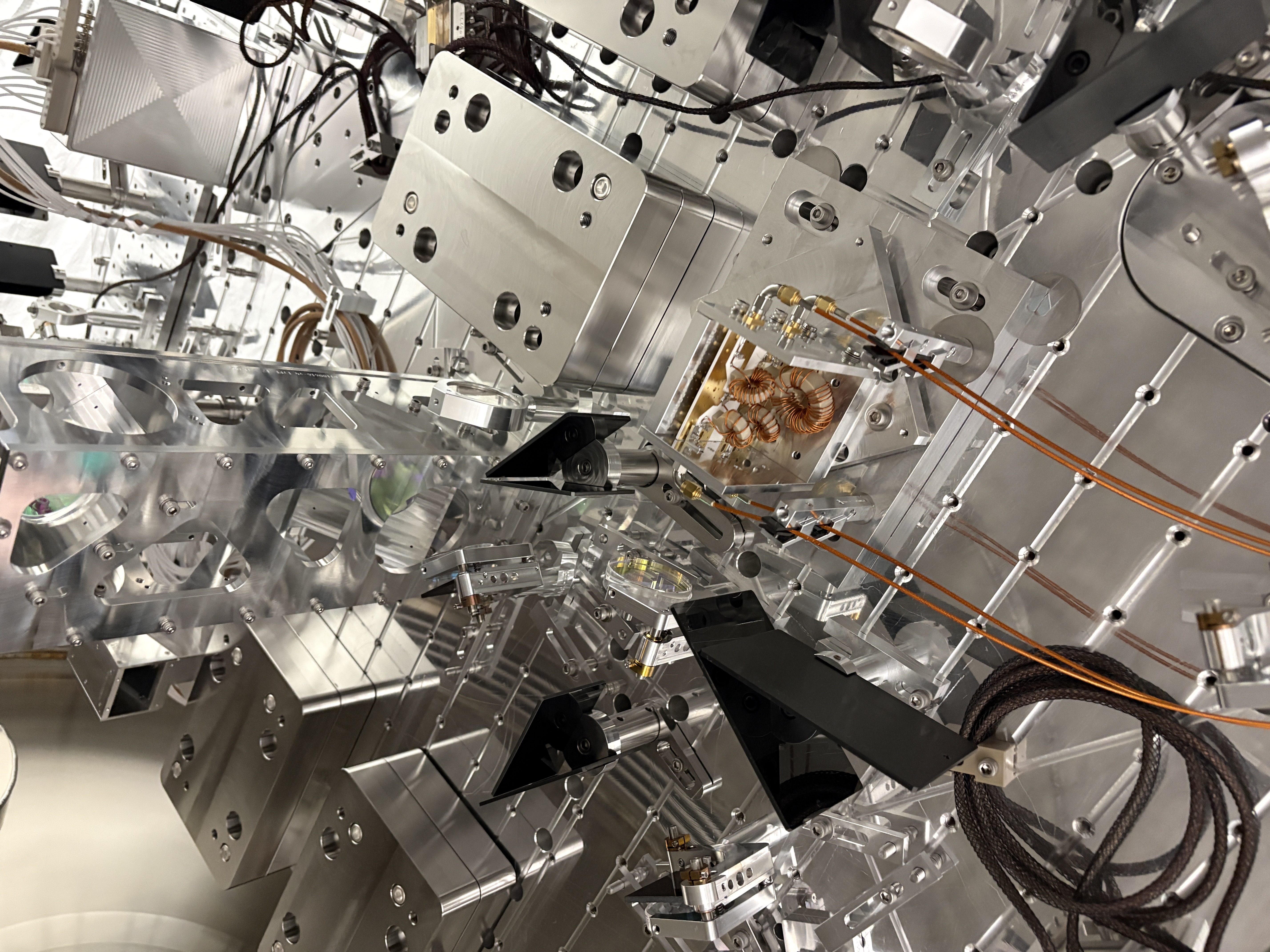
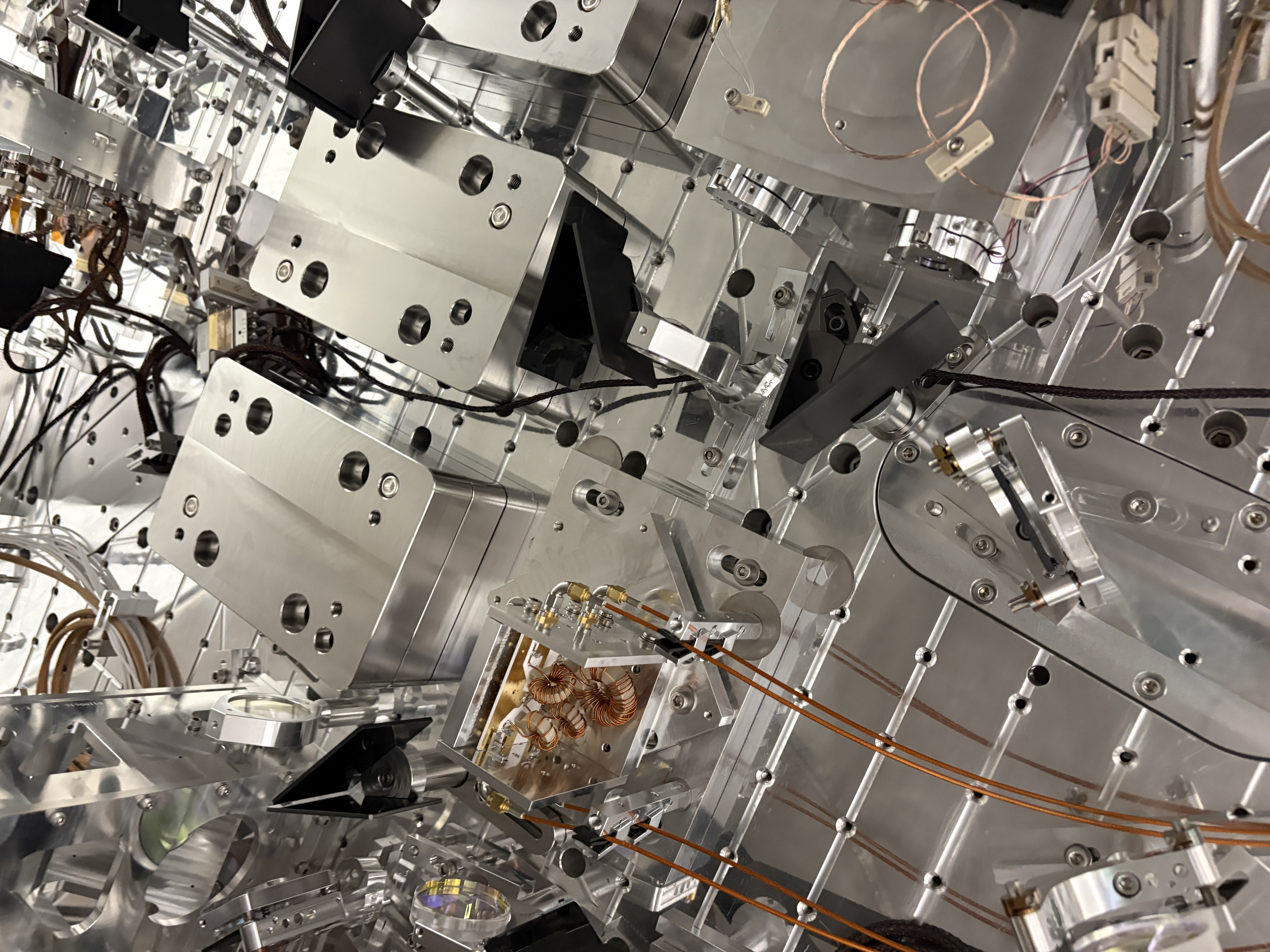
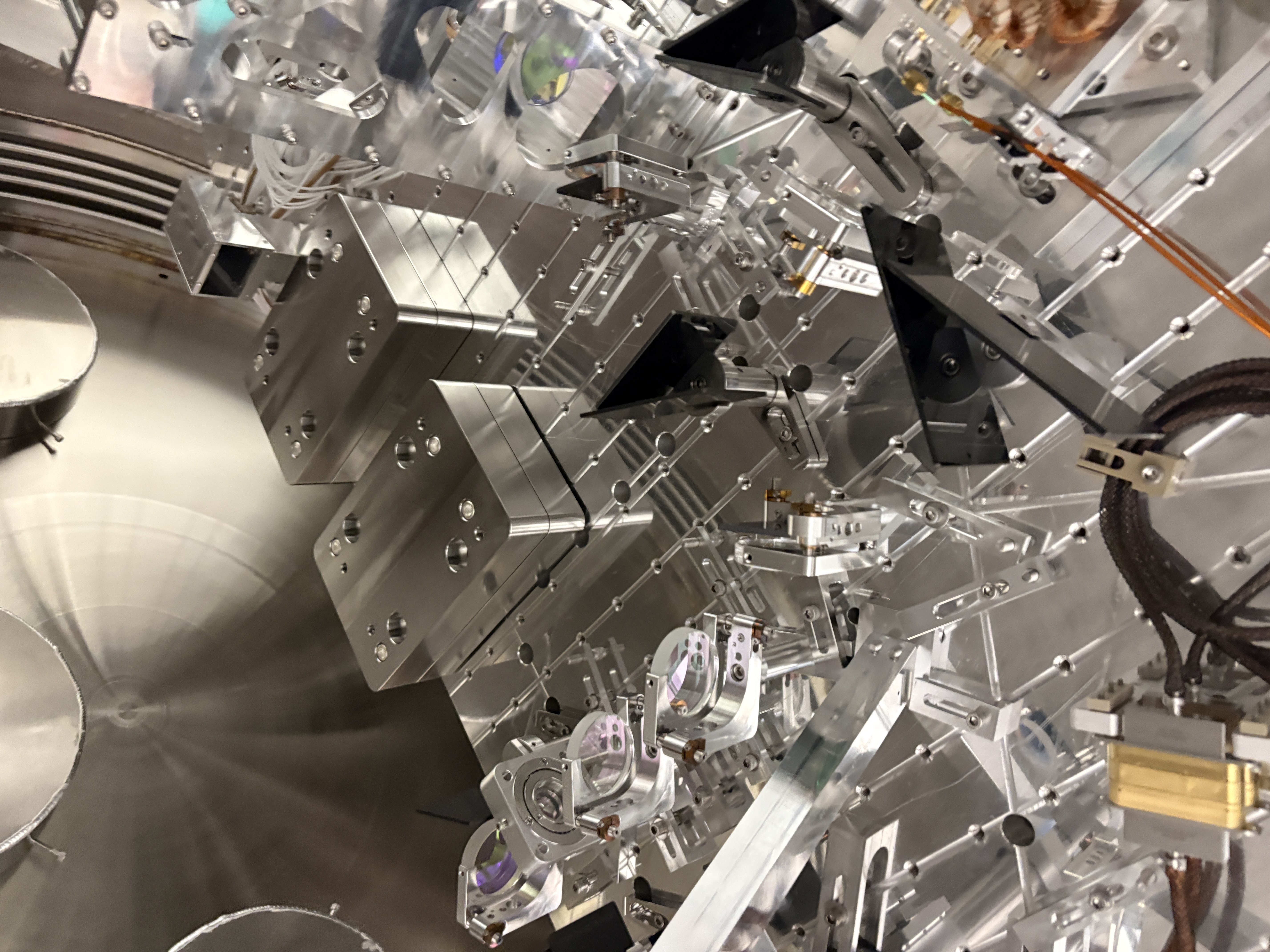
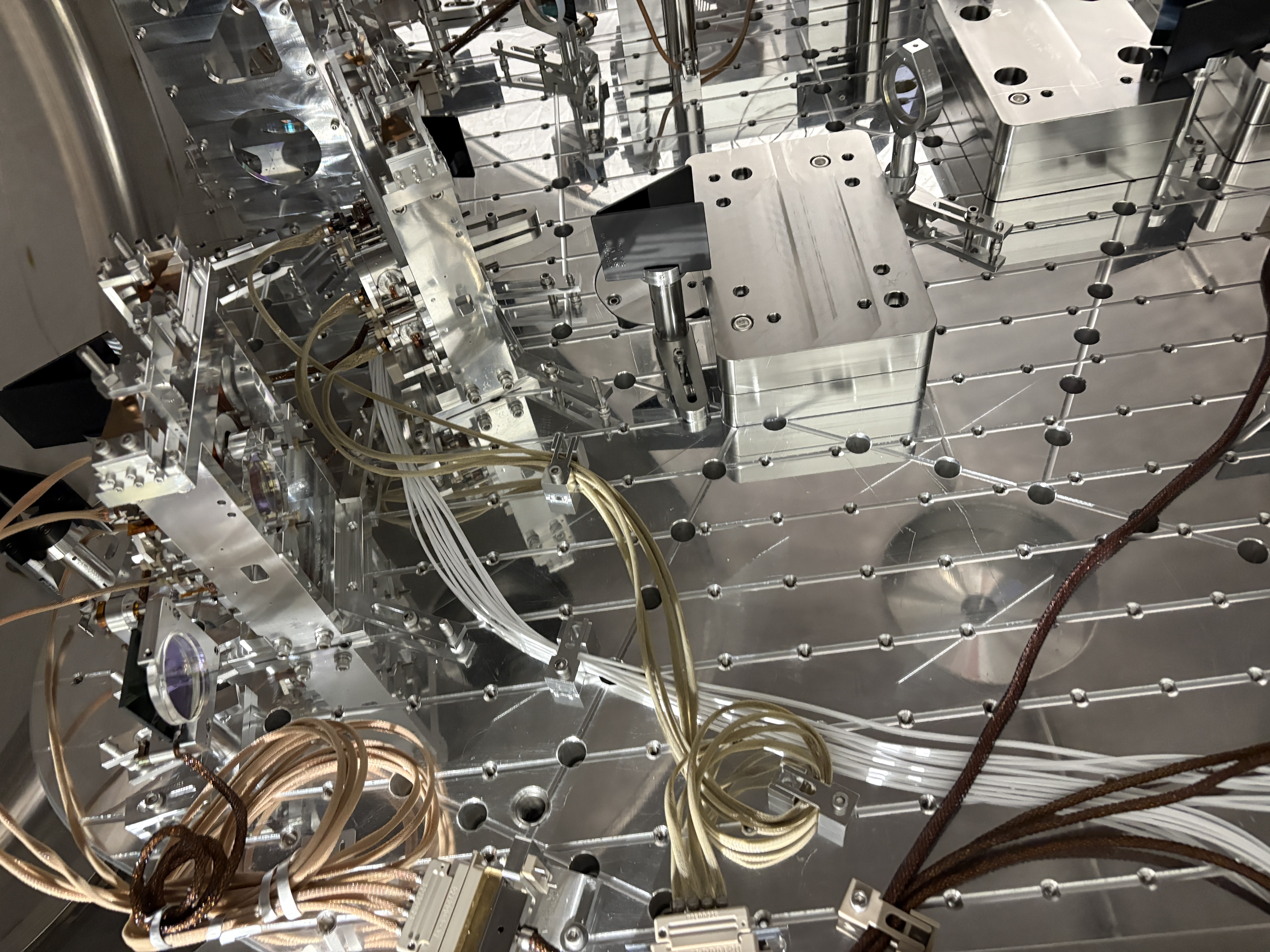
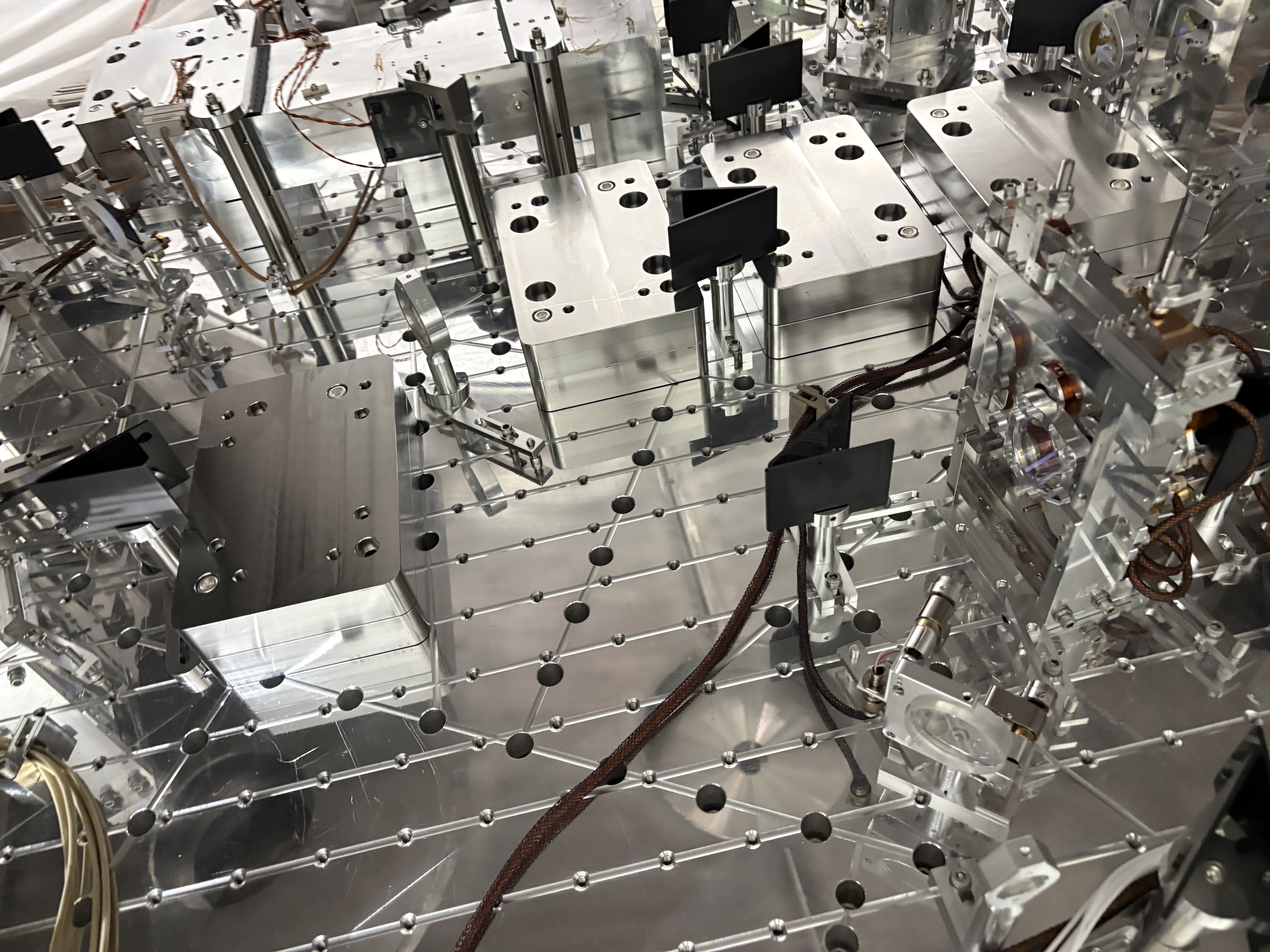
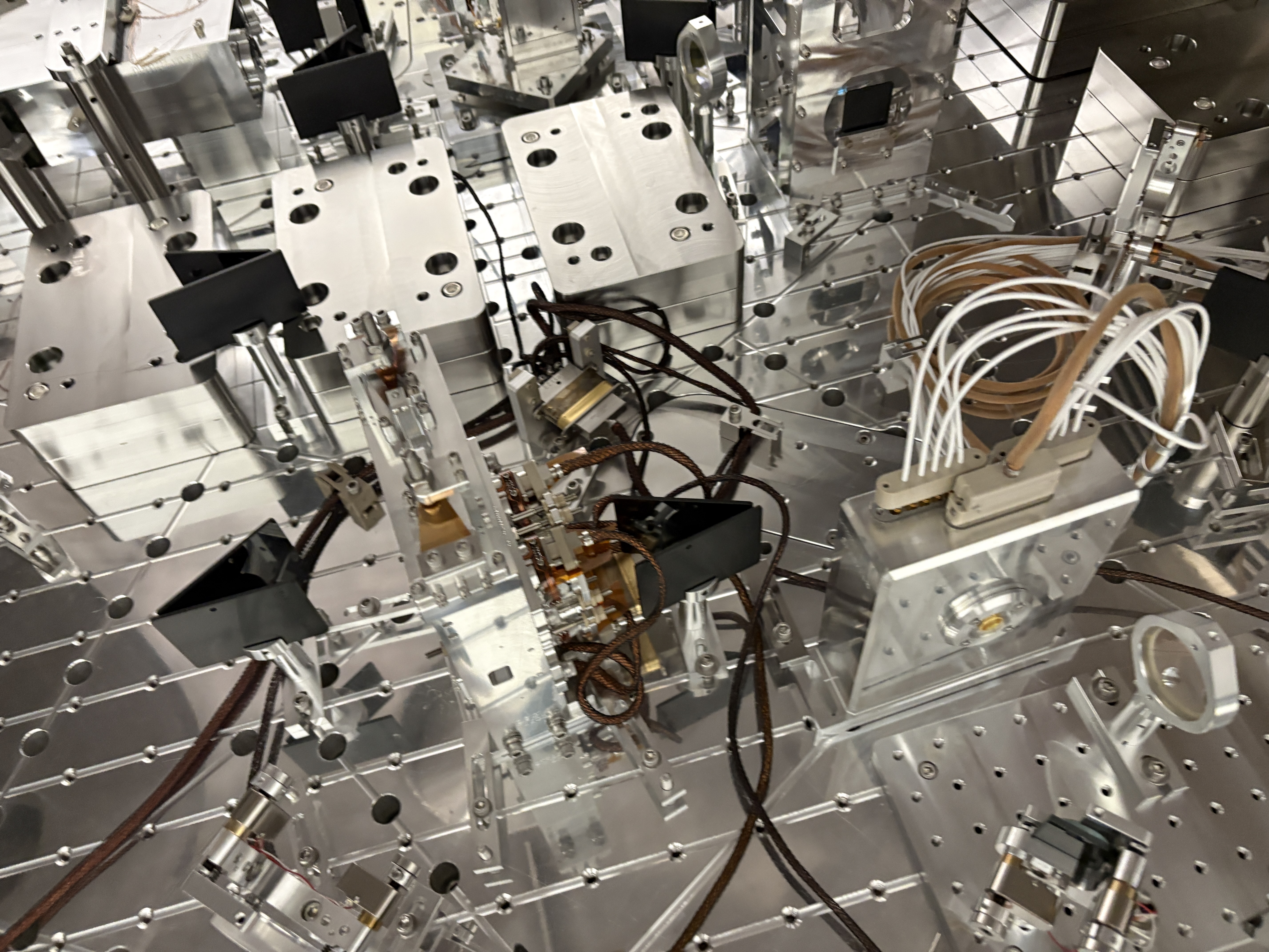
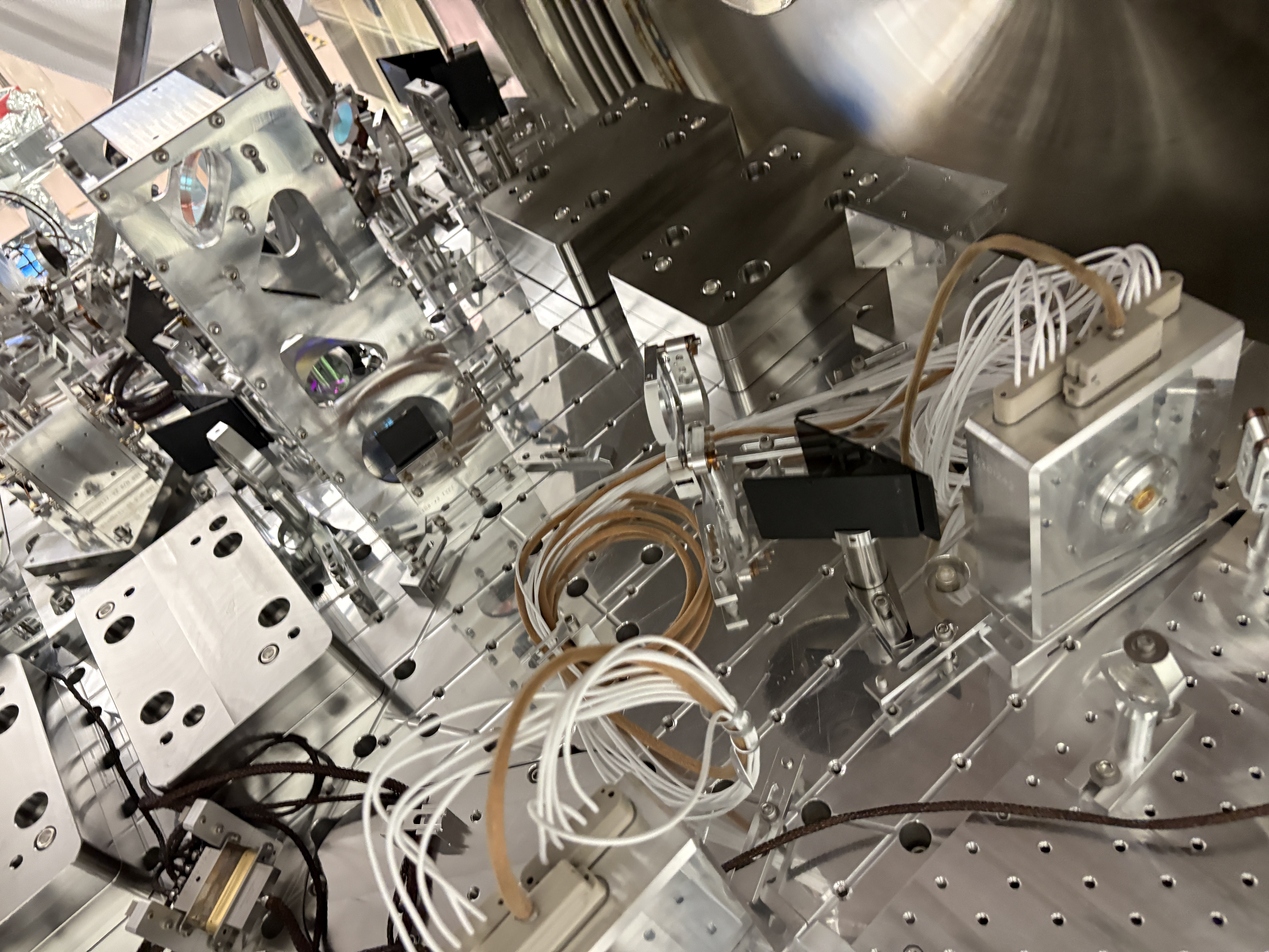
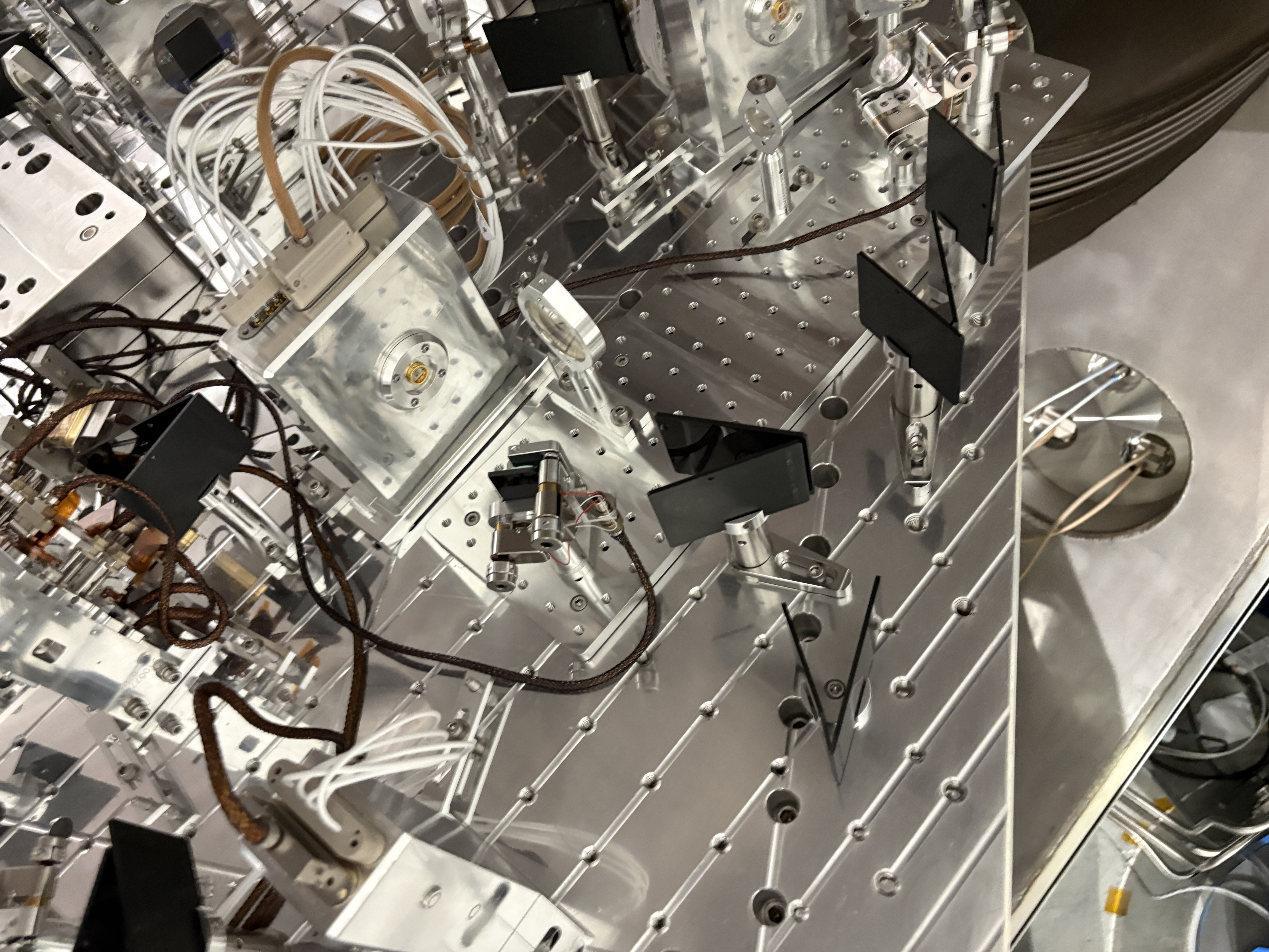
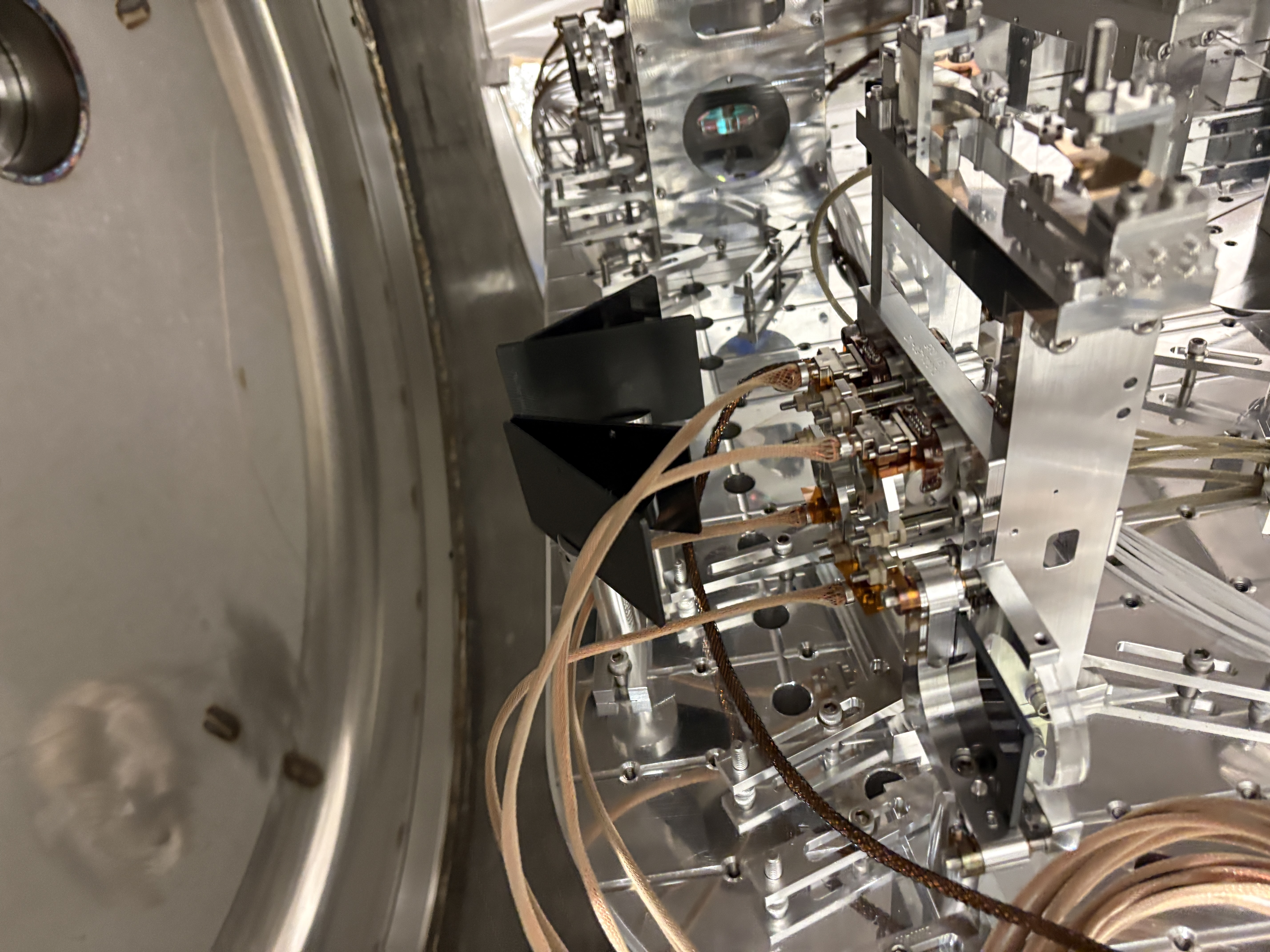
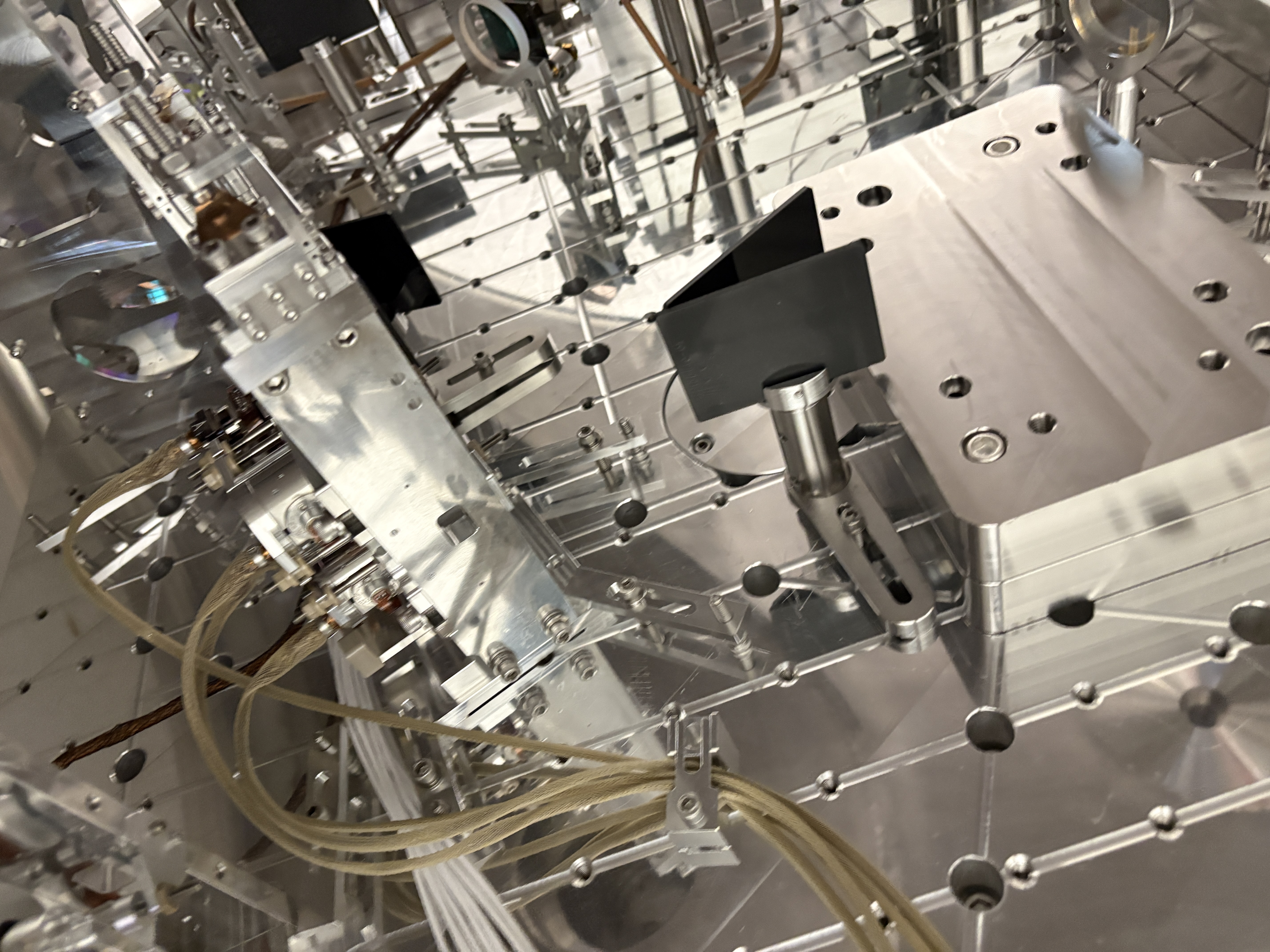
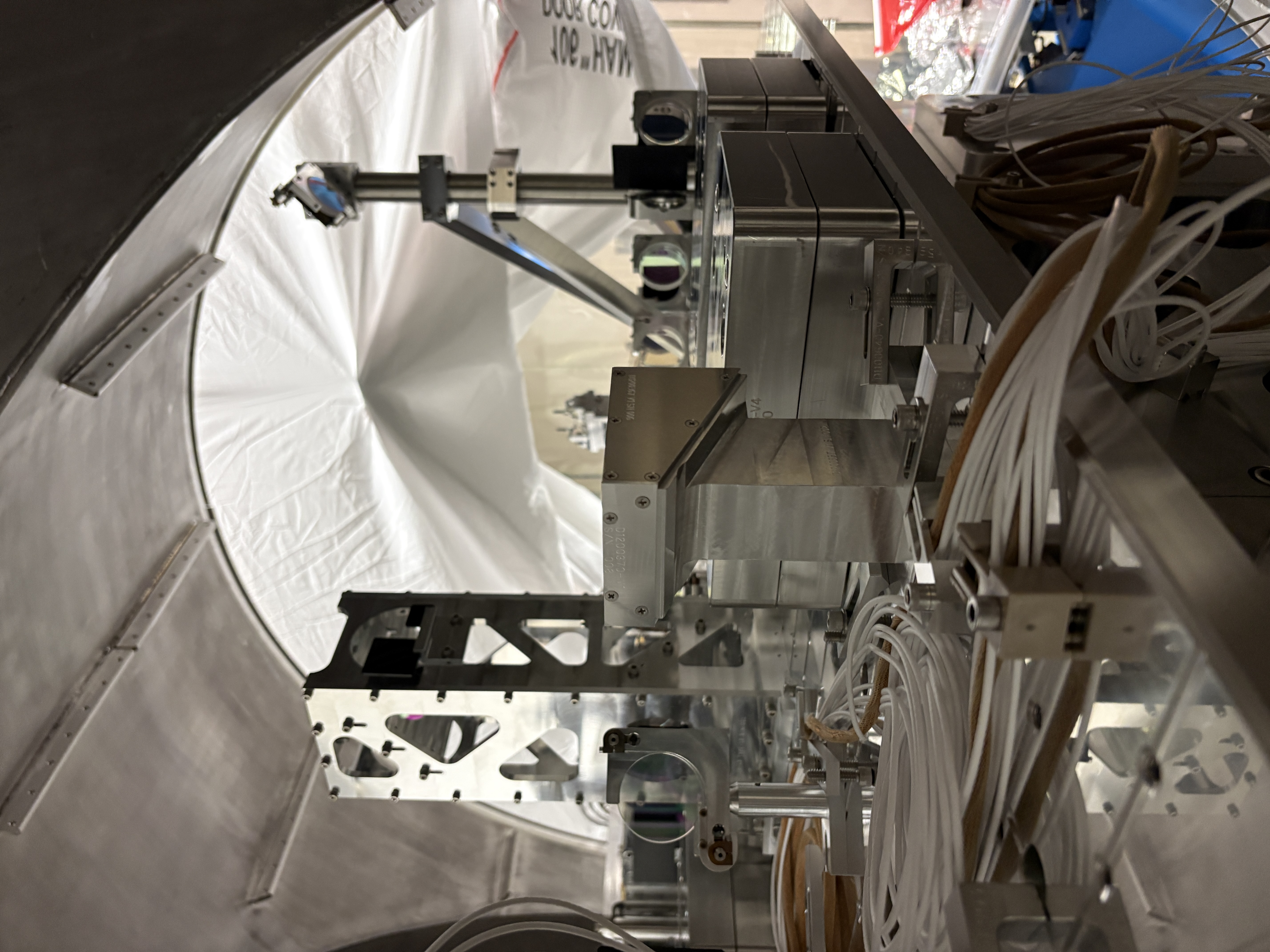
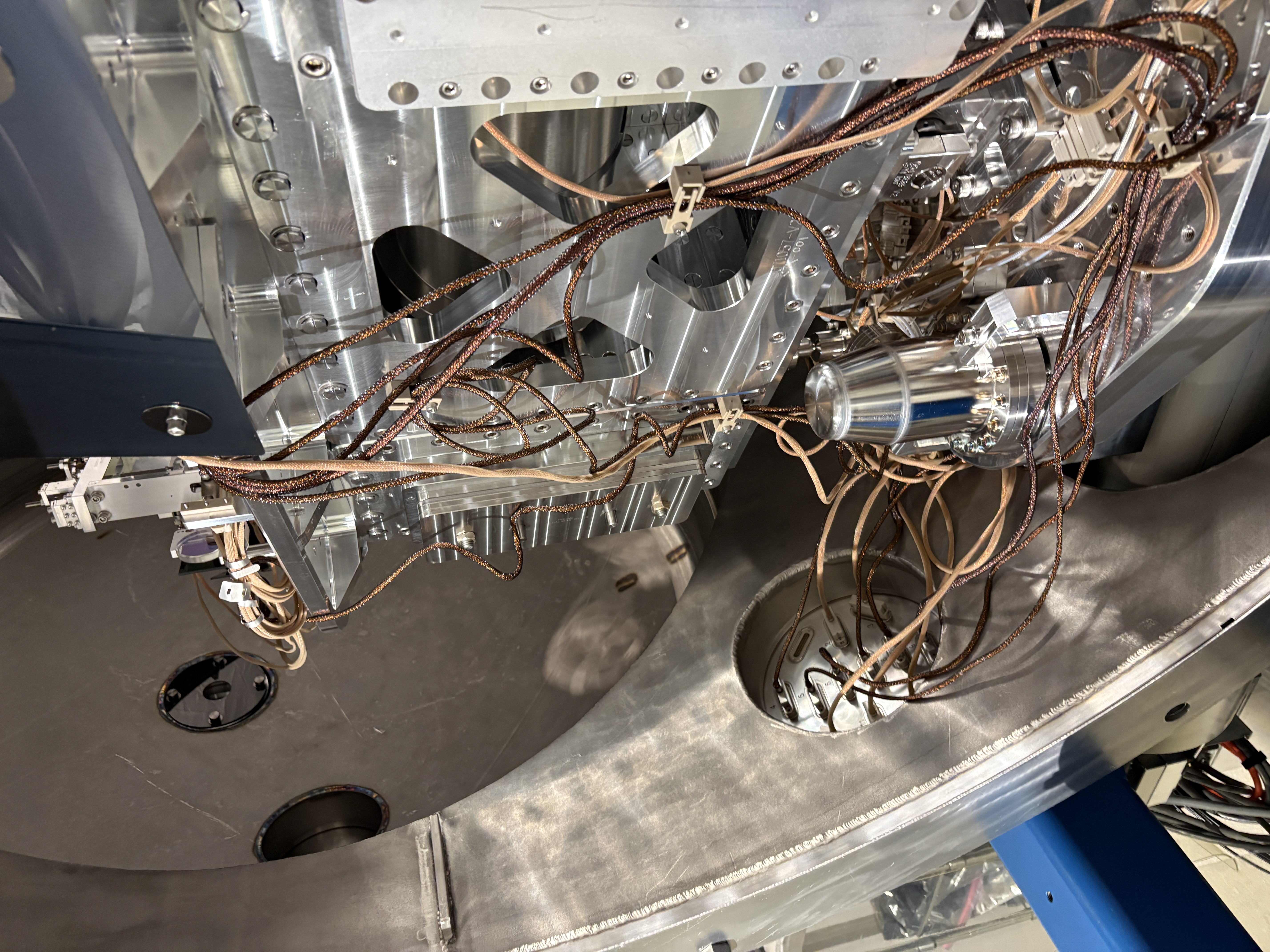
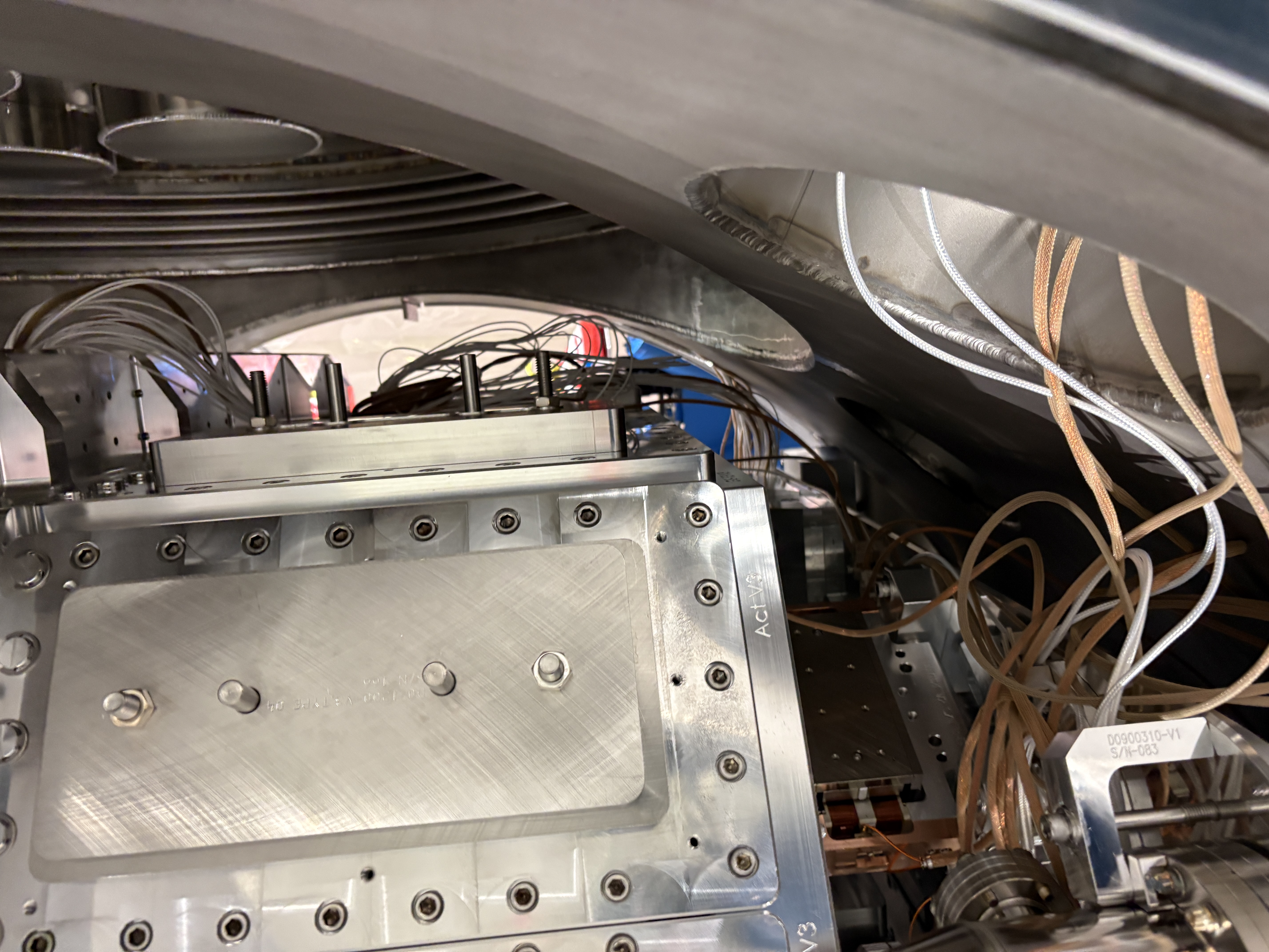
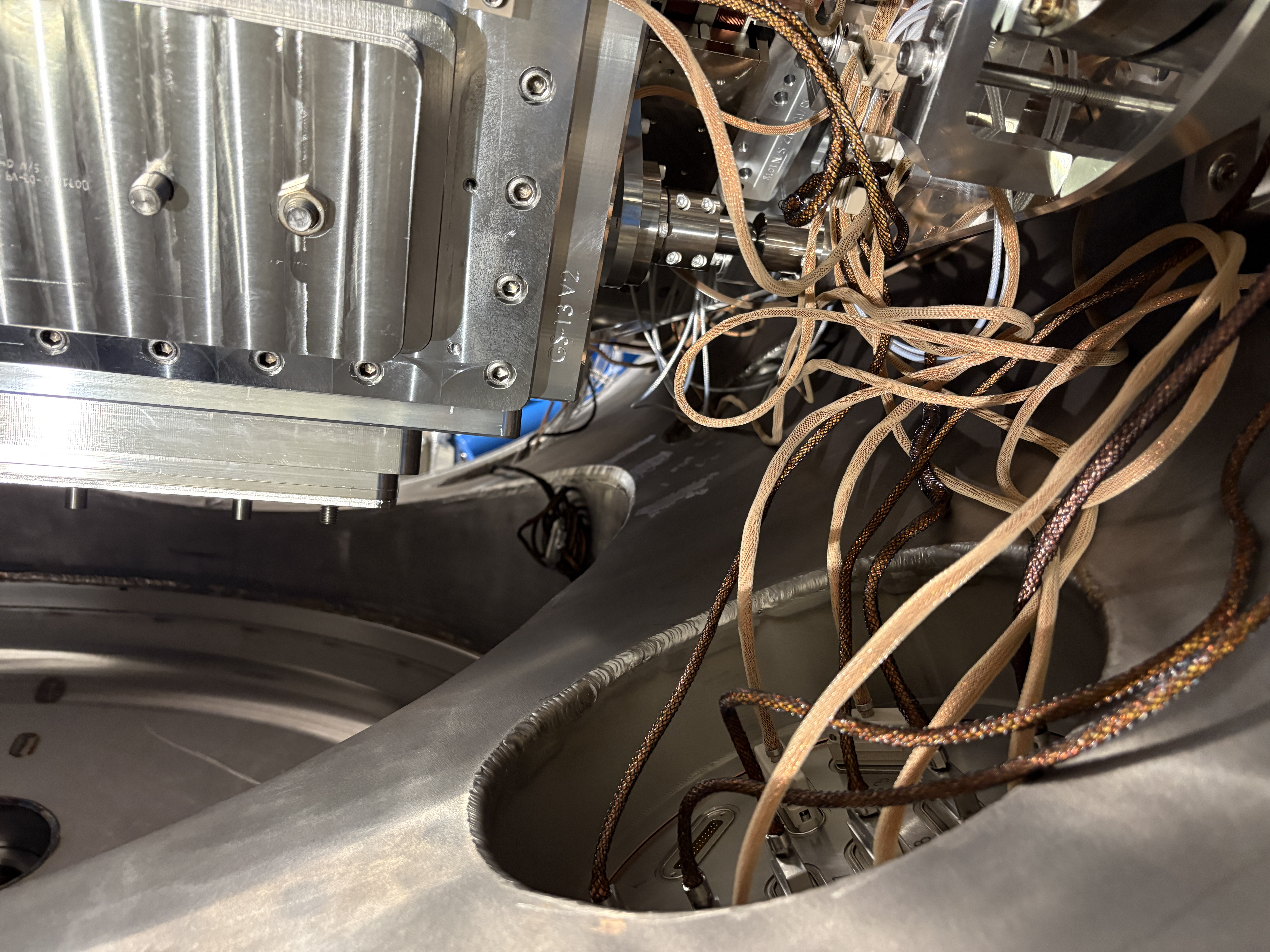
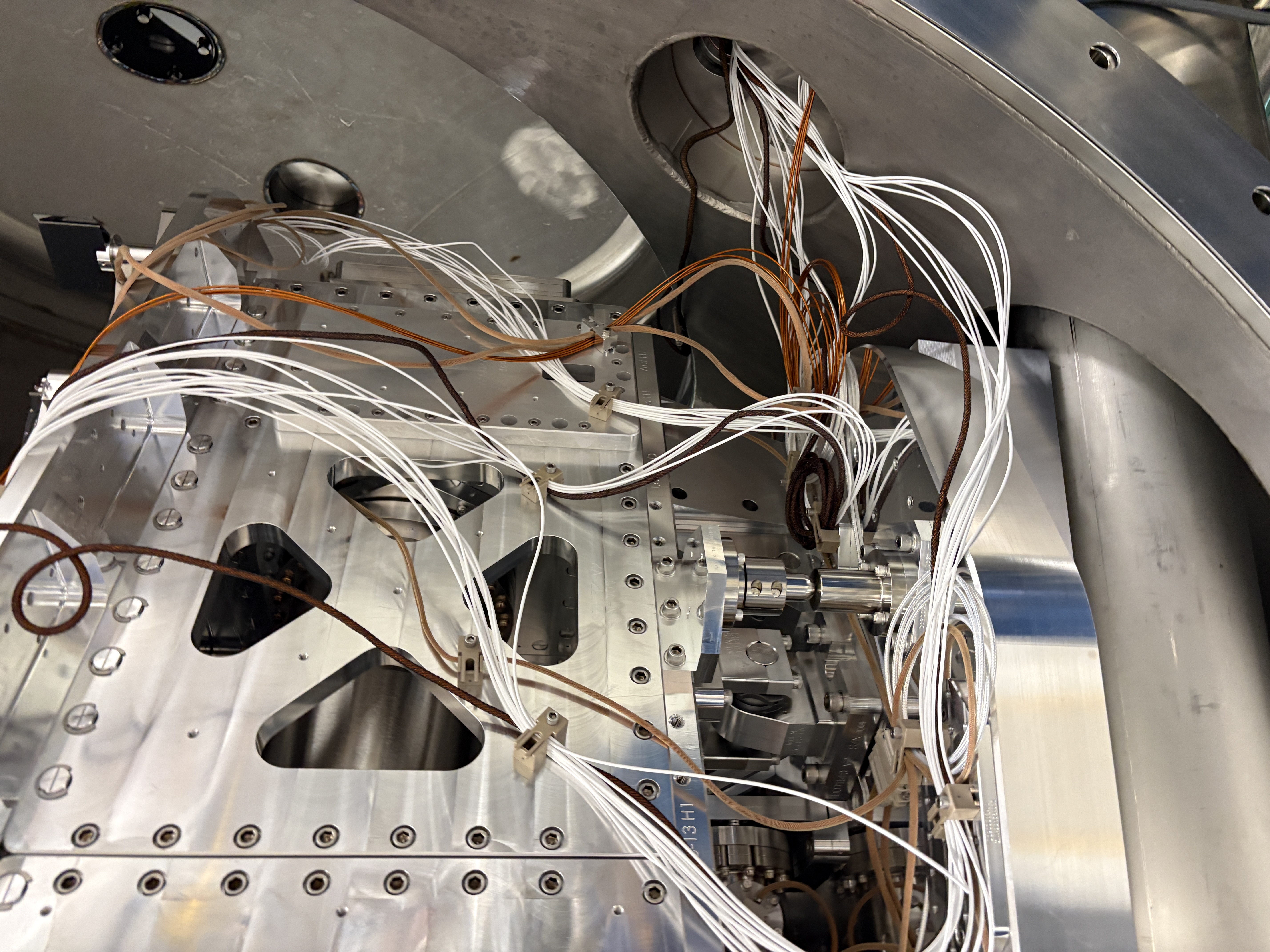
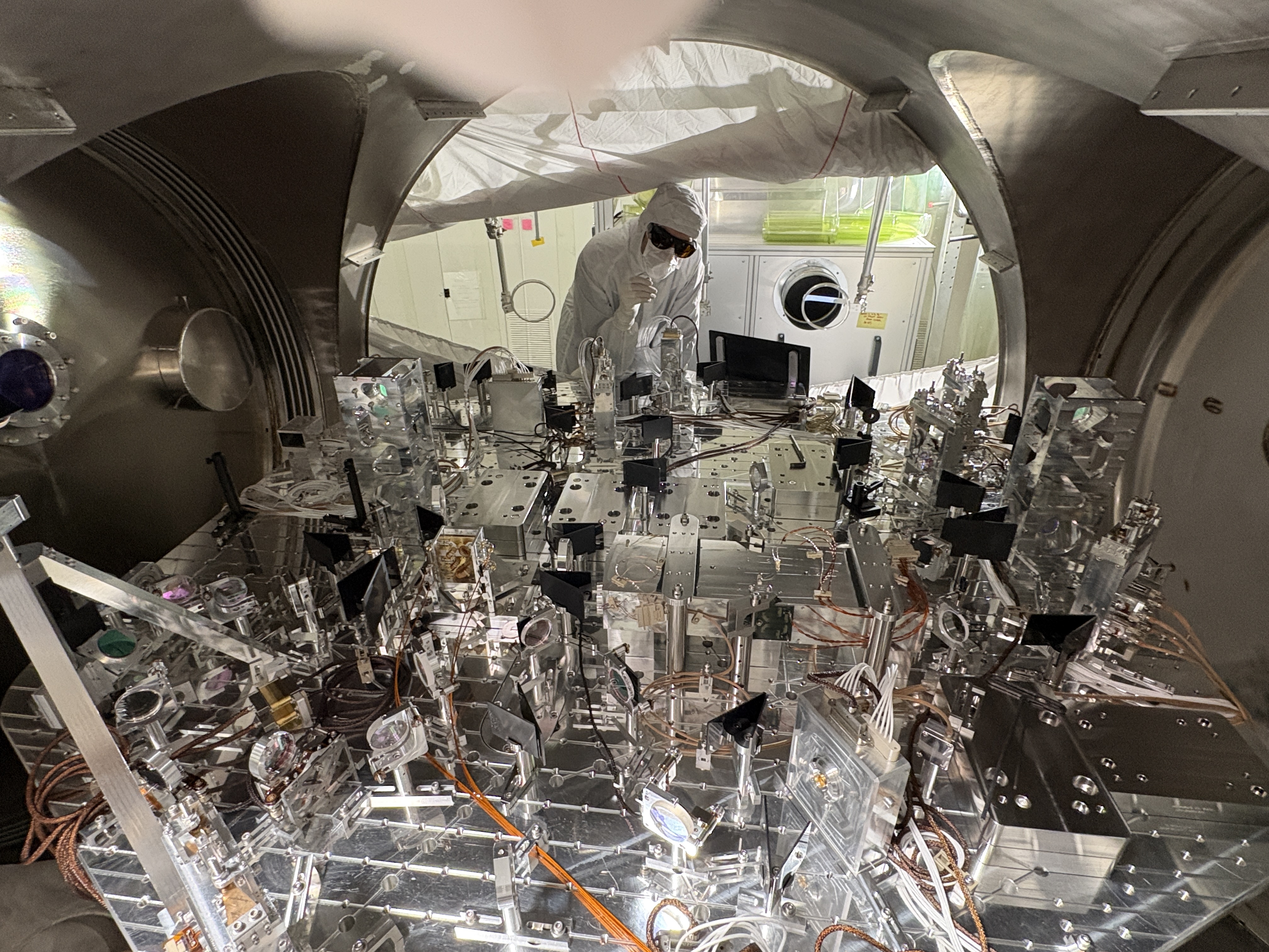
Sheila and Gabriele went and took some pictures of inside the HAM1 chamber, so keep an eye out for cool HAM1 pic filled alog.
We can consistantly get PRMI to lock. The Ryans are currently working on getting mich ACS to work.
LOG:
| Start Time | System | Name | Location | Lazer_Haz | Task | Time End |
|---|---|---|---|---|---|---|
| 15:06 | FAC | Randy | LVEA | N | Craning pedistols | 15:44 |
| 15:17 | FAC | Nellie & Kim | LVEA | N | Technical Cleaning | 16:20 |
| 16:08 | EE | Fil | LVEA | yes | Turning on Illuminator in HAM 1 | 16:23 |
| 16:21 | FAC | Randy | LVEA west bey | N | Craning some more. | 18:13 |
| 16:35 | FAC | Kim & Nellie | LVEA | N | Technical Cleaning | 17:04 |
| 16:36 | OPS | LVEA IS Birfurcated HAZARD | HAM1 | LOCAL | LVEA Bifurcated LASER HAZARD @ HAM1 | 18:17 |
| 16:40 | SPI | Jeff & Jim | Optics Lab | Yes | Building SPI | 23:04 |
| 16:47 | ISC | Betsy & Sheila & Jennie W | HAM1 | Yes | looking into HAM1 to find pointing issues. | 18:47 |
| 17:04 | FAC | Kim | Mid X | N | Technical Cleaning. | 18:09 |
| 17:06 | EE | Fil | LVEA Ham4 | N | Pulling Cables. | 18:36 |
| 17:10 | TCS | Sophie | Cheta Lab | Yes | Cheta-ing | 21:26 |
| 21:10 | ISC | Sheila & Gabrielle | LVEA HAM1 | yes | Photoshoot | 22:10 |
| 21:21 | SUS | Ibriham & Oli | LVEA | N | testing sus parts | 21:44 |
| 22:30 | VAC | Gerardo, Jordon | LVEA | N | getting a Vacuum cart | 22:52 |
| 23:40 | TCS | Sophie | Cheta | yes | Cheta work | 00:10 |
J. Freed
For the build of SPI, I measured the expected power output from a dual source Keysight 33600A through SPI's 2W amp D2500004. These measurements were taken with a E4418A EPM power meter using the HP 8484A 30dB attenuator attachment. After analyzing the data it is hard to say that the power meter power readings were accurate but the power the AOMs are receiving should be below the damage threshold of 33dBm.
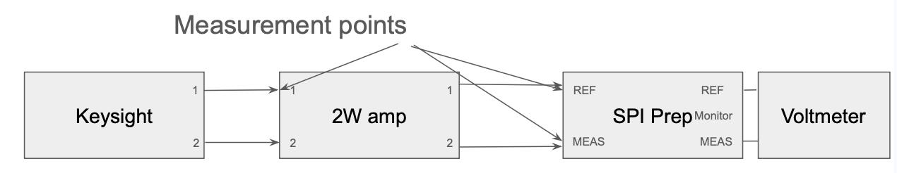
I measured the power at 2 points in the chain from Keysight -> 2W -> SPI prep, for both channels. (SPI_Build_RF_Diagram.png) The first point is just before the 2W amp, and the second point is just before the SPI prep for both channels. Then I compared that with what the output monitor voltage was showing on SPI prep for both channels.
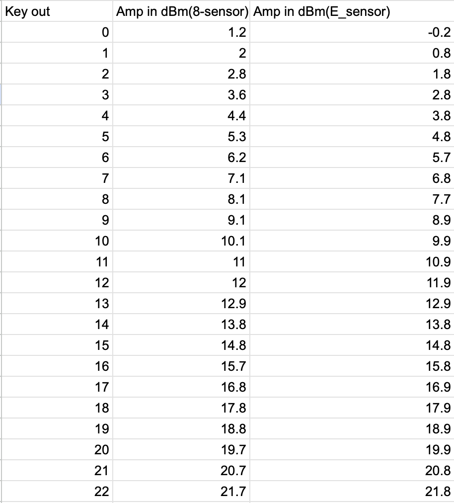
Power_Before_2W_Amp.png Is the data collected from power measurements just before the 2W amplifier. The limit of 22dBm is the limit of the keysight. From this it can be seen that there is not a 1-1 measurement between what the keysight says it is outputting and what the HP 8484A sensor is measuring. This difference is also changing based on the input power itself. With lower power overestimating what the keysight says its outputting, and higher power underestimating what the keysight says its outputting. This is a problem with the probe as switching out the probe to an E-series gives a relatively consistent error of -0.2dB between what the keysight says its outputting and what is being measured. Unfortunately the HP 8484A sensor is the only probe that can measure up to the 32-32.5dBm needed for SPI. Interpolating the results of the HP 8484A sensor up to 32 dBm gives approximately a 0.4dB underestimation of the power.
Then I took a measurement of the power after the 2W amp at the end of the cable that would plug into SPI prep. Namely I adjusted the power from Keysight, such that the output measured on the probe was 32dBm which is what SPI prep is expecting accounting for any possible underestimation of the power. Note that power past the 2W amp decreases over time (by about 0.5dB total) as the device warms up so I had to wait a couple of hours after start-up to take this measurement. The results were:
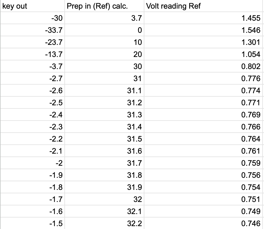
AMP 1 (Which goes into the ref path) measured 32dBm when the keysight displayed: -1.7dBm
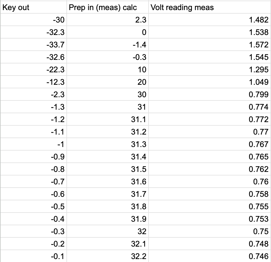
AMP 2 (Which goes into the Meas path) measured 32dBm when the keysight displayed: -0.3dBm
Be aware that that 32dBm has an error of +/- 0.5dB due to the factors listed above.
Then using the fact above, I found that the whole AMP 1 chain has a gain of 33.7 dBm from what the keysight displays. And AMP 2 chain has a total gain of 32.3dBm from what the keysight displays. Using this fact I could find the voltage associated with each of the monitor channels of SPI prep.
Monitor_read_AMP1_REF.png and Monitor_read_AMP2_MEAS.png show the monitor reading voltage vs the approximate input RF power into SPI prep. for both channels. Interpolating the results gives a calibration equation between RF power and monitor voltage of:
AMP 1 (REF): [V] = -0.0249*[dBm] + 1.5480
AMP 2 (MEAS): [V] = -0.0246*[dBm] + 1.5387
With both channels reaching 32dBm around 0.75V on the monitor channel this gives an easy target for controling the power.
J. Kissel
Easy look up table after setting up Keysight 33600A per T2600039, and setting the amplitudes as we have had for most of the build ::

CH1 = AMP 1 = REF = M2 MON
    f = 79.995904 MHz (79,995,904 Hz)
    amp = -1.7 dBm
    M2 MON = 740 mV

CH2 = AMP 2 = MEAS = M3 MON
    f = 80.000000 MHz (80,000,000 Hz)
    amp = -1.4 dBm
    M3 MON = 755 mV

Remember to turn the output ON for each channel.
Betsy, Sheila, Jennie W,
This morning Betsy and I removed the viewport cover on the -Y, -X upper port of HAM1. We pointed a laser pointer at REFL WFS A and B, and saw similar DC counts on each of them, with WFS A channels responding when I pointed the laser pointer at the +X diode and WFS B responding to the the -X diode. We were also able to point the laser pointer at LSC REFL B and LSC POP, and both responded. We can't reach LSC REFL A, but we know that diode is responding. POP X is not easily accessible this way, although we might be able to reflect off PM1 to hit that diode.
Jennie W and I went back with the Nikon D810 from Keita's office. We expirimented with different settings on the camera, and taking photos with illuminators and table lights on and off. A few photos are attached, you can see IR light on the barrel of the beamsplitter that splits the beam between WFS A and WFS B. There is also a glint on the mount of the second lens on the sled.


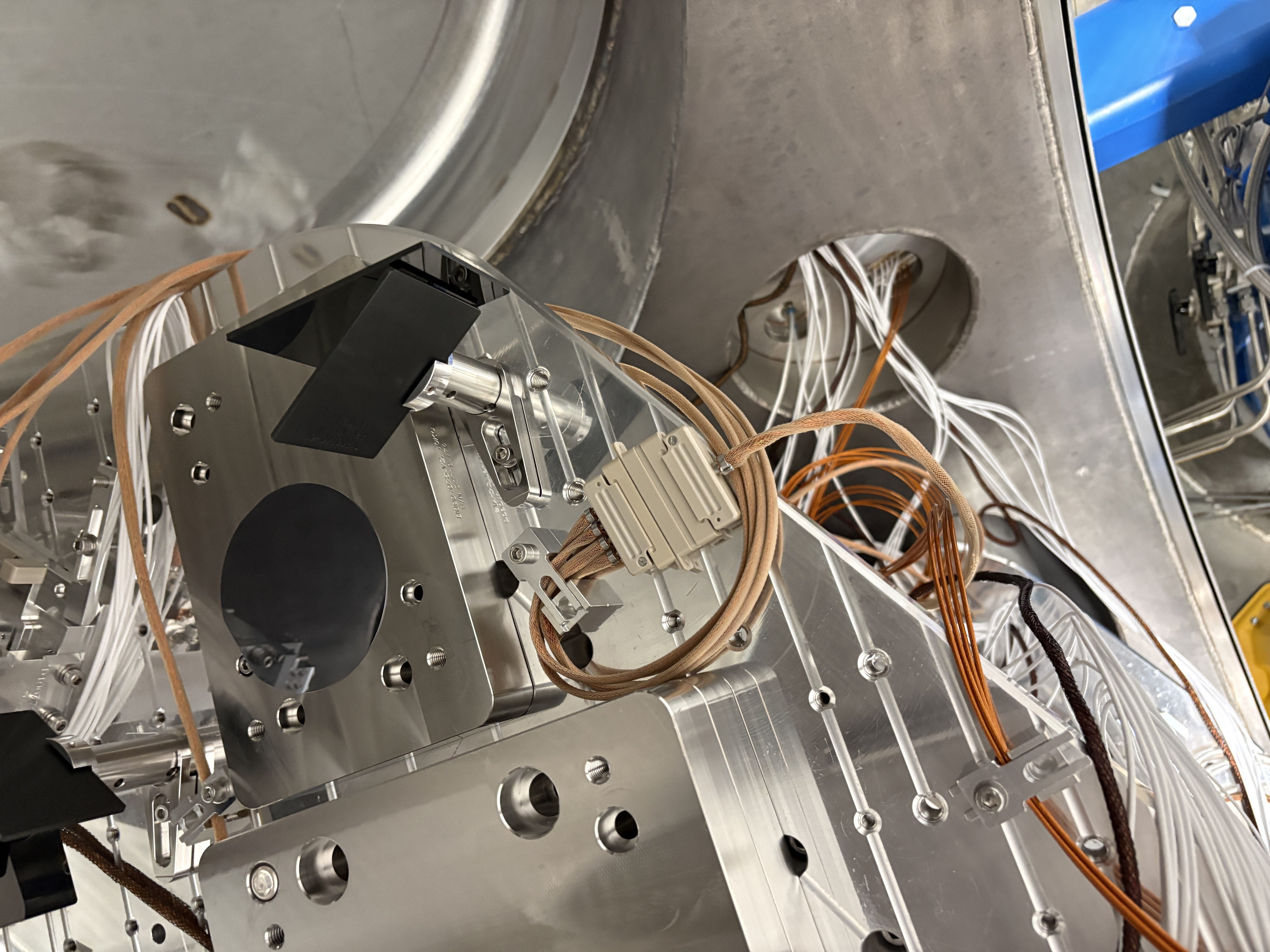
Gabriele and I went out and took some more photos. We also pulled the viewport cover from the +Y -X side of the chamber, (the lower level), and we have a side on view of POP X. We saw a signal when we pointed the laser pointer at the diode. We ran a raster on PM1, but do not see any beams. We also took some photos of LSC POP from the other side of the chamber, these also show no beams. (LSC showing no beam and a tiny glint above and in the +x direction from the diode, caught twice. )
We also took some photos of the LSC pop diode with the illuminator off, they are just black.
We got photos of the glint of the REFL WFS sled BS, with and without offsets on RM2, they look about the same. (here and here)


Upgraded the main slow controls software to add some calibration features for CHETA.
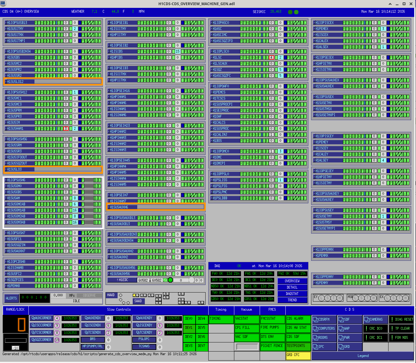
I've reworked the CDS Overvew MEDM for the HAM6 changes.
The additional corner station SUS models have increased the SUS column's height (first column). To accomodate I've moved the WATCHDOG section over to the second (SEI) column, below the consolidated SUSAUX section.
The DAQ section has been moved to the 3rd column (ISC).
The new h1sush6 front end, highlighted in WHITE, is not currently in the DAQ, hence the grey'ed DAQ status.
Placeholders for the LO12, LO3 and SUSAUXH6 models are highlighted in ORANGE.
I think this overview contains all the additional parts needed for IR1.
Mon Mar 16 10:10:45 2026 INFO: Fill completed in 10min 42secs

FAMIS 31129
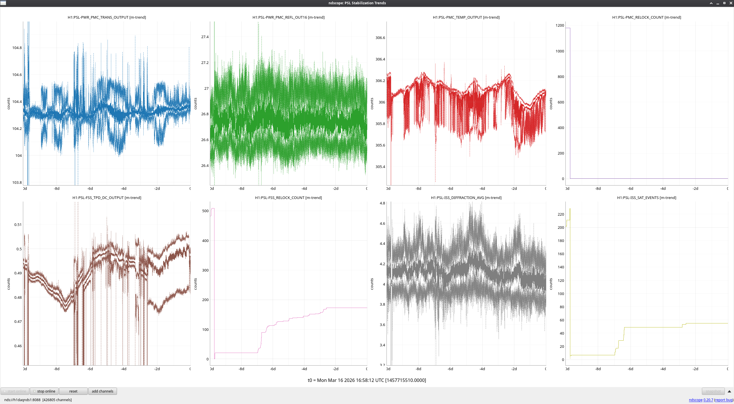
The IMC was left 'DOWN' at the end of last week, so as it naturally flashed through resonance, the FSS was being pushed on a bit, which explains the noisy FSS TPD signal over the weekend. Once the IMC was locked this morning, this behavior stopped. No other events to report this week.
TITLE: 03/16 Day Shift: 1430-2330 UTC (0730-1630 PST), all times posted in UTC
STATE of H1: Planned Engineering
OUTGOING OPERATOR: None
CURRENT ENVIRONMENT:
SEI_ENV state: CALM
Wind: 6mph Gusts, 4mph 3min avg
Primary useism: 0.03 μm/s
Secondary useism: 0.30 μm/s
QUICK SUMMARY:
Seems to me like it's a good day to Lock and IFO.
Beam splitter ISI had a wtchdog tripped when I came in.
There are a few things that seem a bit off with the ISI Like: the ISI_BS_ST1_SC Guardian is white like it can't load something. The CPS blends have White boxes in them. FF01 & 12 , ST 1 & 2 ISO , all contain red boxes.
HWWD stat button is white. Spoke to CDS team Dave Said the ISI_CUST_CHAMBER_OVERVIEW screen needs to be updated to show the ISI_BS_ST1_SC Guardian correctly. As there may be an error on that screen.
Locking Notes:
Took ISC_LOCK to Manual_INTIAL_ALIGNMENT
Aligning Green arms:
X arm is only around 0.4 after my best attempts to align it. I may double the H1:ALS-C_TRX_A_LF_OUT16 value. to get past Locking IR.
Y arm however has fantastic flashes.
Requested ALIGN_IFO to PRC_ALIGN_OFFLOADED & Got Stuck at WFS_CENTERING_PRX.... maybe we are't yet able to use the WFS?
Took ALIGN_IFO back to init then PRX_ LOCKED, Made it there. then to Down, then to MICH_BRIGHT_OFFLOADED.
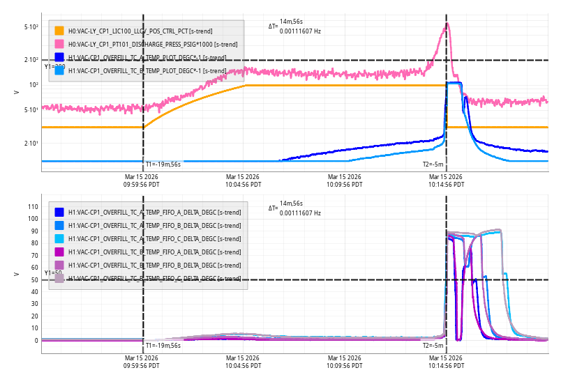
Sun Mar 15 10:14:56 2026 INFO: Fill completed in 14min 52secs
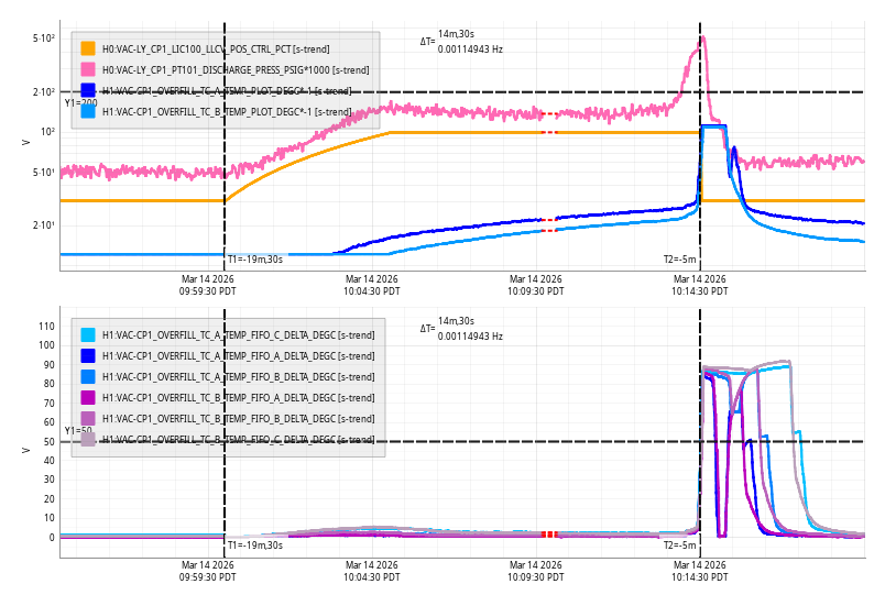
Sat Mar 14 10:14:30 2026 INFO: Fill completed in 14min 27secs
The JAC heater turned on at 8:00 PM PT. JAC-HEATER_POWER_SET is set to 3.
TITLE: 03/14 Eve Shift: 2330-0500 UTC (1630-2200 PST), all times posted in UTC
STATE of H1: Planned Engineering
INCOMING OPERATOR: None
SHIFT SUMMARY: I touched up DRMI alignment but we're still having issues with DC centering.
LOG:
| Start Time | System | Name | Location | Lazer_Haz | Task | Time End |
|---|---|---|---|---|---|---|
| 23:24 | Cheta | Sophie | Cheta Lab | local | Workign on Cheta | 00:42 |
| 00:27 | OPS | Oli | LVEA | LOCAL | Unplug laptop charger | 00:33 |

I did the monthly wind fence inspection yesterday. No new issues. Damage to the one panel at EY seems stable, no damage noted at EX.


Tagging For EPO.
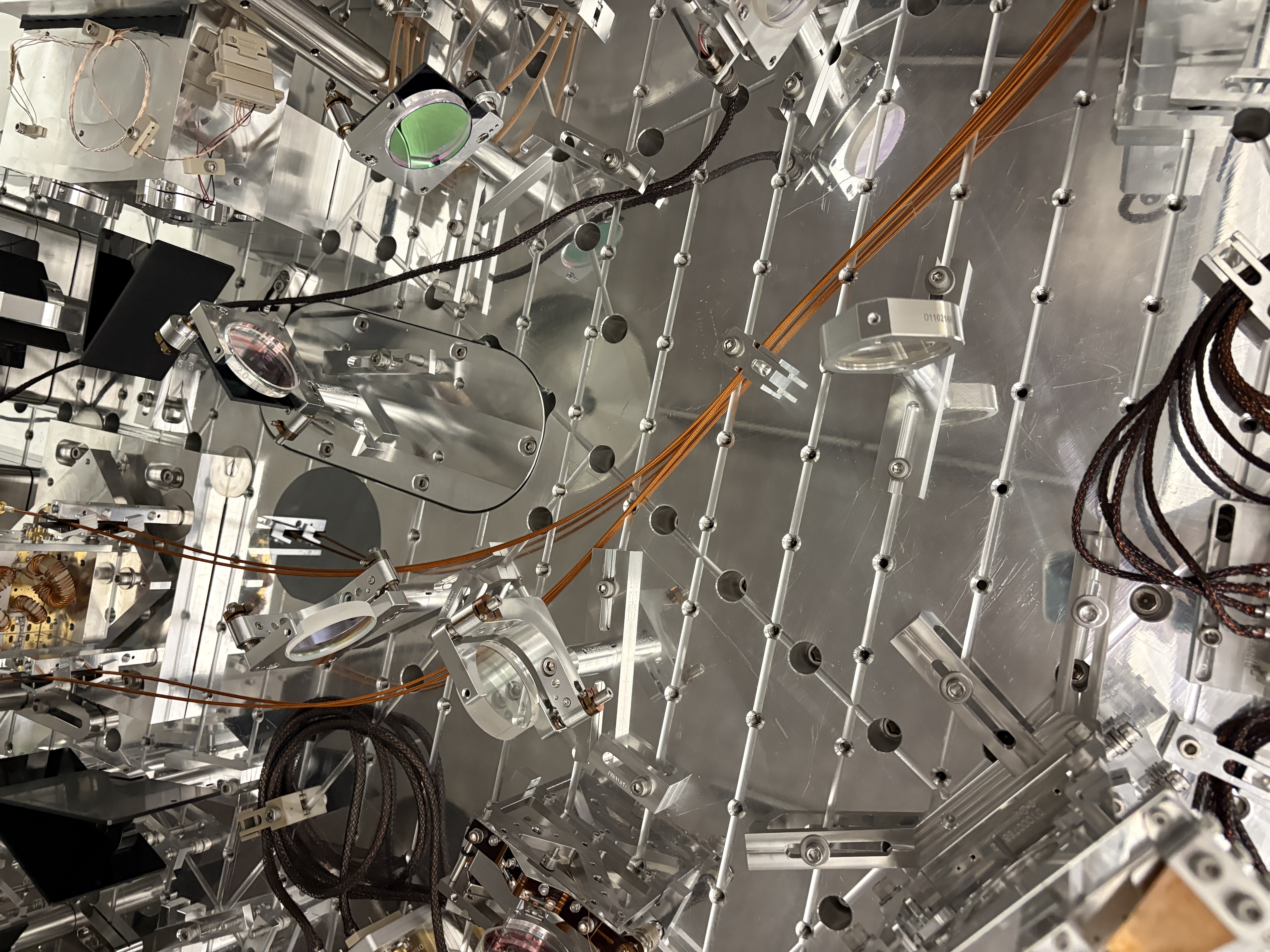
Yesterday, ground loop checks revealed a new and random ground loop issue on the LR BOSEM of the Tip Tilt PM1 suspension (which has been installed and used in vac for a long while now).  This morning I worked to swap the BOSEM for a new one, reset the medm offset/gains and recentered.  Fil confirmed that the ground loop situation is now resolved on PM1.  In Corey's absence, I took a bunch of photos (won't be as good as his but here for posterity) of the chamber components as we see them before closing up.  I wiped down some of the under table surface as I could.  Jim and I both inspected for left behind items on and under the table.
BOSEM SN 263 is the problem OSEM removed, SN 229 was swapped in with OLV 28860.

Jim then removed the septum viewport covers (all 4)and unlocked the ISI.  Oli ran the final closeout TFs for PM1 (JM1 and JM3 were yesterday).  I revisited the closeout check sheet and we launched the door crew (Jordan, Randy, and FAC - thanks for jumping in due to others absences!).  1 door is on now and we are about to check that the JAC Refl beam goes through the viewport on the door as anticipated given the inaccuracy of the viewport simulator fixture.
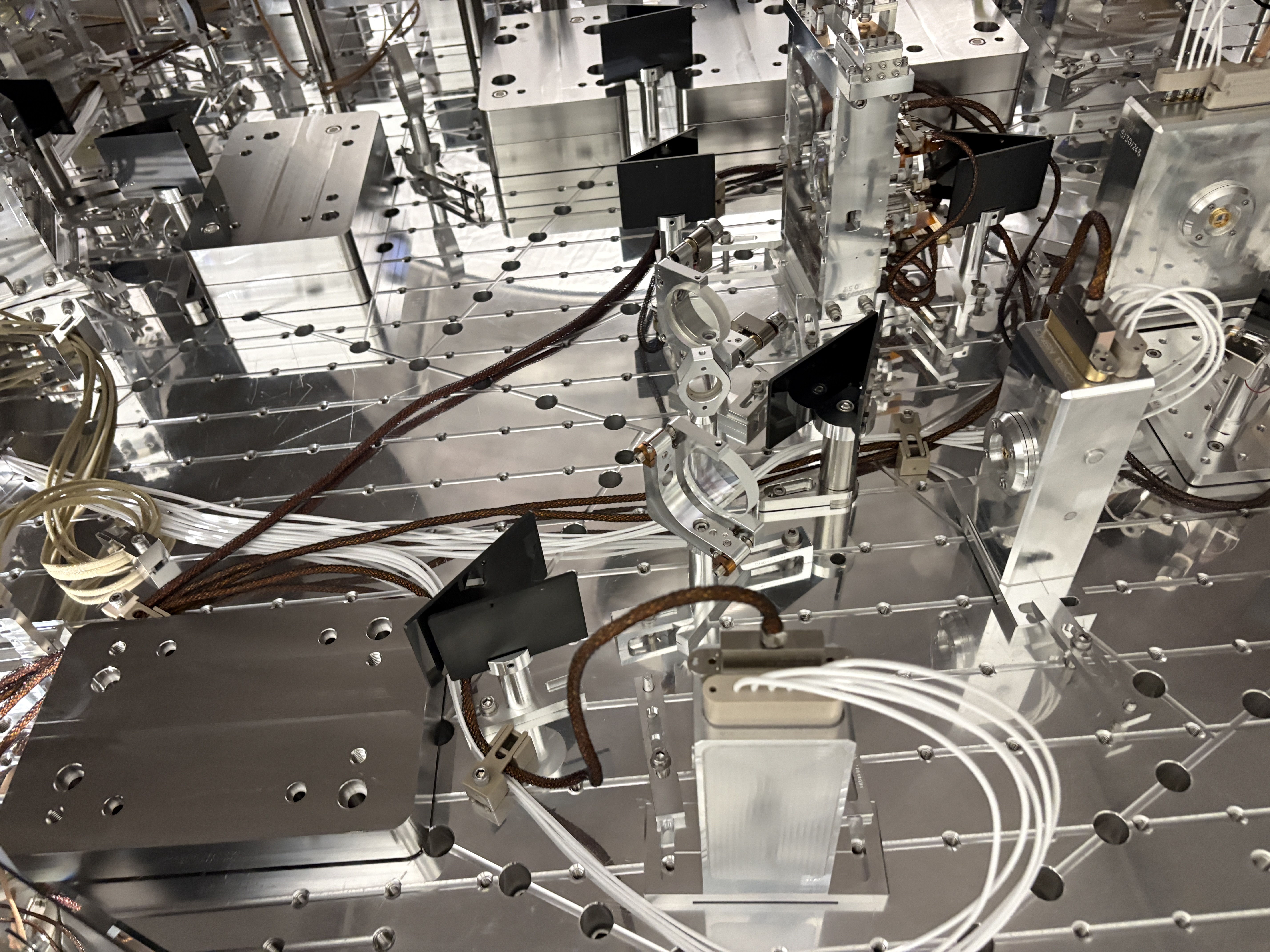
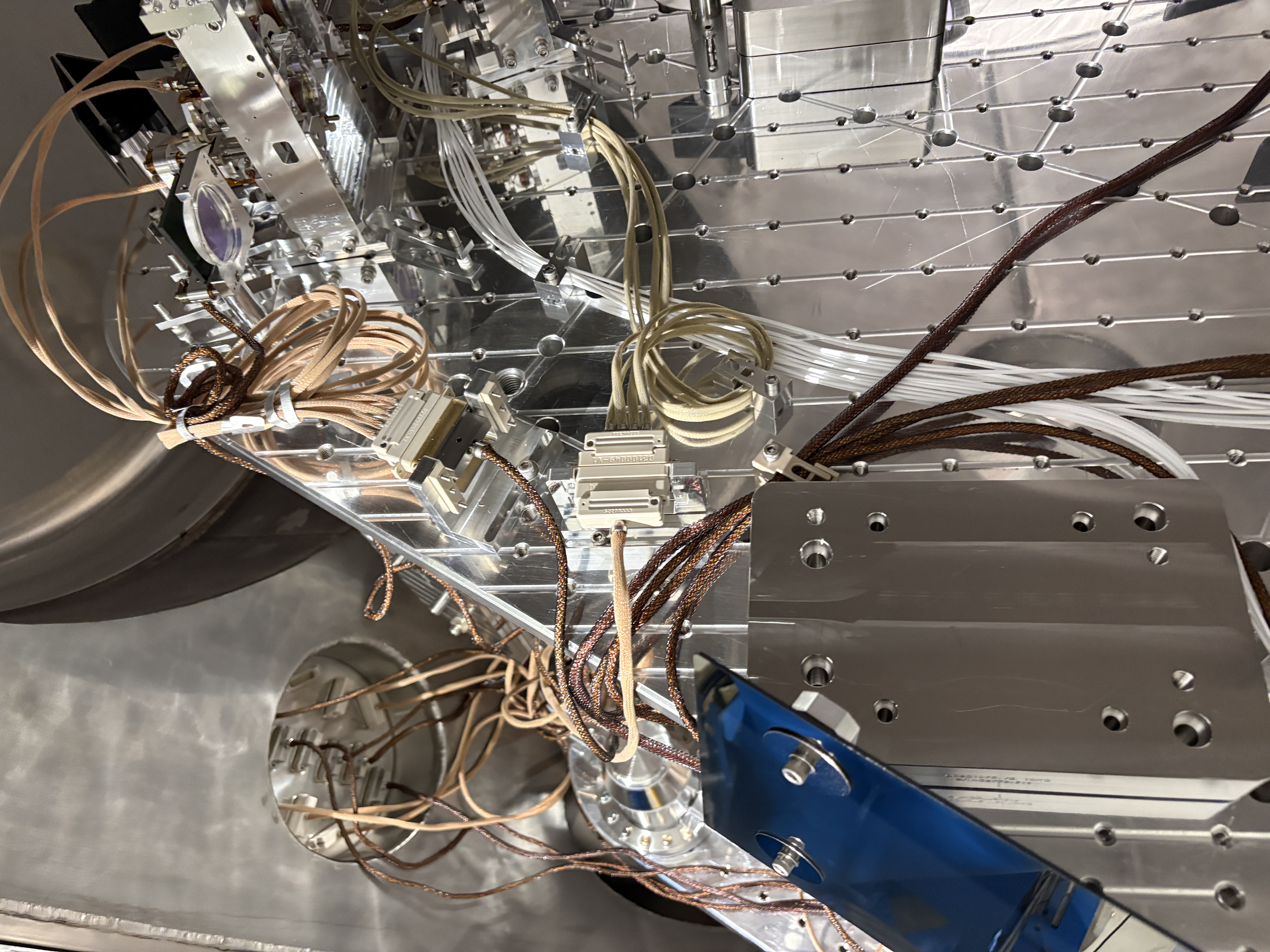
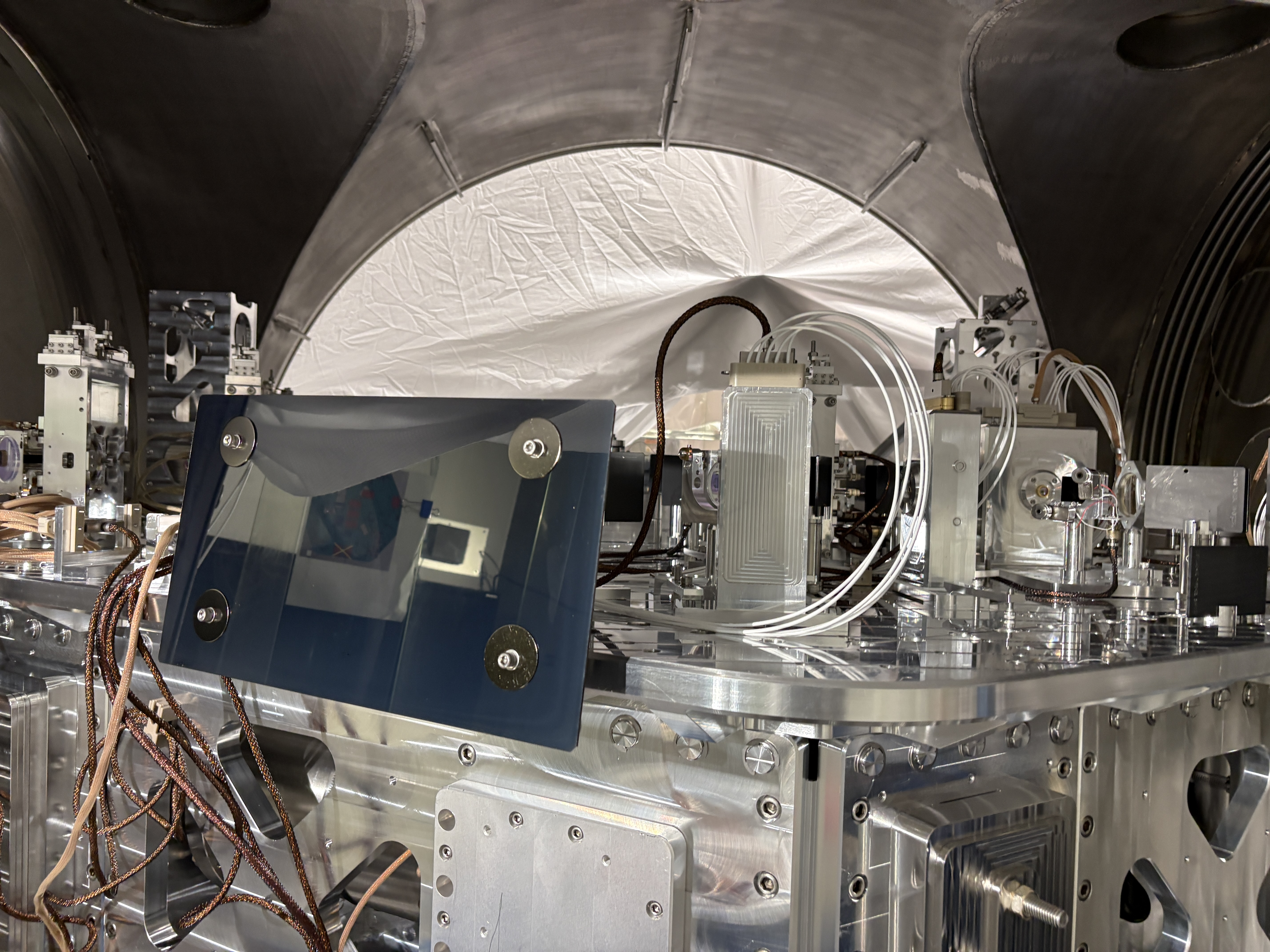
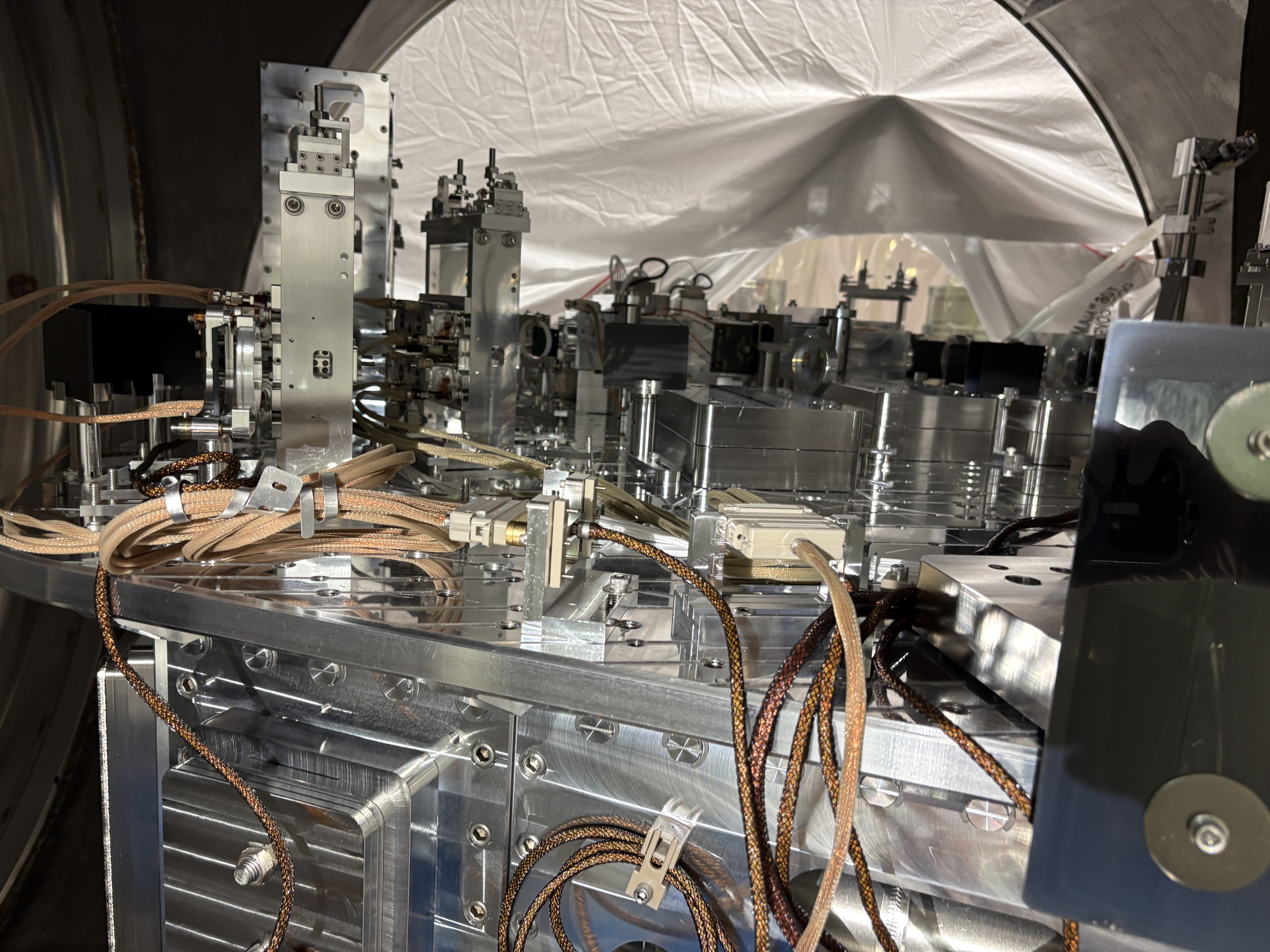
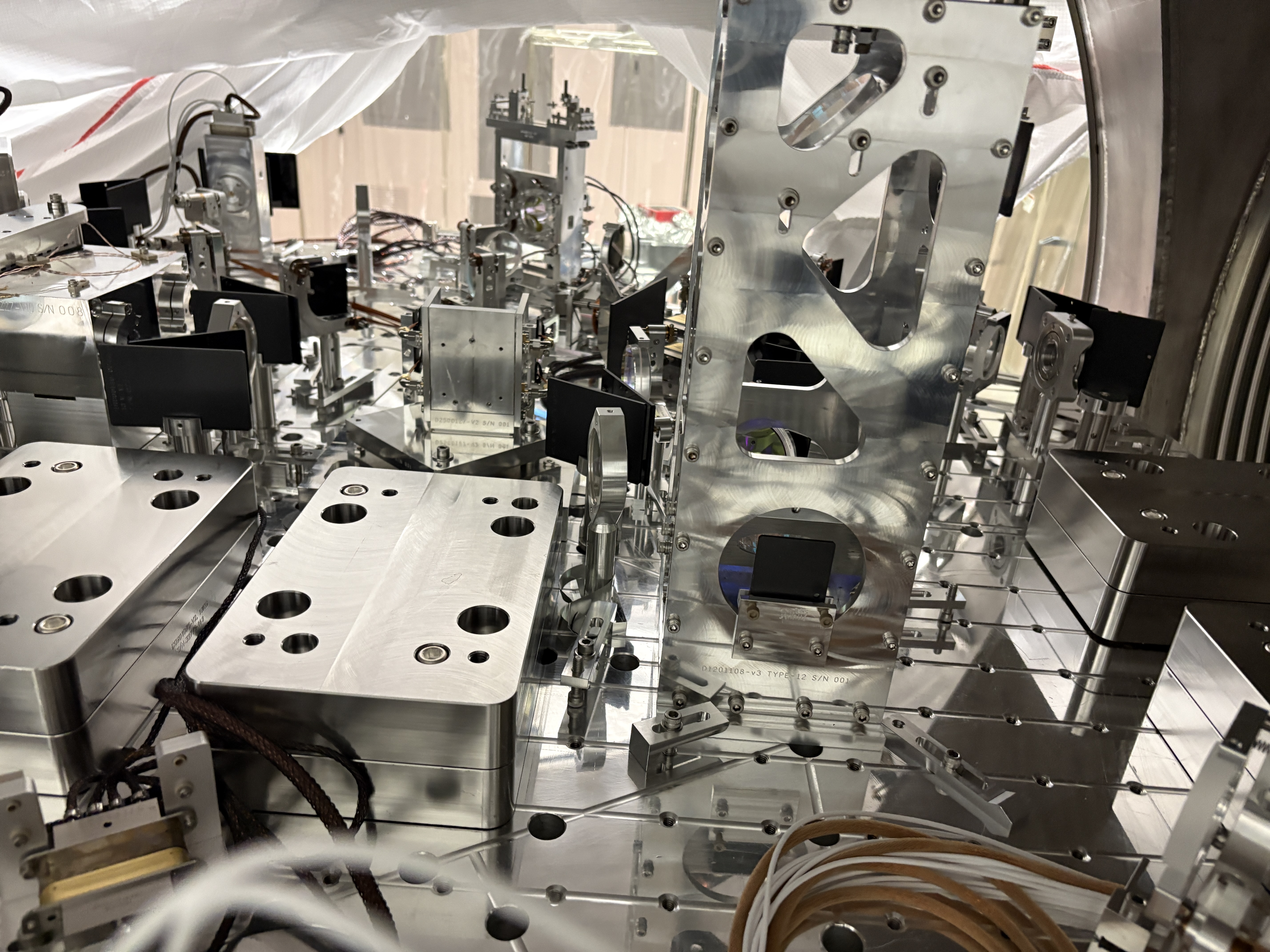
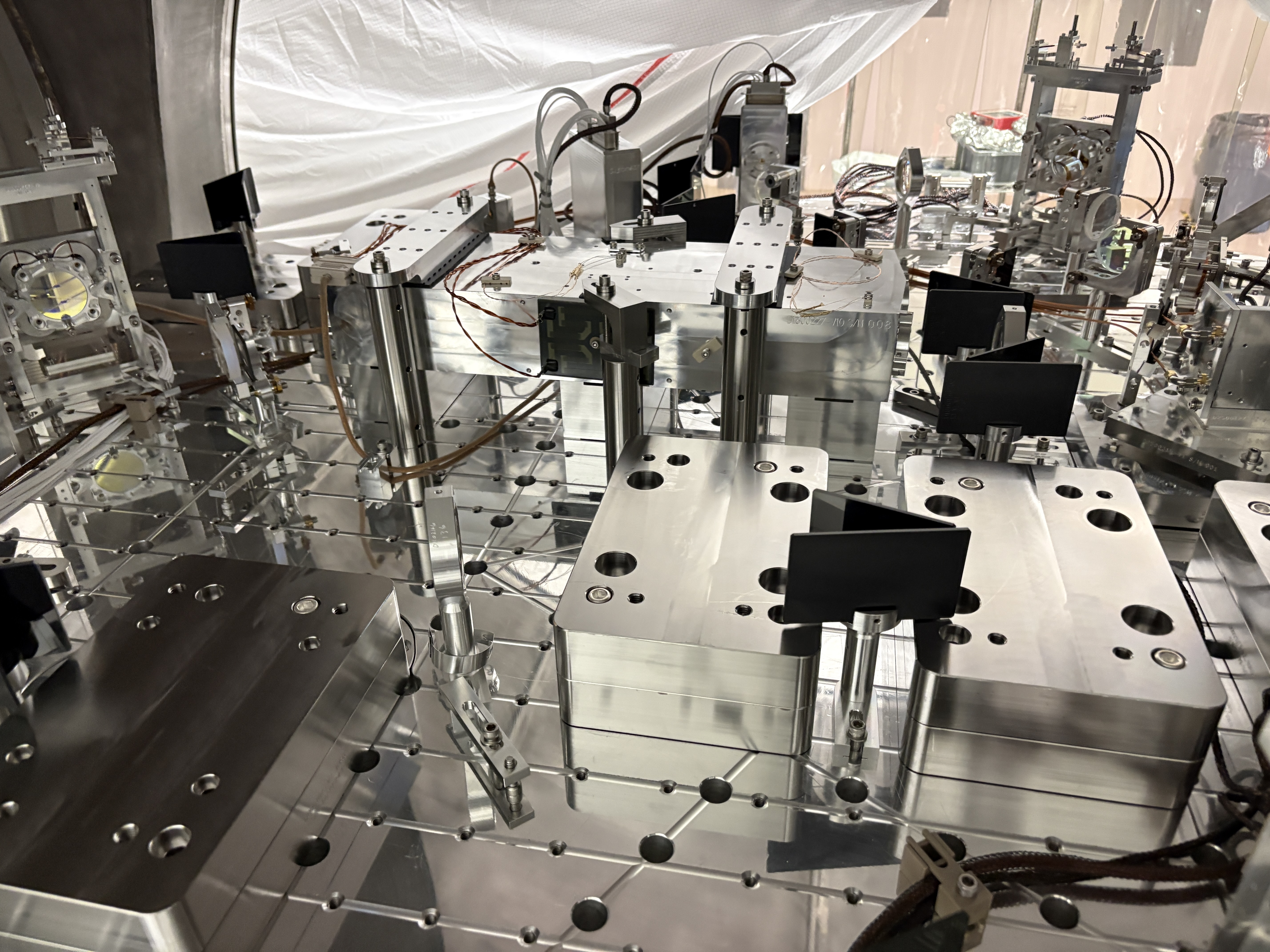
Tagging for EPO photos
Forgot to add some annotated pictures for beamdumps, so here they are.
The last one is from one of Betsy's pictures showing the beam dump for JAC L3 and JAC L2 reflection as well as JM1 transmission.


We installed JM1, balanced it and aligned it. A beam dump was placed behind it though we could not see the transmission with 1W input.
After this, JAC locked with RF without any problem though the input was wobbly when the purge was up.
We searched for unexpected ghost beams (also with 1W input) and didn't find any.
We uninstalled many (but not all) temporary dog clamps and irises.
We revisited the IMC alignment because it's been off in PIT since Thursday or Friday. We locked JAC using dither (because we wanted to turn down the purge air). We enabled the IMC WFS just for MC optics and steered JM3, but weren't able to center the MC2 trans. Steering JM3 just made the IMC transmission worse while making not much impact on the desired degree of freedon (JM3 PIT -> MC2 trans YAW, JAM3 YAW -> MC2 trans PIT).
Tomorrow, we'll revisit the IMC alignment. We'll also measure the power coming into JAC TRANS PD as well as the actual transmission of JAC while locking it with RF so we can use JAC trans PD as the measure of the power into HAM1.
FYI, there are about 24 beam dumps now installed on this table.
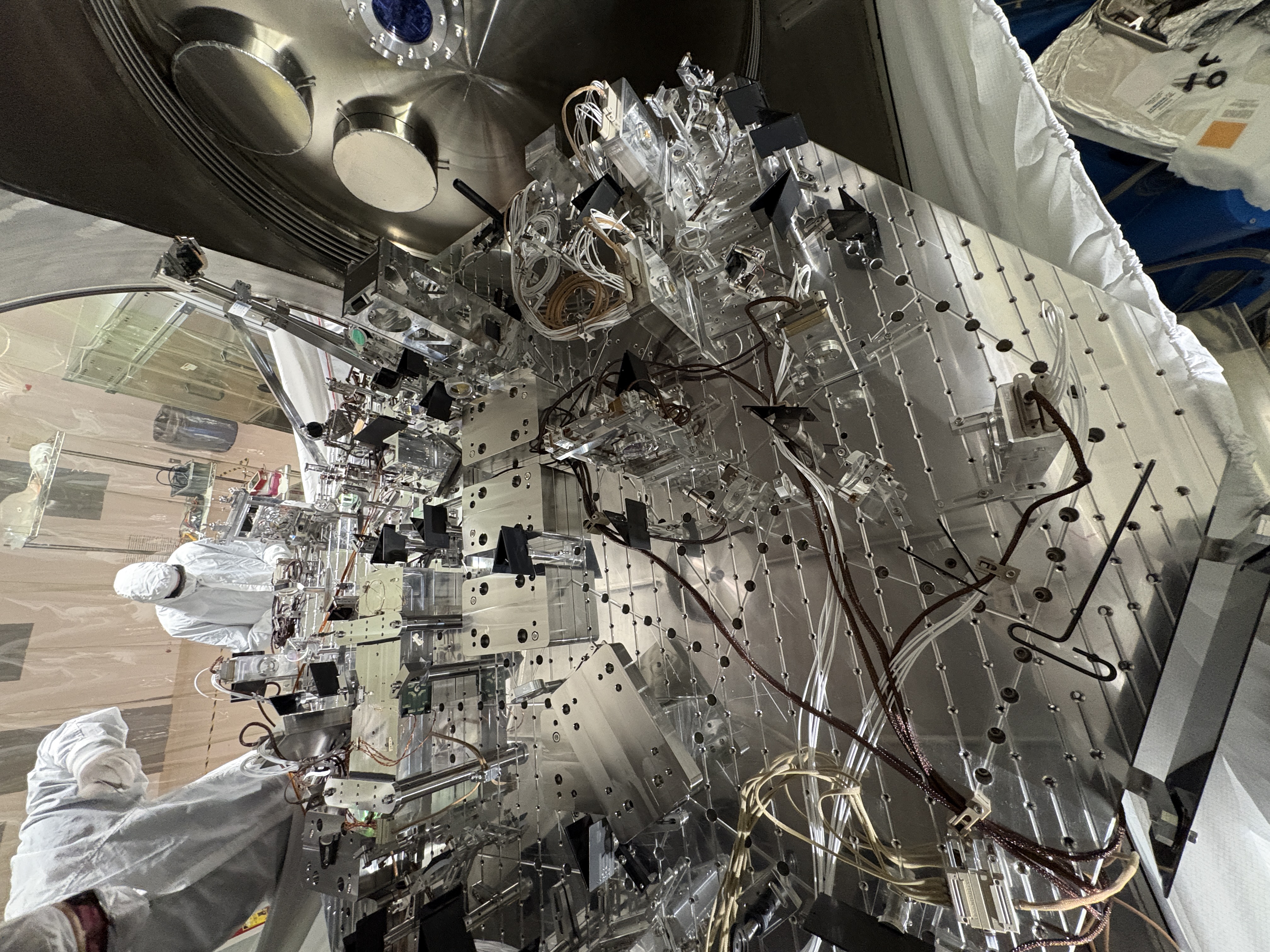
Tagging for EPO photos
One of the beam dumps on the picture was most likely NOT in its final place.
See my annotated version, the BD circled in orange is probably JM1 trans beam dump and relocated to the final location after this picture was shot.
In Feb/26 alog, this picture of Betsy's doesn't show the mystery dump and instead shows the JM1 trans beam dump in its final location, I think.

Ryan(s)
We added at +90 degree phase shift to the AS_B RF45 WFS to make the MICH loop work during PRMI ASC; screenshot attached of new values accepted in SDF. However, in testing this, the PRMI buildups didn't really improve, so it's possible more adjustments are needed here, which Ryan will check this evening.