Kevin, Sheila, Evan, Vicky
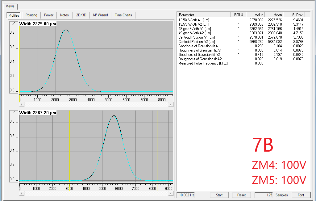
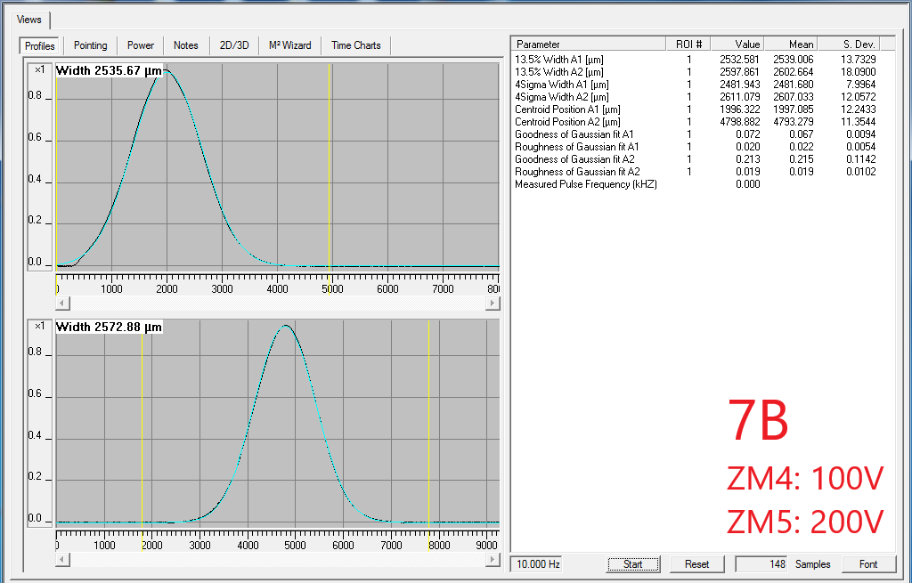
Summary: SQZ-OMC mode scans with hot OM2, and PSAMS 120/120 vs. 200/200. From this data, we should get single-bounce SQZ-OMC mode-matching with hot OM2, check SQZ readout losses (AS port throughput), and measure OMC losses via cavity visibility when locked/unlocked to the squeezer beam. With hot OM2, in sqz single bounce, SQZ-OMC mode-matching looks a bit better with PSAMS 120/120 than 200/200.
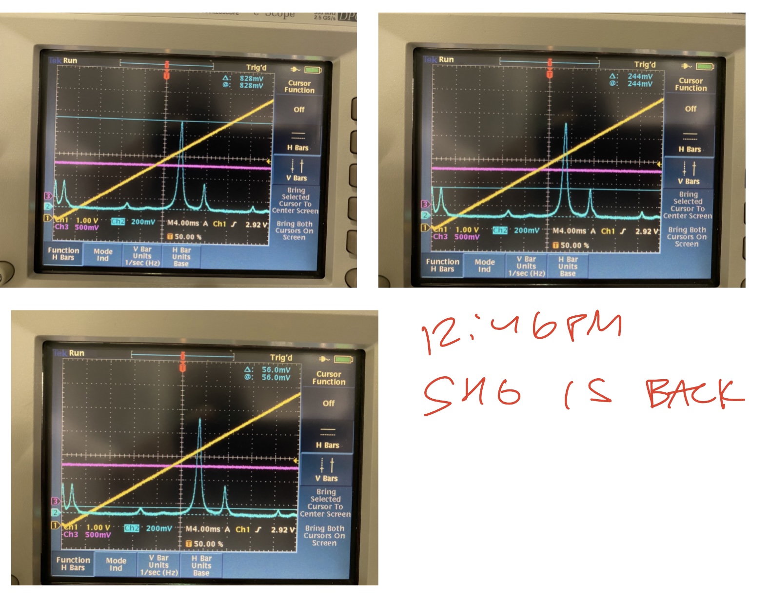
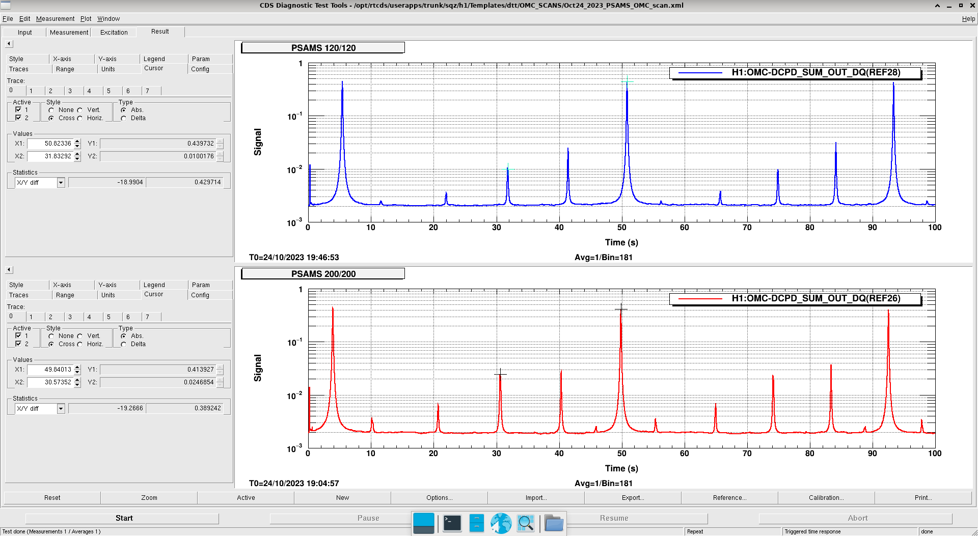
We'll ask Jennie W. to help us fit these SQZ-OMC mode scans. She can fit the double-peak in the 2xHOM, to give an accurate measure of SQZ-OMC mode-matching with hot OM2 and these two PSAMS settings. Here is just naively calculating mismatch from the relative power in TEM20 (TEM20/(TEM00 + TEM10/01 + TEM20)), and then calculating the total power not in TEM00 (ie 1-TEM00/(TEM00 + TEM10/01 + TEM20)), to get the following estimates on SQZ-OMC mode matching:
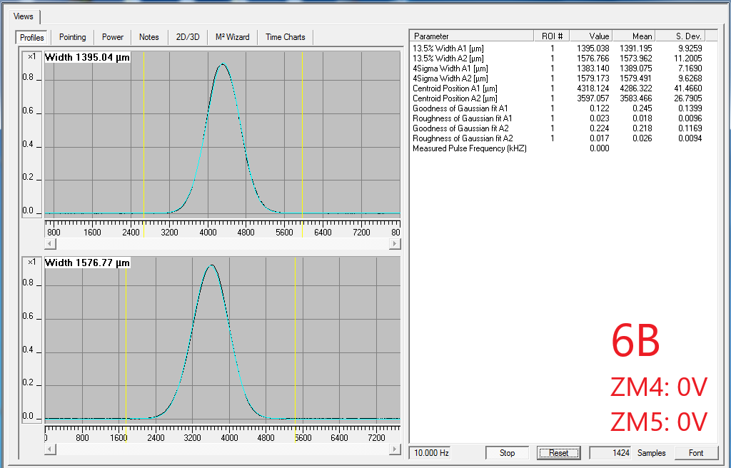
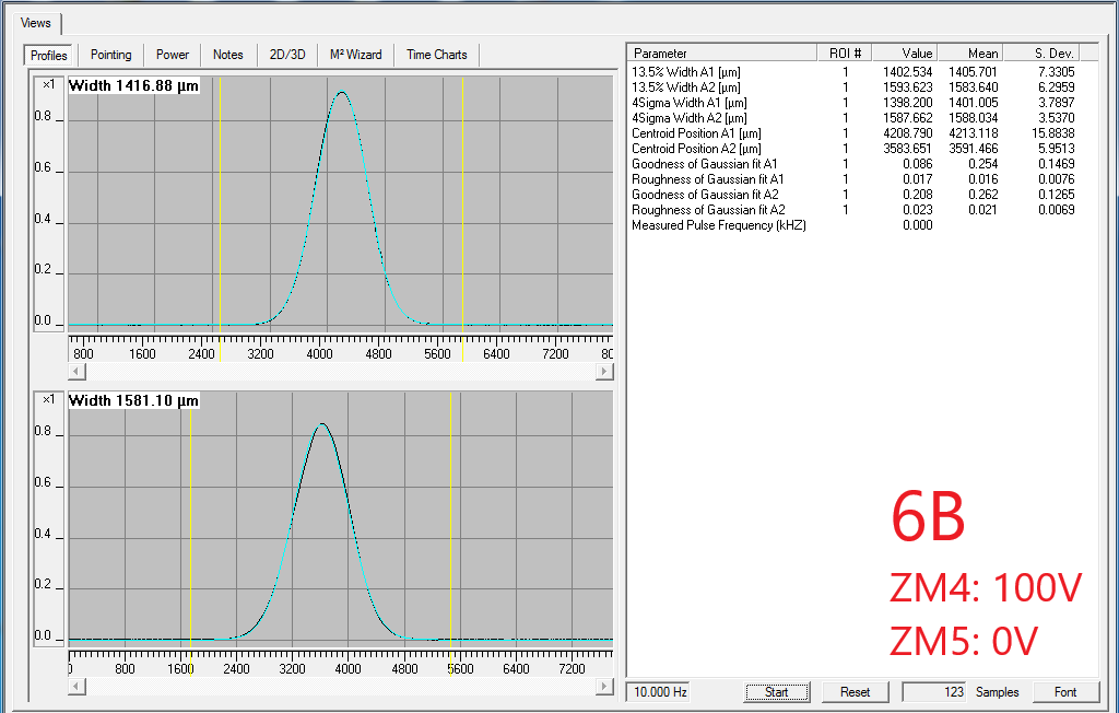
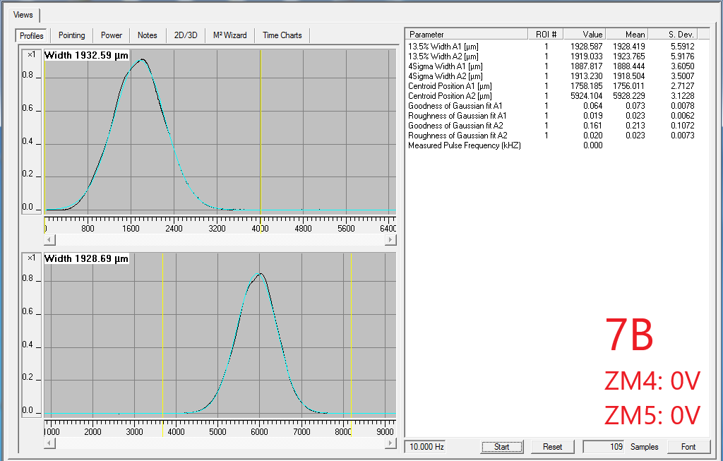
PSAMS 120/120, scan: 10/24/23 19:46:53 UTC + 200 seconds.
--> mismatch ~ TEM20/peak_sums ~ 2%. Total incl. mismatch + misalignment: 1-tem00/peak_sums ~ 8%.
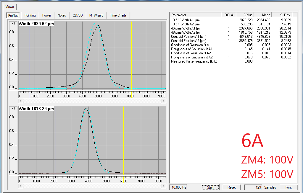
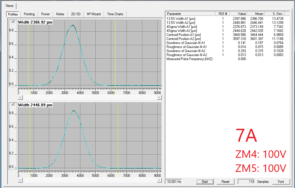
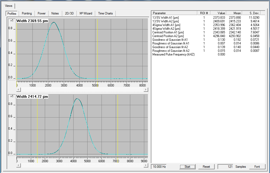
PSAMS 200/200, scan: 10/24/23 19:04:57 UTC + 200 seconds.
--> mismatch ~ TEM20/peak_sums ~ 5%. Total incl. mismatch + misalignment: 1-tem00/peak_sums ~ 12%.
We will follow-up with analysis on OMC loss measurements based on cavity visibility, more accurate SQZ-OMC mode mismatches from these scans, and checking single-bounce SQZ powers through the AS port.
---------------------------------------------------------------------------
Notes:
- To begin SQZ-OMC mode scan, if SQZ-IFO is aligned -- with SRM aligned, SR2 + SR3 misaligned, Open sqz beam diverter, open fast shutter.
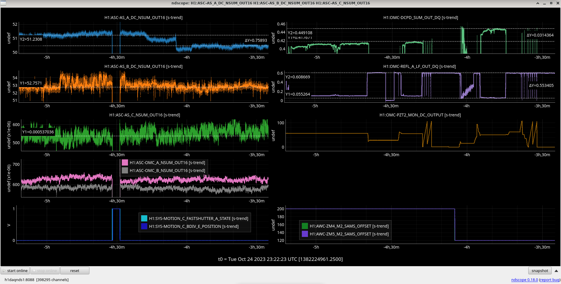
- We started aligning with the PSL beam before we realized we forgot to open the fast shutter. For reference with this working, 10W PSL gave about ASC_AS_{B,C}_DC_NSUM_OUT16 ~ 2000, ASC-AS_C_NSUM_OUT16~0.023, ASC-OMC_{A,B}_NSUM_OUT_DQ~0.023.
- With 75mW seed power into SQZT0 seed fiber, and opo at LOCKED_SEED_DITHER:
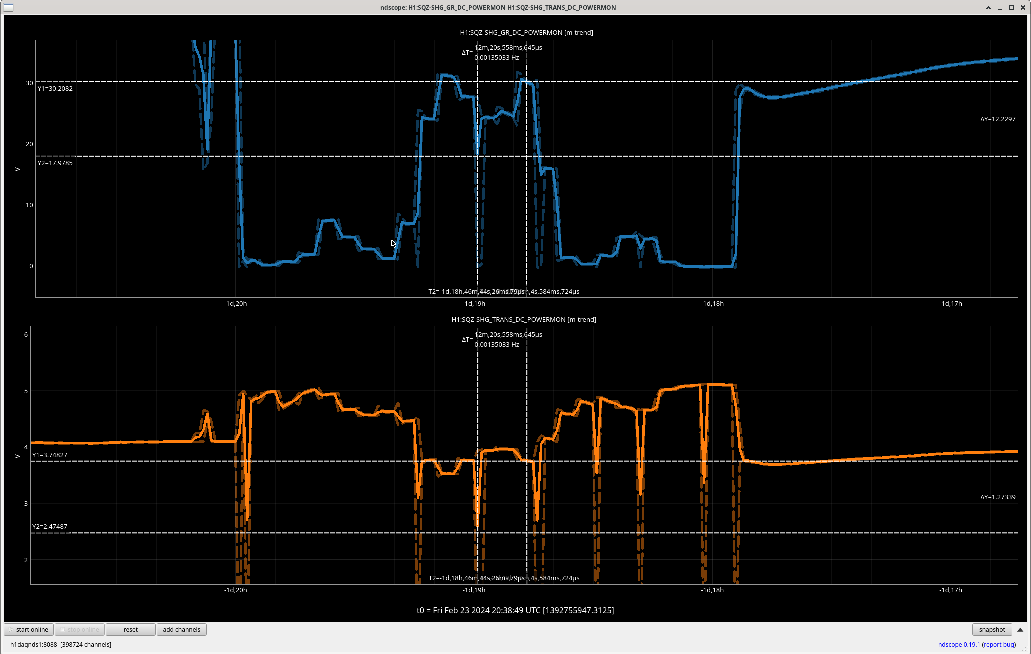
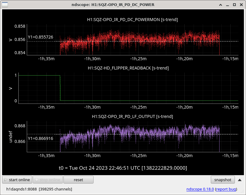
- At the end, we measured the opo ir transmitted powers on sqzt7: OPO_IR_PD_LF_OUTPUT = 0.867mW, and OPO_IR_PD_DC_POWERMON = 0.856mW. This PD calibration was checked recently LHO:72761, Sept 2023.
- 51 counts on ASC-AS_{A/B}_DC_NSUM_OUT16, 520e-6 counts on ASC-AS_C_NSUM_OUT16.
- Then engaging DC3/4 centering loops worked.
- Then OMC QPD ASC set master gain to 0.02 (one click up), this aligned OM3 + OMC SUS.
- Lock OMC on SQZ seed beam as carrier. Sheila manually walked through relevant OMC_LOCK guardian steps, including manual scan of OMC PZT2 volts to find sqz tem00 carrier.
- Set trigger to 0 or 0.1 for OMC to lock on SQZ seed beam as the carrier
- Turn on OMC QPD ASC servo to align OM3+OMC SUS to sqz beam. Master gain = 0.02 (one click up). With OMC QPD ASC, this brought DC sum = 0.4 now, which from DTT was the TEM00 peak height.
- OMC scan here before walking OMC QPD alignment, PSAMS 200/200. DTT Refs 24 (dcpd sum), 25 (omc pzt).
- Manually optimize OM3/OMC alignment with OMC locked on SQZ beam. This was after using & converging OMC QPD servos, then turning them off. Mostly walking yaw between OM3/OMC, then slightly in pitch. This manual walking improved OMC DCPD SUM transmission from 0.405 to 0.411 (~1.5% improvement).
- We can compare OMC visibility with OMC locked/unlocked from the SQZ beam. Follow up: calculate OMC losses from OMC-SQZ locked/unlocked visibility.
- Locked GPS times, PSAMS 200/200: 1382207658 - 1382208152
- Unlocked OMC: Turned off integrator, boost, trigger, then moved PZT offset to off-resonance.
- Unlocked GPS times: 1382208285 - 1382208585
- Dark noise: Turned off DC centering, fast shutter, sqz beam diverter.
- Dark GPS times: 1382208720 - 1382208813
- Then re-opened sqz beam diverter, opened fast shutter, DC centering loops DC3 + DC4 engaged, OMC QPD ASC master gain set to 0.02, converge OMC QPD ASC then freeze it, then scan OMC-PZT2_OFFSET (green slider). Use PZT2 offset scan to manually find SQZ TEM00 carrier. Turn ON OMC-LSC servo input, integrator, boost. Manually re-align OM3 + OMC SUS to optimize OMC-DCPD_SUM_OUT transmission. Again it was mostly yaw on OM3+OMC, then slightly pitch; manual walking improved alignment slightly (few %) again.
- PSAMS 200/200 data, with re-optimized alignment:
- Locked GPS times, PSAMS 200/200: 1382209341 - 1382209482
- OMC Scan, PSAMS 200/200. DTT Refs 26 (dcpd sum), 27 (omc pzt). Gpstime: 10/24/23 19:04:57 UTC, 100 second ramp.
- Unlocked GPS times: 1382210147 - 1382210207
- Changed ZM4/5 PSAMS to 120/120, left DC3/4 centering ON. Re-lock OMC on seed beam (without touching OMC QPD ASC since we previously aligned/optimized it). With OMC-SQZ locked again and same OM3+OMC alignments as before, alignment with psams120/120 is not good. Some alignment confusion with OMC-LSC servo bank saturating. We turned back on OMC QPD ASC master gain 0.02 since we were kinda far off in the alignment. Here with hot OM2, the OMC transmission looks higher with PSAMS 120/120 than with PSAMS 200/200.
- PSAMS 120/120 data, with re-optimized alignment:
- Locked GPS times, PSAMS 120/120: 1382211311 - 1382211449
- Unlocked GPS times: 1382211637 - 1382211755
- OMC Scan, PSAMS 120/120. DTT Refs 28 (dcpd sum), 29 (omc pzt). Gpstime: 10/24/23 19:46:53 UTC, 100 second ramp.
---------------------------------------------------------------------------
Some relevant alogs, as we try to piece together the SQZ-IFO, IFO-OMC, and SQZ-OMC mode matchings:
- Cold OM2, single bounce SQZ-OMC mode scans, alignment less controlled than this time: Jan 2023, LHO:66946.
- Cold OM2, single bounce, PSAMS 200/200 ~ better SQZ-OMC mode-matching.
- SQZ-IFO full-lock frequency-dependent mode matching: LHO:73400 first pass, then LHO:73621 repeat with ASC frozen.
- Hot OM2, full lock, PSAMS 200/200 ~ better SQZ-IFO(-OMC?) mode-matching. DARM SQZ noticeably flatter in this configuration.
- 200/200 better also suggested by ADF transmission + more anti-squeezing.
- Hot OM2, single bounce SQZ-OMC mode scans (this alog):
- Hot OM2, single bounce, PSAMS 120/120 ~ better SQZ-OMC mode-matching.