corey.gray@LIGO.ORG - posted 12:59, Monday 22 January 2024 (75496)
Mon DAY Ops Summary
TITLE: 01/22 Day Shift: 16:00-00:00 UTC (08:00-16:00 PST), all times posted in UTC
STATE of H1: Planned Engineering
INCOMING OPERATOR: None
SHIFT SUMMARY:
Big Tasks Of The Day: (1) HAM7 doors taken off, (2) HAM7 work begins, & (3) Laser Hazard in LVEA / EX is back to SAFE
LOG:
- Alarm Handler:
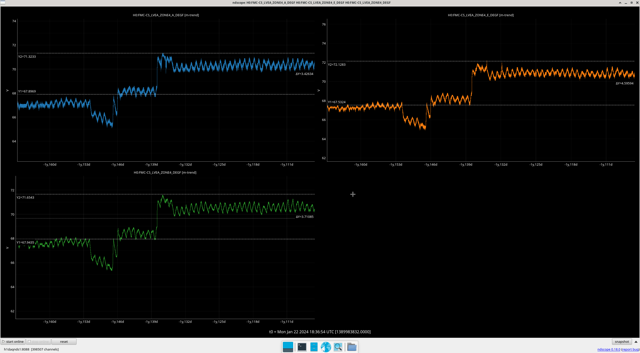
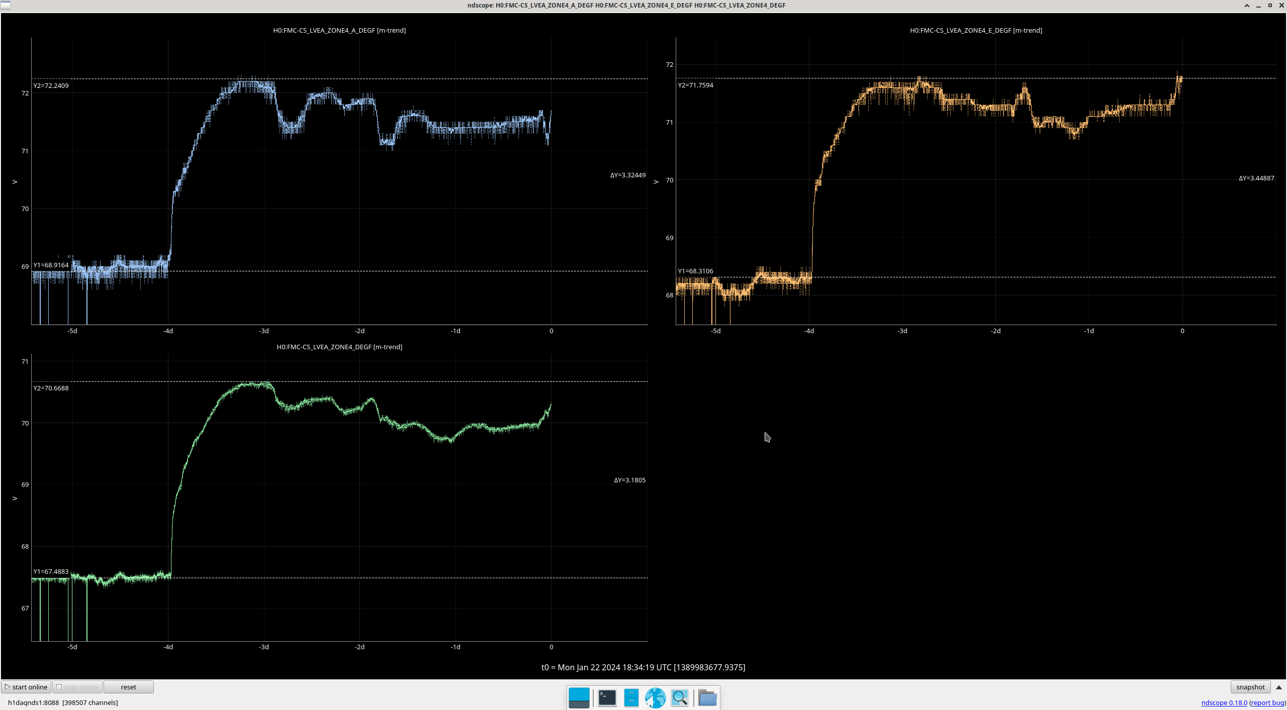
- 1643 Zone 2A temperature
- 1520 Furniture moving work (randy)
- 1617-1956 Technical cleaning around HAM7 (LVEA) (karen & kim)
- 1632-1933 HAM7 doors morning (jordan, gerardo)
- 1632jordan, 1652gerardo,
- HAM7 ISI tripped
- 1638 FARO system surveying (jason, ryanC)
- 1646 Cable search around CER & HAM6 for HAM7 alignment later (fil)
- 1652 Turning down purge air on output arm (gerardo)
- 1655 Prep & tool search in optics lab (camilla)
- 1700-1858 HAM6 SUS TFs (rahul)
- 1706-1715 LVEA & FARO team checks (tyler)
- 1721 Sealing up PCal & transitioning EX to laser SAFE (tony)
- 1755 EX laser SAFE!
- 1735 SEI_ENV node work (tj)
- 1738-1741 Dropping off Contamination Control kit at HAM6/7 (mitch)
- 1754-1801 West Bay trip to grab tools for EX (mitch)
- 1759 Betsy beginning her in/out of LVEA for vent activities
- 1759 Taking Eric O to check out H7 door work.
- 1801-1843 Dropping off EX kits for EX flange baffle work later (mitch)
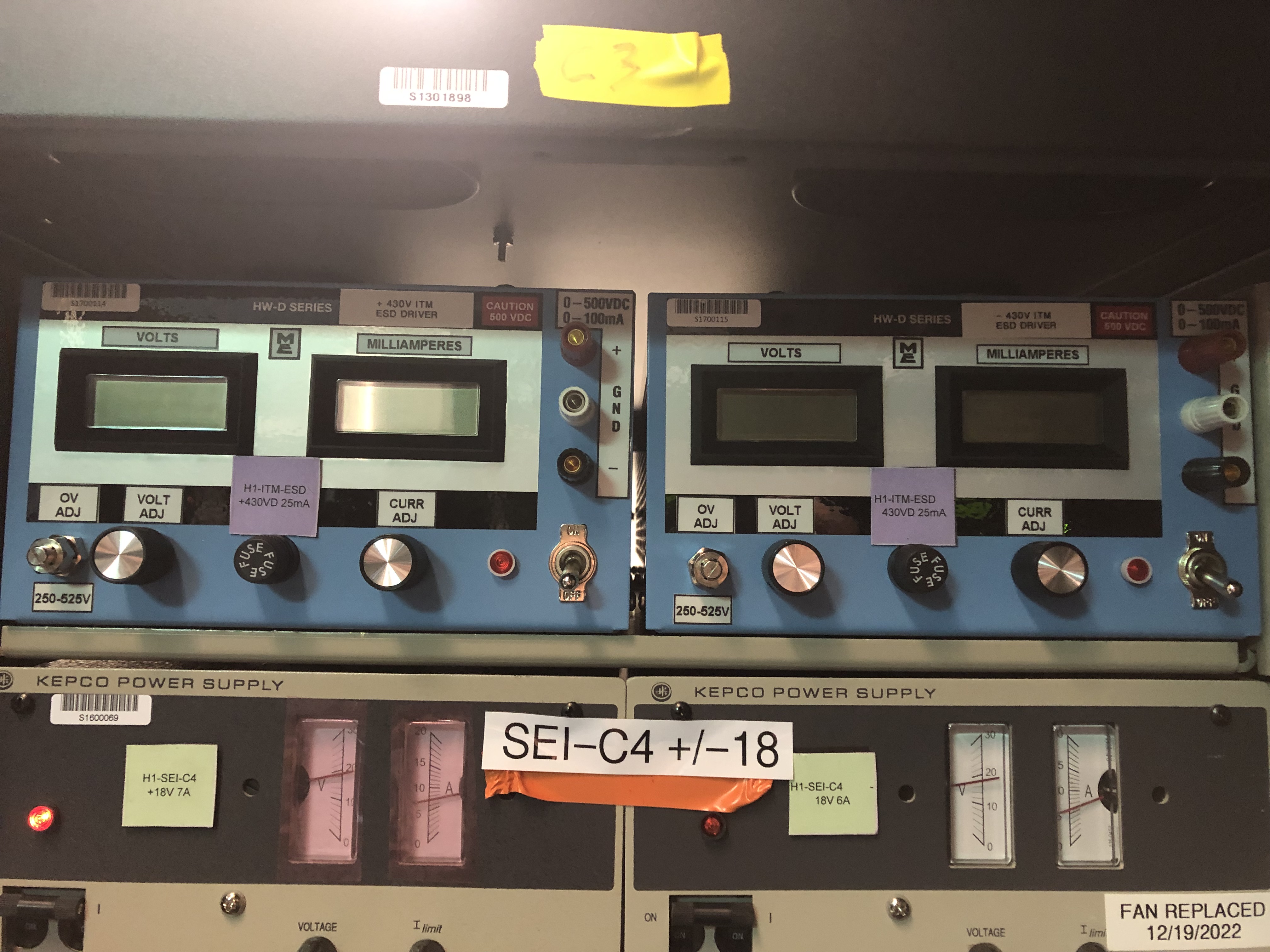
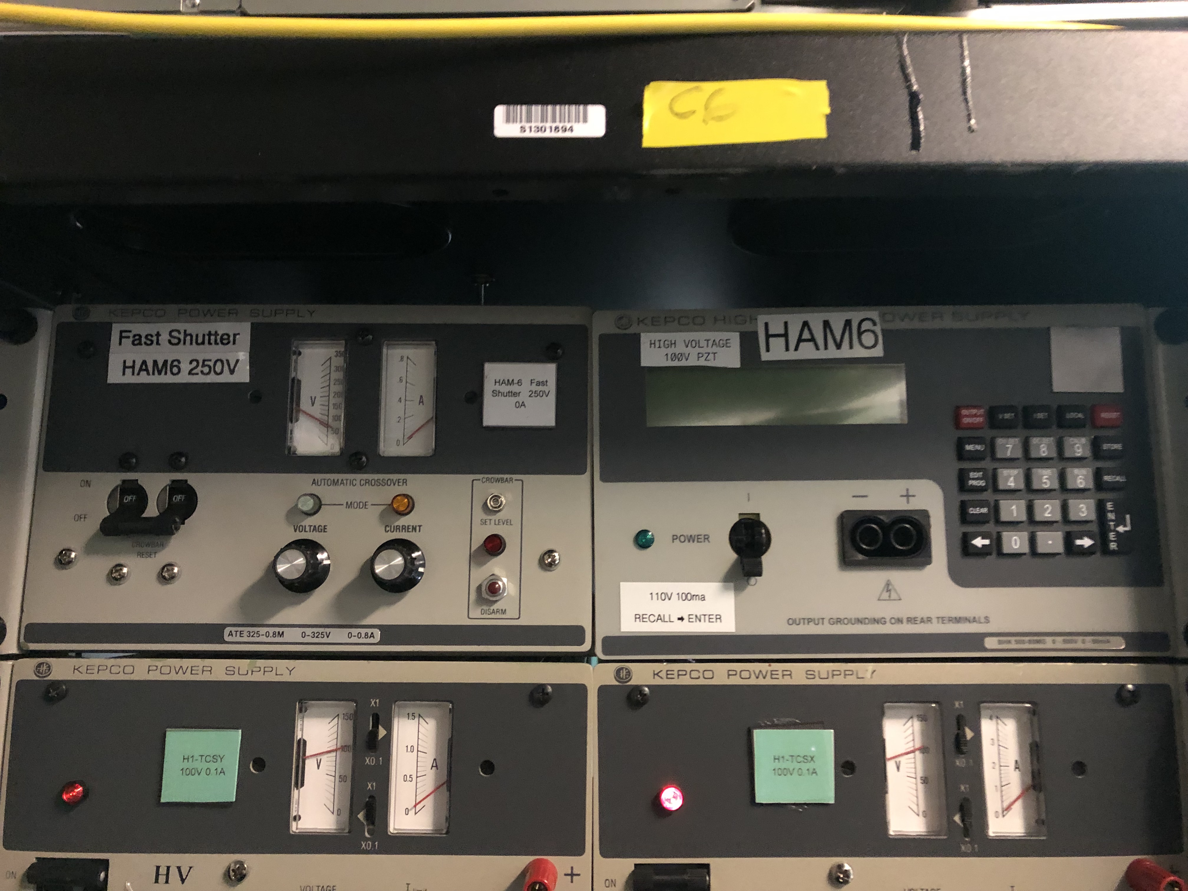
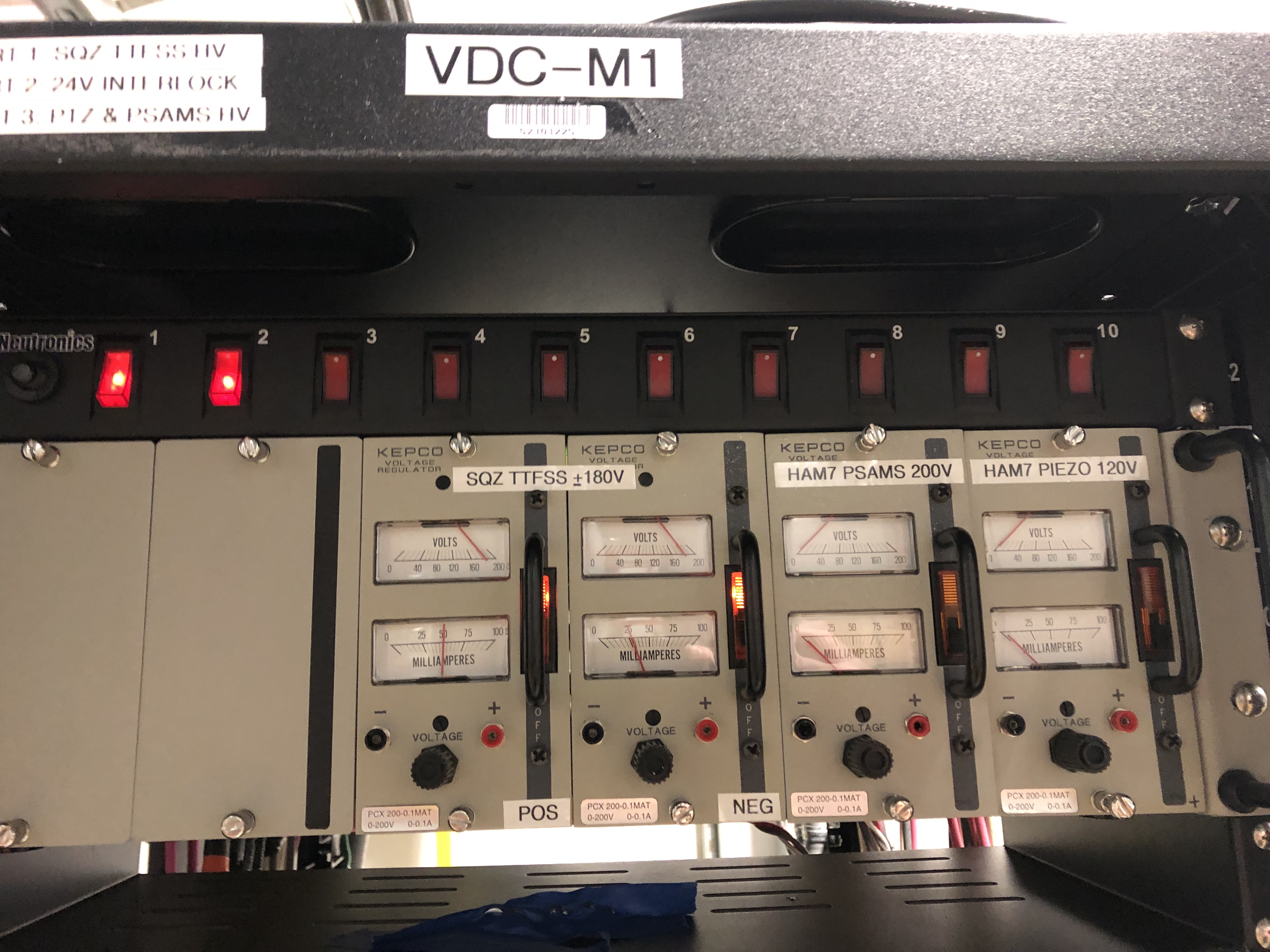
- 1805 Ramped down the PZTs (or was it a P-SAMS thing?) to zero in prep for High Voltage being turned ON (sheila)
- 1825 Incoming 7.0EQ from Kyrgyzstan area.
- 1840 Locking HAM7 ISI (jim)
- 1847 High voltage (pzt/P-SAMS) turned ON (fil)
- HAM6 SQZ work
- 1856 Prep/staging for HAM6 OMC work (koji)
- 1935 Prep/staging for HAM6 OMC (rahul)
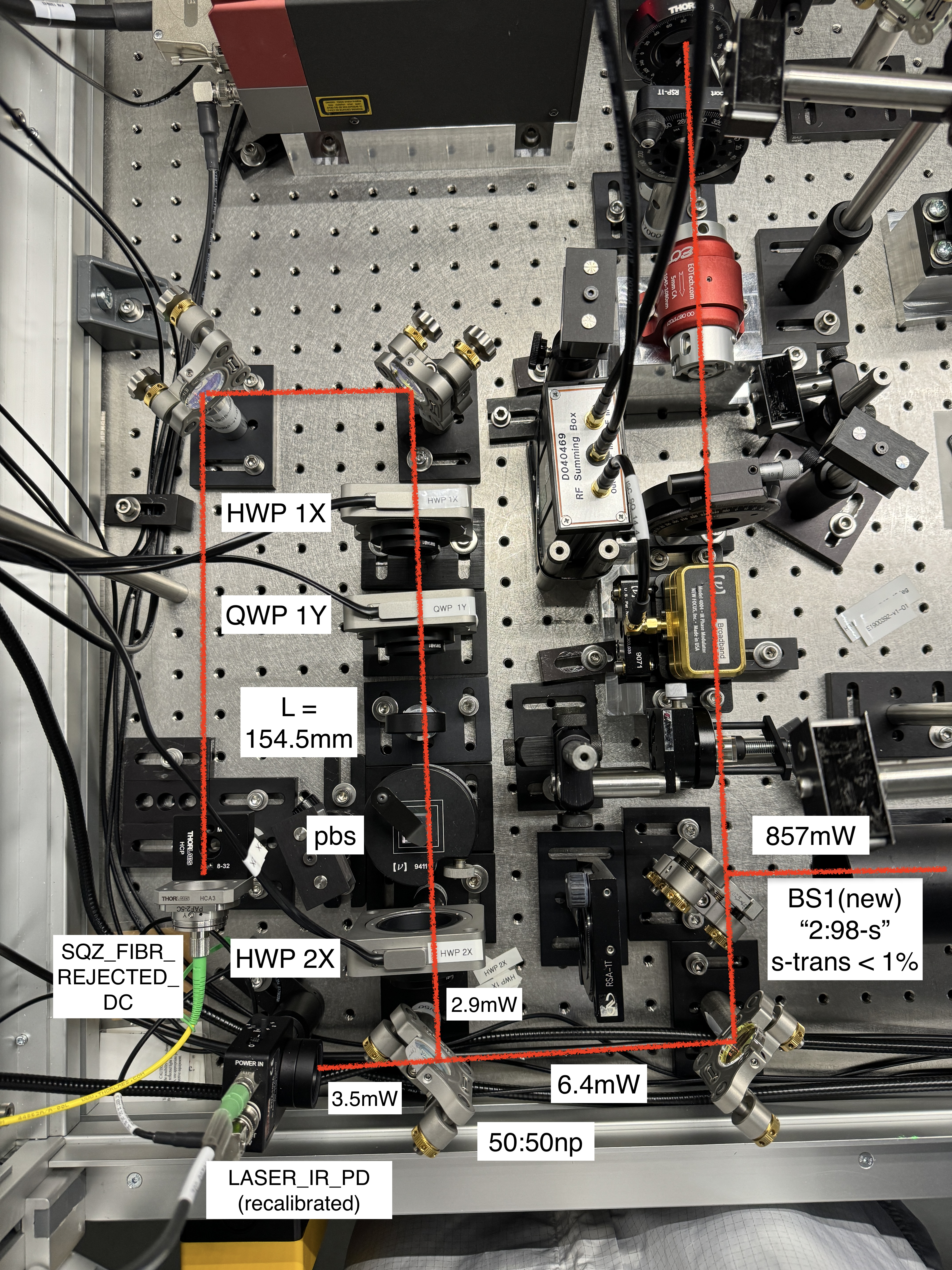
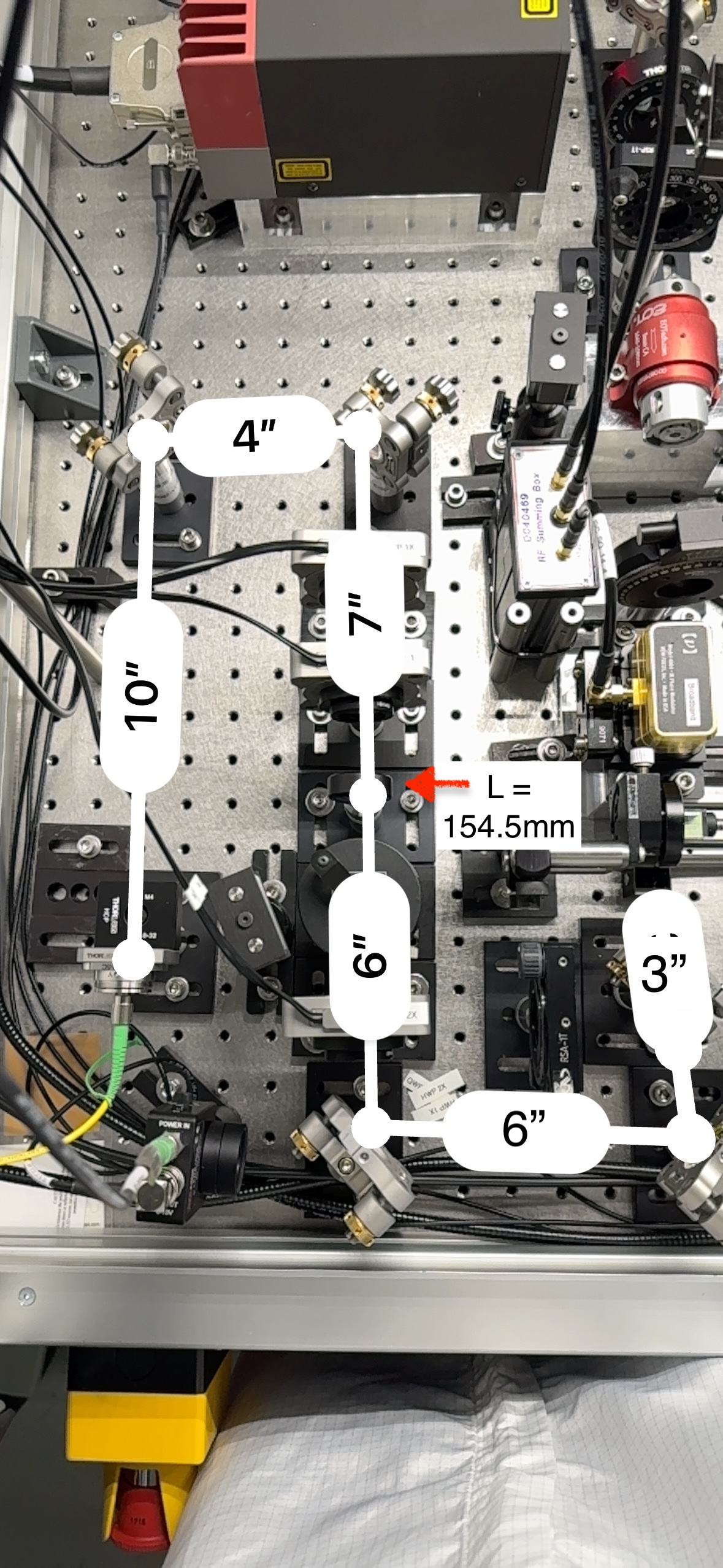
- HAM7 SQZ work
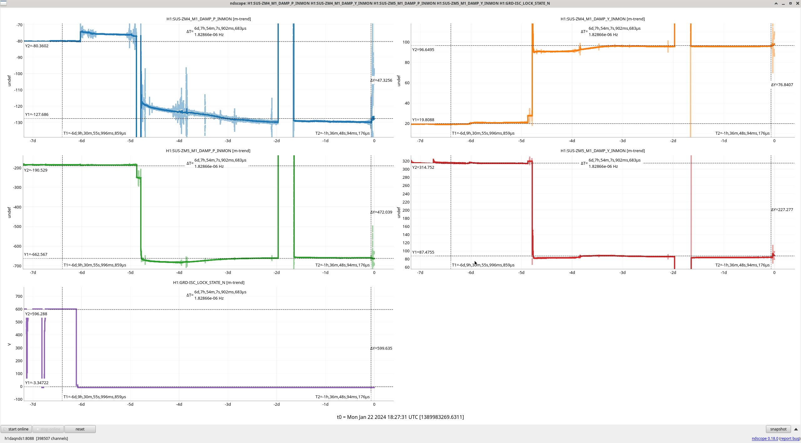
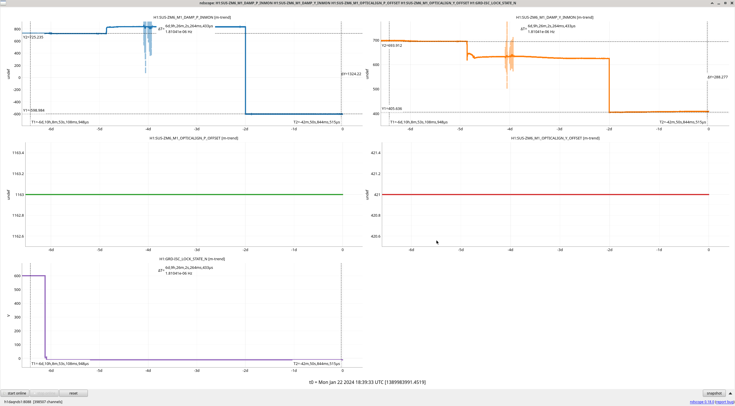
- 1943 Moving ZMs around (austin)
- HAM7 team beginning in-chamber work (sheila, julian, naoki, vicky, camilla)
- Tried to find a Humidity sensor for in-chamber work....found some in Richard's office, Betsy grabbed them, and Betsy running a RH sensor out to the HAM7 team.
- 1906 Quick visit in the PCal lab (tony)
- 1932 Prep for Transitioning LVEA to Laser SAFE!!! (Camilla)
- 2057 Running equipment down for Wind Fence at EY (randy)
- (Handed off my shift to TJ at 1pm PST)