Rana, Evan
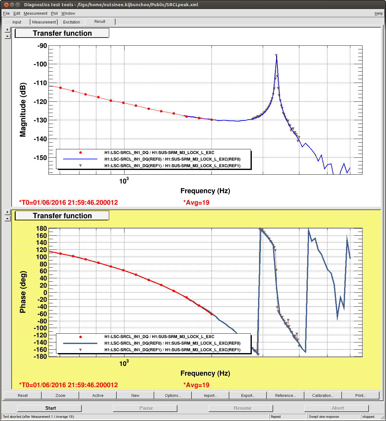
WE measured the SRM to SRCL TF today to find the frequency and Q of the internal mode. Our hypothesis is that the thermal noise from the PEEK screws used to clamp the mirror into the mirror holder might be significant contribution to DARM.
The attached Bode plot shows the TF. The resonance frequency is ~3340 and the Q ~150. Our paper and pencil estimate is that this may be within an order of magnitude of DARM, depending upon the shape of the thermal noise spectrum. If its steeper than structural damping it could be very close.
"But isn't this ruled out by the DARM offset / noise test ?", you might be thinking. No! Since the SRCL->DARM coupling is a superposition of radiation pressure (1/f^2) and the 'HOM' flat coupling, there is a broad notch in the SRCL->DARM TF at ~80 Hz. So, we need to redo this test at ~50 Hz to see if the changing SRCL coupling shows up there.
Also recall that the SRCLFF is not doing the right thing for SRM displacement noise; it is designed to subtract SRC sensing noise. Stay tuned for an updated noise budget with SRM thermal noise added.
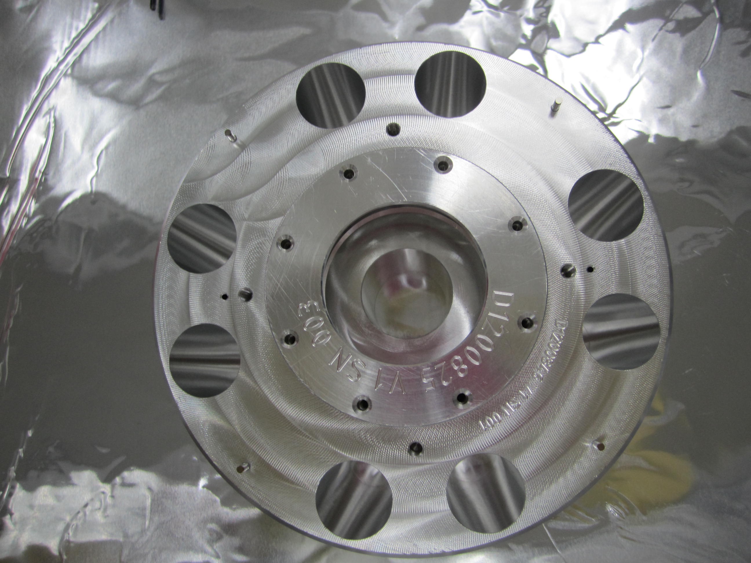
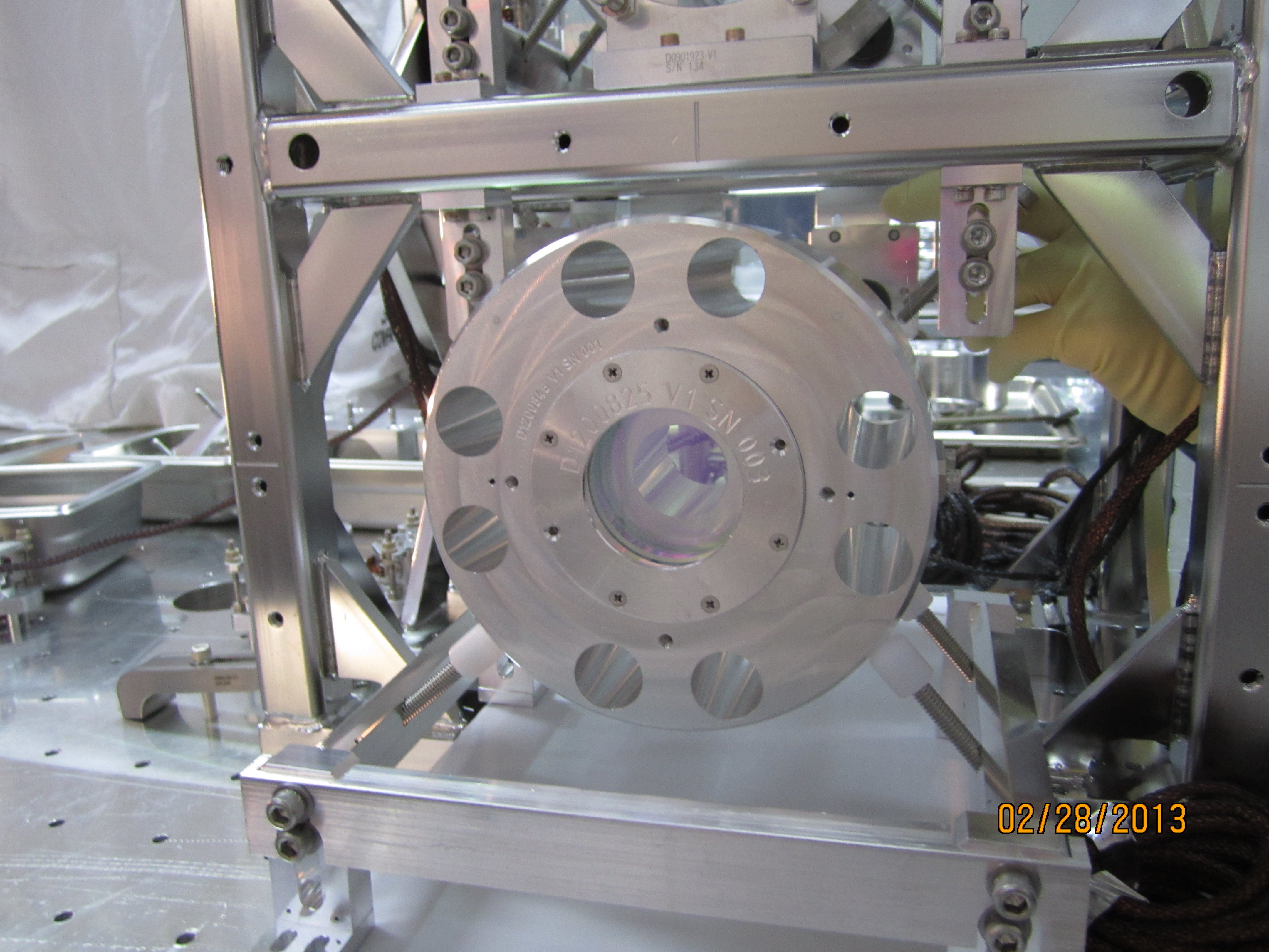
** see https://alog.ligo-wa.caltech.edu/aLOG/index.php?callRep=27455 for pictures of the SRM compsoite mass.
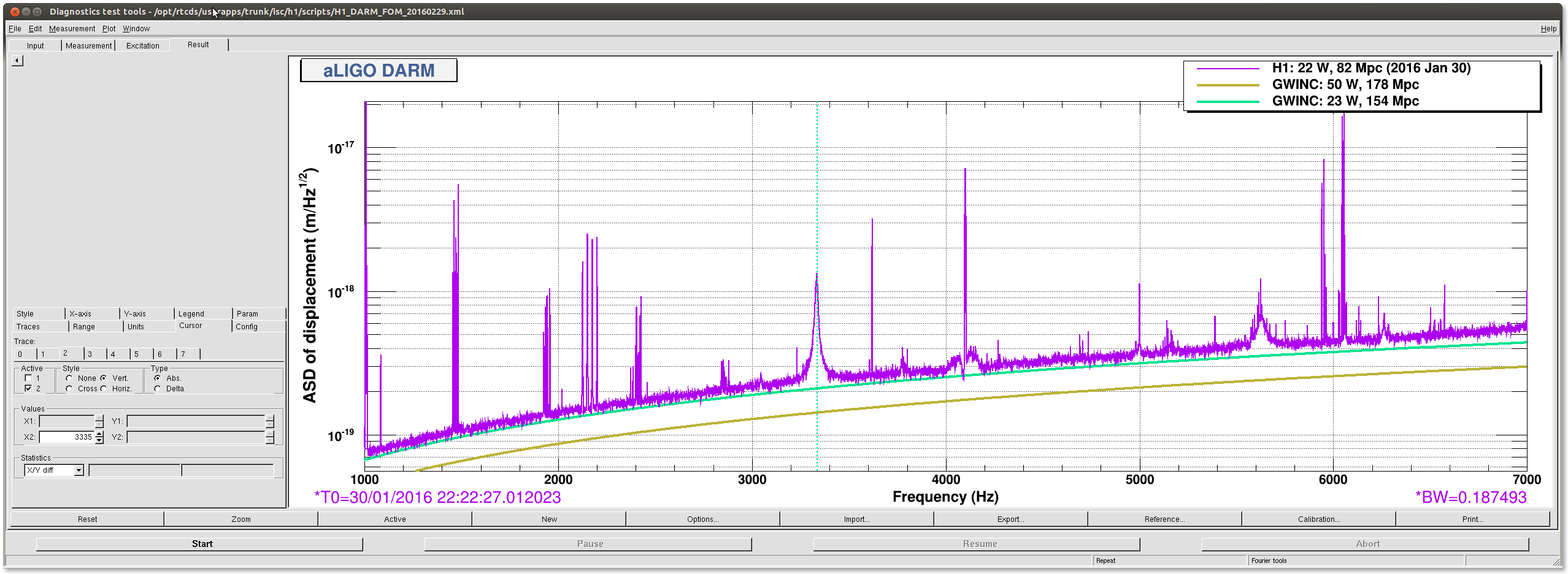
The peak is also visible in the DARM spectrum. In this plot the peak is at 3335 instead of 3340 Hz. Why is there a 1.5% frequency shift?
Here are projected SRM thermal noise curves for structural and viscous damping.
Given a typical SRC coupling into DARM of 1×10⁻⁴ m/m at 40 Hz, 20 W of PSL power, and 13 pm of DARM offset (25019), this would imply a noise in DARM of 1×10⁻²⁰ m/Hz1/2 at 40 Hz if the damping is structural.

When I modelled the optics in https://dcc.ligo.org/LIGO-T1500376 and in particular the surrogate SRM I had assumed optic was bonded. After looking again earlier with Rana and Betsy realised it is held with 2 set screws (Peek?) on barrell at 12 o'clock and two line contacts at 4 and 8 o'clcok. See https://dcc.ligo.org/LIGO-D1200886.
The previous bonded model for the SRM surrogate (I believe) had a fisrt mode predicted around 8k Hz. However, from a quick model I ran today (with the set screws etc ... ) the first mode appears to be around 3400 Hz. The mode is associated with the optic held with the peek screws. (Now I was doing model using remote desktop so I will need to check it again when I get a better connection, so more to follow on this. I will also post updated model, once I get back to Caltech.)
The ~3340Hz peak is also clearly visible in the PDA/PDB x-correlation spectrum. See alog 26345.
A couple of comments on this topic:
- There is no feature at 3340 Hz in the L1 DARM spectrum, nor within several hundred Hz of this. So the main mode of the L1 composite SRM seems to be at a different frequency, though I think there has never been a transfer function measured there above ~1 kHz that would indicate the mode frequency (put on todo list). The first attached plot shows Kiwamu's full-O1 DARM and cross-correlation spectra for H1 and L1, zoomed in to the several kHz region. There are some peaks in L1 in the 4700-5100 Hz region, but it's fairly complicated in that region.
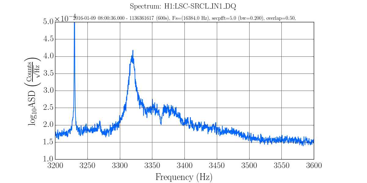
- The thermal noise peak in Evan's SRM plot is at a level of 2e-15 m/rtHz, which is a bit above the SRCL sensing shot noise level, so we should be able to see it in SRCL. The second attached plot shows a spectrum of the SRCL error signal from January 9, 2016. From the Aug 2015 entry 20270, the shot noise corresponds to a displacement noise of 1.3e-15 m/rtHz. In the attached spectrum, the mode peak (which is at 3320 Hz here - ?), is 2.5x above the shot noise level, putting it at about 3e-15 m/rtHz. This is a bit higher than in Evan's model, but it is actually remarkably close. (I didn't include it in this plot, but the DARM spectrum also shows this peak at 3320 Hz at this time, and there is 0.8 coherence with SRCL at the peak.)
Danny, Matt (Peter F remotely)
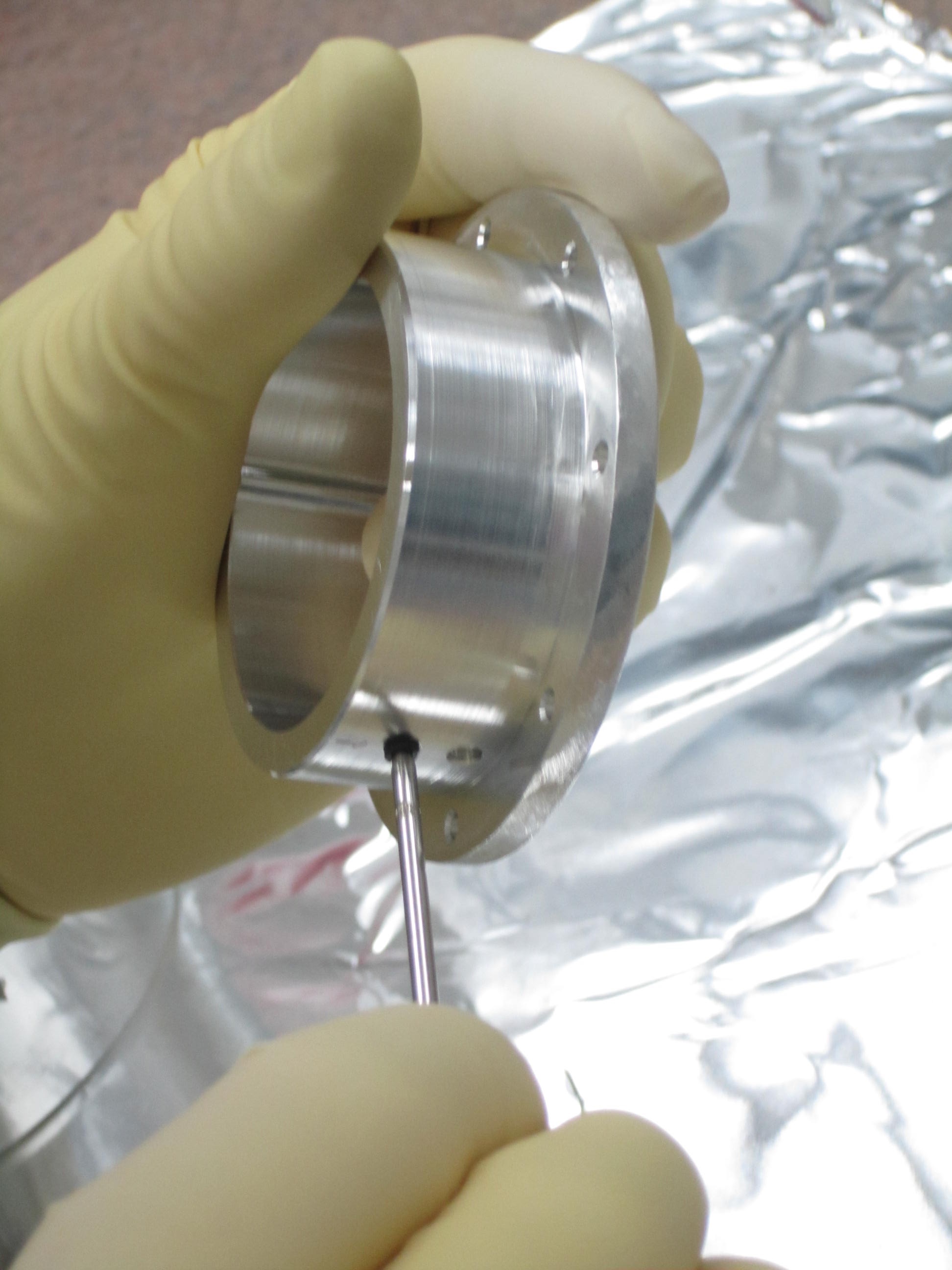
Due to the issues currently seen at LHO, we were asked how the LLO SRM surrogate was put together and if we could add to the alog for a record of the process. The easiest way is to do it via photos (which we have of the assembly process).
IMG_1462....There are only two setscrews that hold the optic in place. Can be seen putting these in place below in the "cup" that holds the optic (eventually). Im not sure of the material but Peter F's speculation is that "I think those set screws must be the carbon-loaded PEEK type. The only other option I can think of for a black set screw would be carbon-steel, and it surely isn’t that."
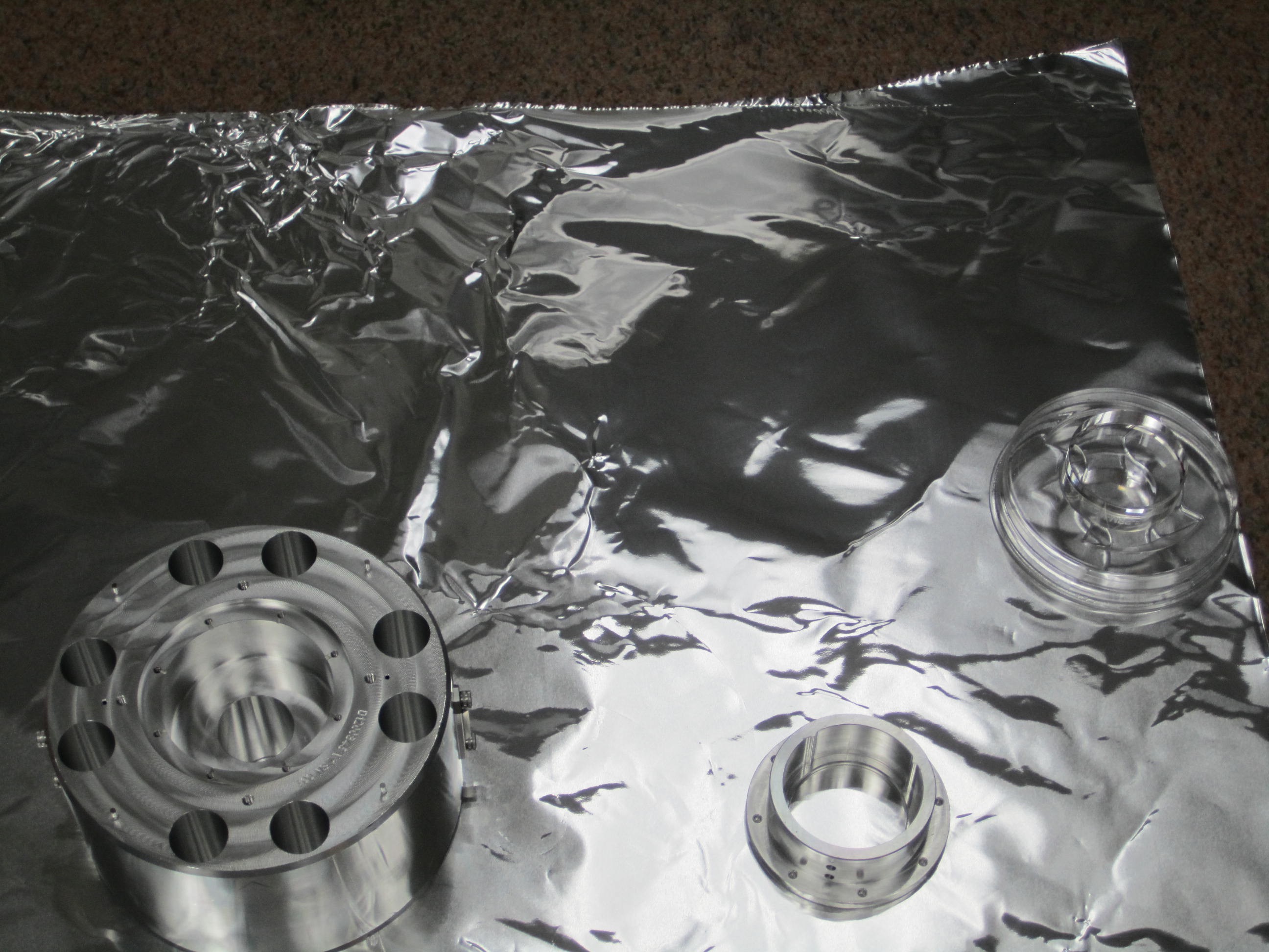
IMG_1455...Here you seen the three main parts. The optic, the “cup” that the optic goes into and then the main mass the cup goes in. Note in the “cup” you see the two raised parts at around 4 and 8 o’clock that the setscrews ‘push’ the optic onto. So its not 'really' a three point contact, its 2 points (set screws) and 2 lines (in the holder)
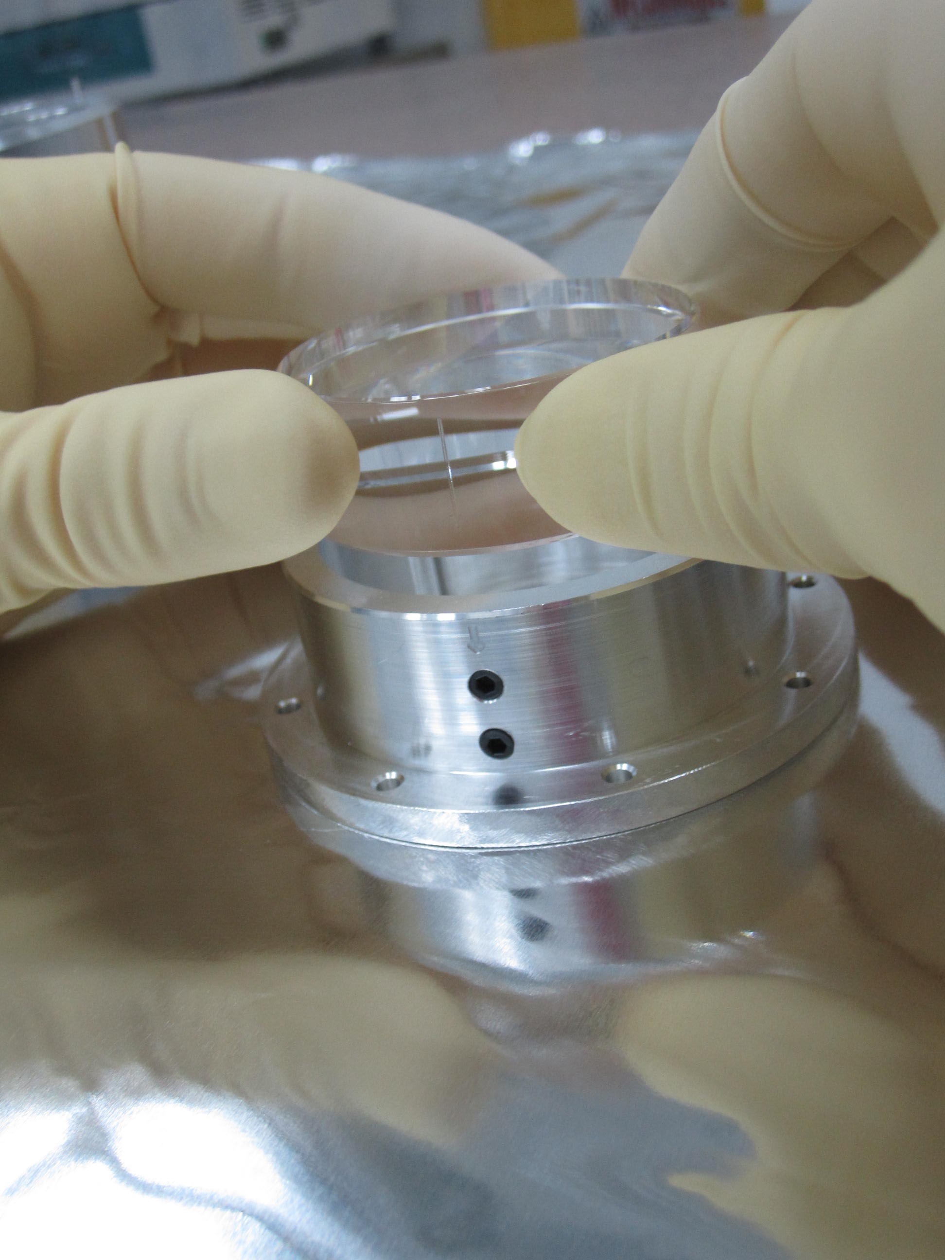
IMG_1466...Here is the optic going into the cup making sure the fiducial on the optic lines up with the arrow on the cup
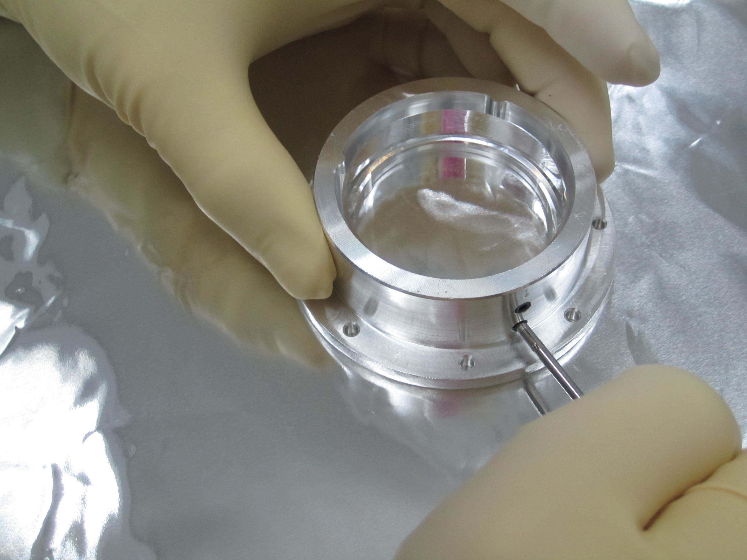
IMG_1470.....Optic now in the cup and doing up the setscrews that hold it in place. I cant remember how much we torqued it up (we only did it by hand). But as Peter F again speculated that perhaps we just did the setscrews up tighter than LHO
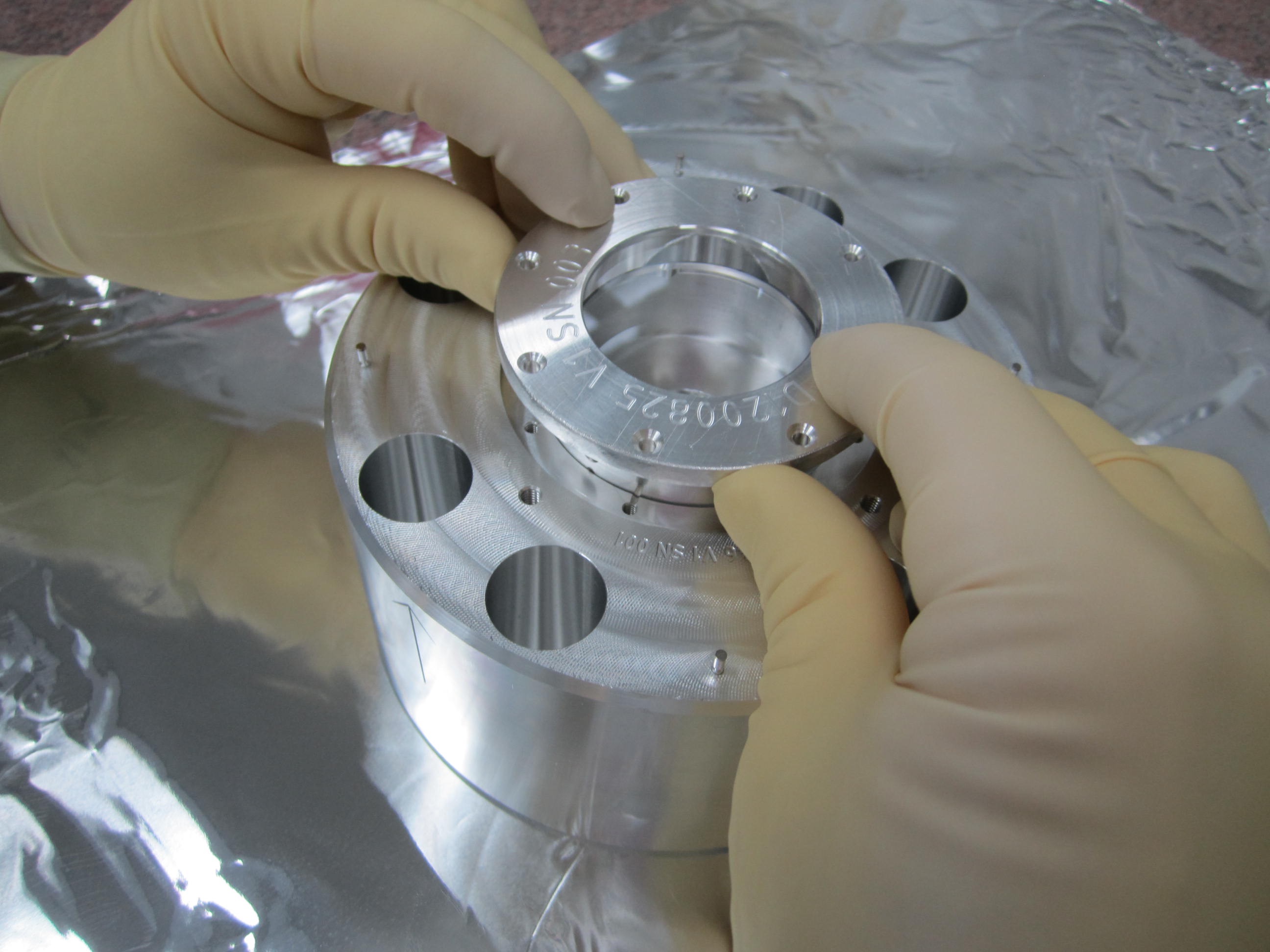
IMG_1475....Flipping the cup (with the optic in it) over and placing in main mass
IMG_1478....Cup now sitting in Main mass (without screws holding cup into main mass)
IMG_5172......the SRM surrogate installed into the suspension
It looks like there might be a mode in the L1 SRM at 2400 Hz. See the attached plot of SRCL error signal from January, along with DARM and the coherence. There is also a broad peak (hump) around 3500 Hz in SRCL, with very low coherence (0.04 or so) with DARM. The SRCL data has been scaled by 5e-5 here so that it lines up with DARM at 2400 Hz.
Here are two noise budgets showing the expected DARM noise assuming (1) structural (1/f1/2) SRM damping and (2) a hyperstructural (1/f3/4) SRM damping. This hyperstructural damping could explain the DARM noise around 30 to 40 Hz, but not the noise at 50 Hz and above.
I also attach an updated plot of the SRCL/DARM coupling during O1, showing the effect of the feedforward on both the control noise and on the cavity displacement noise (e.g., thermal noise). Above 20 Hz, the feeforward is not really making the displacement noise coupling any worse (compared to having the feedforward off).
Note that the PEEK thermal noise spectrum along with the SRCL/DARM coupling is able to explain quite well the appearance of the peak in DARM.
I am attaching noise budget data for the structural case in 27625.
