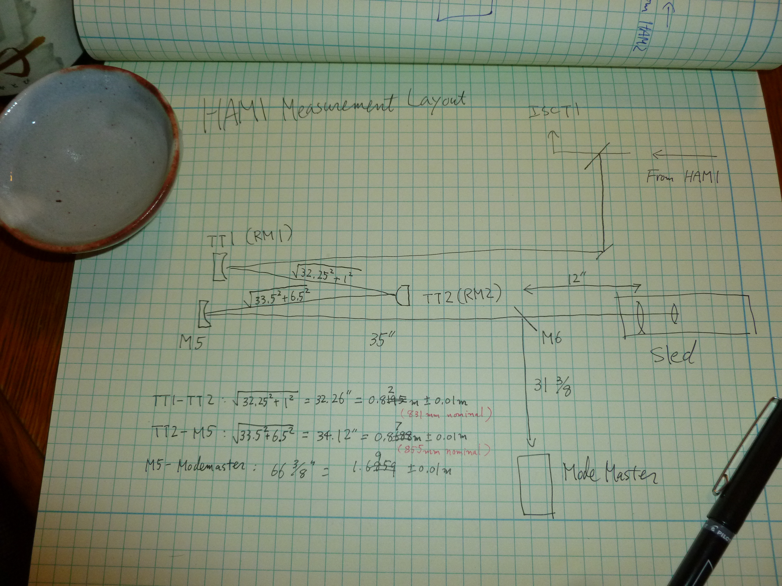
We placed Mode Master downstream of three-mirror Gouy phase matching telescope comprising two tip-tilts and one fixed mirror that is used for REFL WFS. (See the last picture for layout and distances.)
Note that the measured TT1-TT2 distance is about 1cm shorter than nominal described in Sam Waldman's document (http://dcc.ligo.org/T1000247), TT2-M5 distance is about 14mm longer than nominal, both of which should have been quite acceptable.
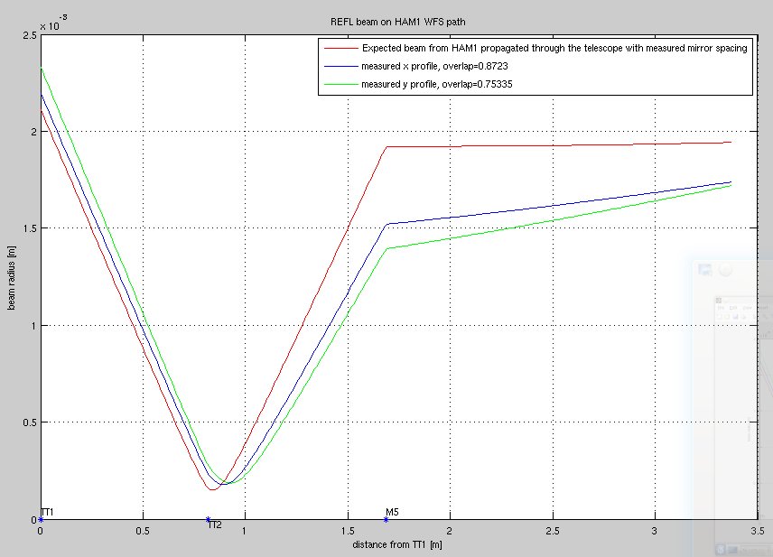
Anyway, we made this measurement and the beam was much smaller than what was expected. The first plot as well as the table below show the measured VS the expected mode profile coming out of HAM1 propagated through the telescope with the measured mirror distances.
| measured, x | measured, y | expected | |
| M^2 | 1.04 | 0.98 | 1-ish |
| Waist radius | 1.38 mm | 1.15 mm | 1.92mm |
| Waist position (away from MM head into HAM1) | 4.31 m | 4.35 m | 1.78 m |
| Mode overlap between measured and expected | 0.872 | 0.753 | 1 |
The total mode overlap between the actual beam and what is expected is somewhere between 0.75 and 0.87 (sort of tedious to do the real calculation so I leave it).
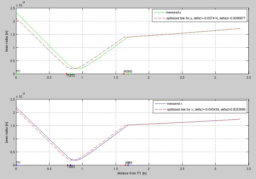
The 2nd plot shows that IF the incoming beam from HAM1 is as expected, in order to explain the measured mode the TT1-TT2 distance labeled as delta1 should be shorter by 4.5cm than was measured for X, or by 5.7cm for Y. This is a huge number, there's no way my distance measurement was that much off.
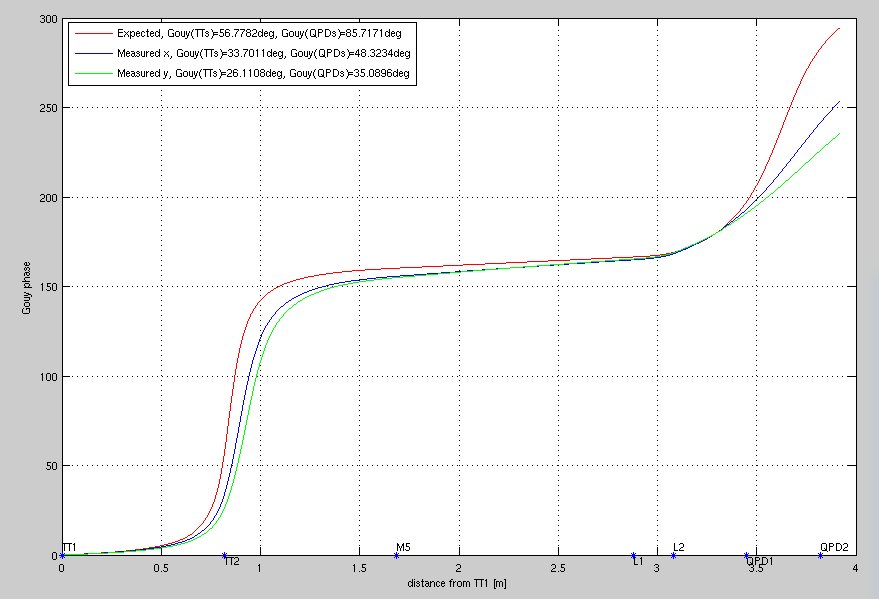
The 3rd plot shows the Gouy shift between TTs (i.e. actuation orthogonality) and WFSs for the WFS sled (i.e. sensing), and it seems like both are quite poor for the measured mode, 26deg for actuation and 35 for sensing are sad though not a complete disaster.
Anyway, since it's hard to imagine that the ROC of TT1 (+1.7m), TT2 (-0.6m) and M5 (+1.7m) are grossly wrong, and since it's hard to imagine that the distance measurement has a 5 to 6cm error, this should mean either (or some) of the followings:
- T1000247 is wrong about the mode coming out of HAM1.
- IMC mode is not mode matched to the IFO well.
- Astigmatism of curved optics at an angle (there are 3 such optics on HAM1, more on HAM2), each has small effect but maybe they add up. Neither Sam nor I have included this.
The third one doesn't sound likely, but neither Sam nor I have thought about this.

One quick thing to do is to measure the beam before it gets to the telescope by inserting M6 upstream of the TT1 to direct the beam to the Mode Master.
Yes, please, measure the beam before the TTs.
The original calculations were done by assuming that beam reaching HAM1 was perfectly matched to PRM.
I don't think we have reasons to believe that's true..
The "nominal" q of the beam right before the first tip-tilt RM1 is:

% REFL in-vacuum path beam propagation, HAM1 drawing v10
% https://dcc.ligo.org/LIGO-D1000313-v10
% LisaBar, August 14, 2013

q_in = 1.03+13.1i;  % Beam on HAM1 calculated from CalculatePRM.m
                    % Lisa: we don't have a measurement yet which confirms
                    % this number!
I don't think the table in T1000247 is correct. The beam from PMMT2 goes through the Faraday, hits PMMT1 and is then send to HAM1.
This is a) longer than 2.5m and b) adds PMMT1's curvature to it.
Did you include this?
Yes, PMMT1 is included, it is just a typo in the note (there are two PMMT2!).

Anyway, let's redo the calculations with the as-built parameters, and cross check with the measurements before the REFL telescope.
Kiwamu and Pablo and I measured the mode before the TTs by moving the BS for the RF detector to 16 inches after M2, with the front of the mode master 40 inches from the BS we measured:
| x | y | r | |
| M^2 | 0.97 | 1.03 | 1.00 |
| 2Wo (mm) | 3.588 | 3.532 | 3.567 |
| Z0 (m) | -2.387 | -3.578 | -3.026 |
The overlap between the mode measured before the Tip tilts and the mode measured after is 93% for X, 87% for Y.  I used Lisa's alm mode model attached to D1000313, added Keita's measurements of the distances from RM1 to RM2 and M5, but didn't include the tilt of the optics.

From this measurement before the tip tilts (projected through Keita's measurements of distances), the gouy phase separation is a little better than from Keita's measurement, WFS X=65 degrees, WFSY 60 degrees, TT x=56 TT y 50 degrees.
I checked to see how far wrong things in HAM2 would have to be in order to explain the beam waist sizes measured by Sheila before the tip-tilts.
I used the design parameters for IM2 and IM3 Rcs (except where varied), design parameters for HAM2 optics placement as found in E1200616 (except where varied), the measured value of PRM HR Rc of -10.9478m, and the design IMC parameters to get the starting beam parameter. The attached plots show the forward beam waist size (identical to the IMC waist size) and the return from PRM beam waist size, over variations in IM2 and IM3 Rc, and IM2->IM3 and IM4->PRM distance. At the design values (at the x-axis midpoint), the return x-waist size matches the forward waist size.
It looks like things in HAM2 would have to be further off from the design than is probably likely, in order to explain the measured beam waist size before the tip-tilts.

Propagating the IMC transmission beam through the "as-built" IMs, back from the PRM, off the FI rejected beam pick off mirror and onto HAM1 to the location where Sheila measured gives:
| axis | parameter | value |
| x | w0 | 2.123mm |
| y | w0 | 2.101mm |
| x | z | -2.469m |
| y | z | -2.150m |
| x | q | -2.469+13.310i |
| y | q | -2.150+13.035i |
| x | w | 2.159mm |
| y | w | 2.129mm |
| x | Rc | -74.21m |
| y | Rc | -81.16m |
I did not yet consider the calcite wedge polarizer effect on the beam parameter, and I didn't account for the thickness of the septum viewport.
The overlap of these beam parameters with Sheila's measured parameters are:
x overlap = 0.945
y overlap = 0.934
I'm including the Finesse kat file I used for the calculation, which has a list of all the parameters I used at the top. I also include that list here for convenience:
# H1_IMCtoPRC_matching.kat
# A file for checking the expected beam parameter in direct reflection from the PRM
# as a function of HAM2 optic RCs and placement positions
#
# Mirror curvature parameters taken from the nebula page, except IM2 and IM3 for
# which the design values were taken
#
# Distances taken from E1200616_v7 except where otherwise noted
#
# IMCC Curvature = 27275mm
# MC1->MC2 = 16240.6mm
# MC2->MC3 = 16240.6mm
# MC3->MC1 = 465mmm
# MC3 substrate path length = 84.5mm
# MC3-AR surface to IM1 = 428.2mm
# IM1->IM2 = 1293.8mm
# IM2 Rc = 12800mm
# IM2 AOI = 7deg
# IM2->IM3 = 1170.4mm
# IM3 Rc = -6240mm
# IM3 AOI = 7.1deg
# IM3->IM4 = 1174.5mm
# IM4->PRM-AR surface = 413.5mm
# PRM substrate path length = 73.7mm
# PRM Rc = 10947.8mm (from Rodica's measurement value)
# IM2->FIrejected pick off mirror = 1.012m (From Luke Williams)
# FI rejected pick off mirror->HAM1 mode master location =3.0175m (Estimated from
# Sheila's alog entry, HAM2 drawing, and 27.6" for HAM1 table edge to HAM2 table edge)
#####################################################################################

If anything, my measurement is a bit more suspicious than Sheila's, as mine is downstream of TTs in air and they are moving (mostly in PIT).
| axis | parameter | value |
| x | w0 | 2.121mm |
| y | w0 | 2.101mm |
| x | z | -2.583m |
| y | z | -2.154m |
| x | q | -2.583 + 13.29i |
| y | q | -2.154 + 13.04i |
| x | w | 2.161mm |
| y | w | 2.130mm |
| x | Rc | -70.95m |
| y | Rc | -81.05 |
Apparently I posted the last comment as Giacomo, sorry about that!
After discussing with Lisa about sign conventions for the beam waist position parameter, I realised that there are errors in some of the parameters I posted above. The mode master gives results as "z0" for waist position relative to the measurement position (z0-z), whereas Finesse gives results as "z" for the measurement position relative to the waist position (z-z0).
I had thought the convention was different, so I flipped my results to match the mode master convention. This was a mistake, because the conventions are the same, they just give different outputs. To get the q-parameter from the mode master results one should use the formula q = -z0 + i*zR. From the Finesse results one should use the formula q = z + i*zR.
This means that the z-values, Rc values and the real part of the q-parameters I posted should all have their signs flipped. Apologies for any confusion I caused here.