Closes FAMIS38887 , last checked in alog88362
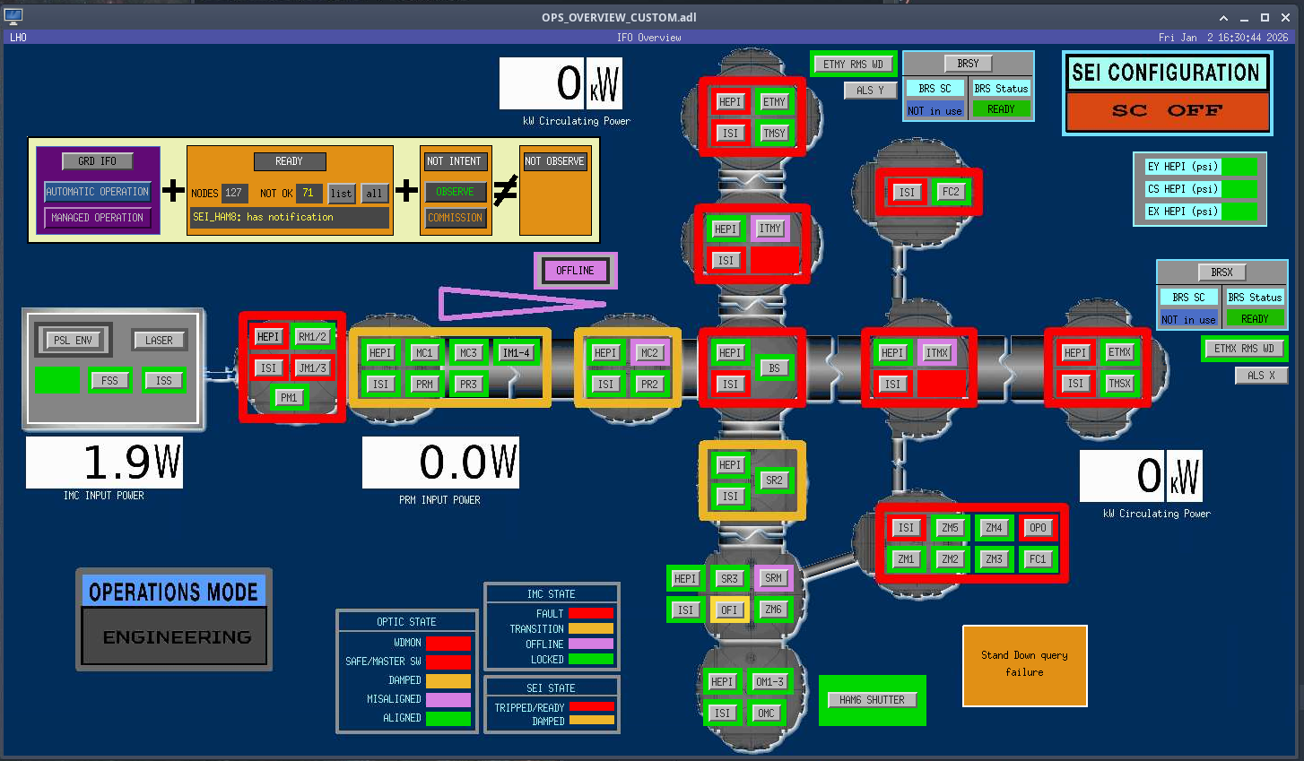
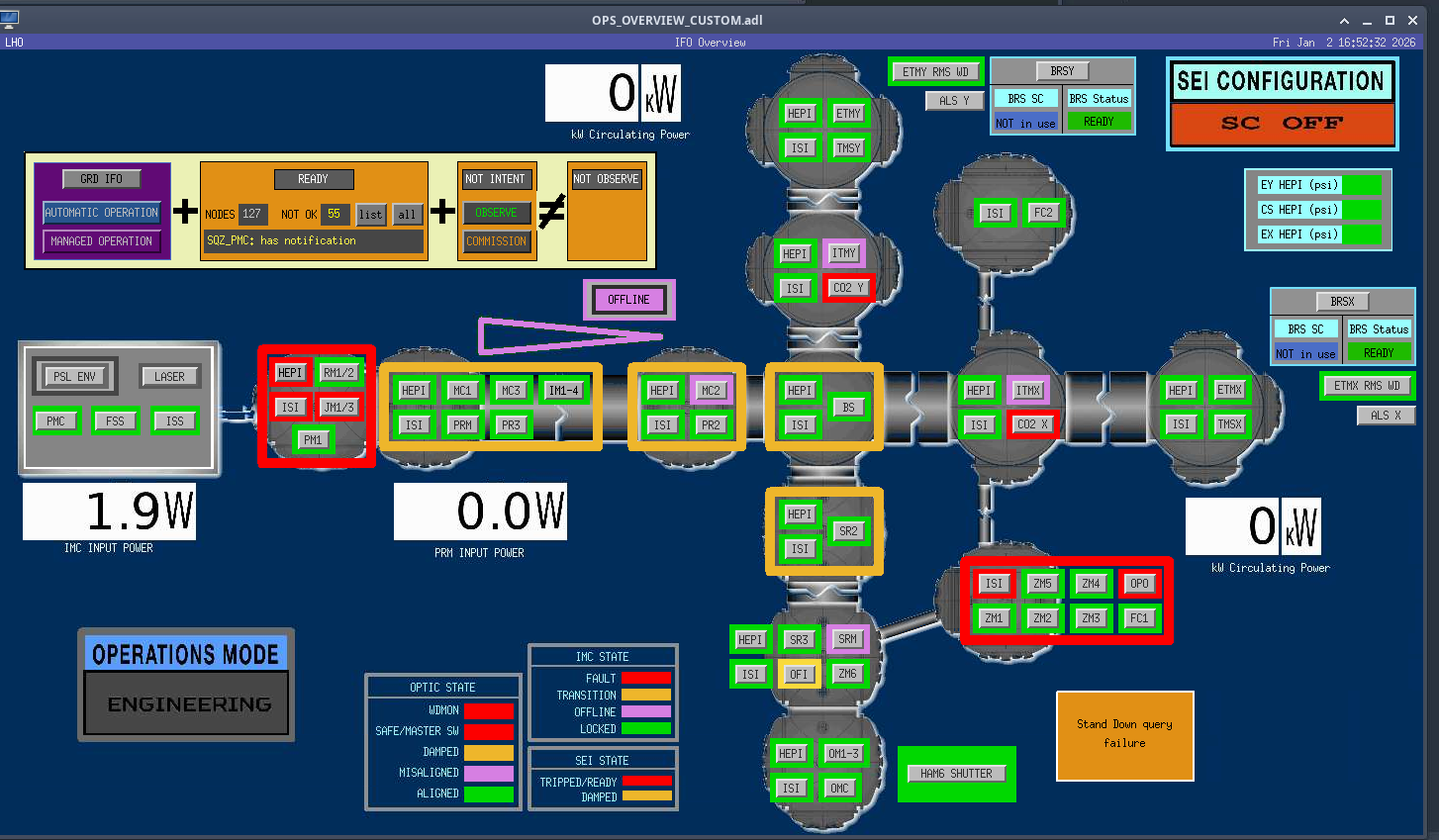
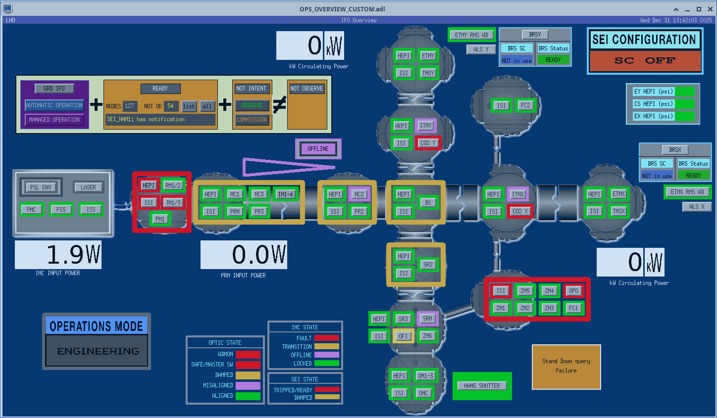
HAMs 1-4, 7 and BSC2 are in non nominal SEI states due to the vent work.
2026-01-05 08:58:15.266231
There are 14 T240 proof masses out of range ( > 0.3 [V] )!
ETMX T240 2 DOF X/U = -1.625 [V]
ETMX T240 2 DOF Y/V = -1.709 [V]
ETMX T240 2 DOF Z/W = -0.94 [V]
ITMX T240 1 DOF X/U = -2.28 [V]
ITMX T240 1 DOF Y/V = 0.313 [V]
ITMX T240 1 DOF Z/W = 0.485 [V]
ITMX T240 3 DOF X/U = -2.433 [V]
ITMY T240 3 DOF X/U = -1.065 [V]
ITMY T240 3 DOF Z/W = -2.971 [V]
BS T240 1 DOF Y/V = -0.372 [V]
BS T240 3 DOF Z/W = -0.449 [V]
HAM8 1 DOF X/U = -0.316 [V]
HAM8 1 DOF Y/V = -0.444 [V]
HAM8 1 DOF Z/W = -0.755 [V]
All other proof masses are within range ( < 0.3 [V] ):
ETMX T240 1 DOF X/U = -0.007 [V]
ETMX T240 1 DOF Y/V = -0.041 [V]
ETMX T240 1 DOF Z/W = -0.024 [V]
ETMX T240 3 DOF X/U = -0.016 [V]
ETMX T240 3 DOF Y/V = -0.069 [V]
ETMX T240 3 DOF Z/W = -0.045 [V]
ETMY T240 1 DOF X/U = 0.066 [V]
ETMY T240 1 DOF Y/V = 0.208 [V]
ETMY T240 1 DOF Z/W = 0.266 [V]
ETMY T240 2 DOF X/U = -0.075 [V]
ETMY T240 2 DOF Y/V = 0.226 [V]
ETMY T240 2 DOF Z/W = 0.049 [V]
ETMY T240 3 DOF X/U = 0.282 [V]
ETMY T240 3 DOF Y/V = 0.096 [V]
ETMY T240 3 DOF Z/W = 0.149 [V]
ITMX T240 2 DOF X/U = 0.158 [V]
ITMX T240 2 DOF Y/V = 0.283 [V]
ITMX T240 2 DOF Z/W = 0.263 [V]
ITMX T240 3 DOF Y/V = 0.139 [V]
ITMX T240 3 DOF Z/W = 0.086 [V]
ITMY T240 1 DOF X/U = 0.07 [V]
ITMY T240 1 DOF Y/V = 0.147 [V]
ITMY T240 1 DOF Z/W = 0.021 [V]
ITMY T240 2 DOF X/U = 0.021 [V]
ITMY T240 2 DOF Y/V = 0.239 [V]
ITMY T240 2 DOF Z/W = 0.152 [V]
ITMY T240 3 DOF Y/V = 0.085 [V]
BS T240 1 DOF X/U = -0.107 [V]
BS T240 1 DOF Z/W = 0.123 [V]
BS T240 2 DOF X/U = -0.031 [V]
BS T240 2 DOF Y/V = 0.038 [V]
BS T240 2 DOF Z/W = -0.052 [V]
BS T240 3 DOF X/U = -0.222 [V]
BS T240 3 DOF Y/V = -0.289 [V]
Assessment complete.
Averaging Mass Centering channels for 10 [sec] ...
2026-01-05 08:58:27.267417
There are 2 STS proof masses out of range ( > 2.0 [V] )!
STS EY DOF X/U = -4.63 [V]
STS EY DOF Z/W = 2.377 [V]
All other proof masses are within range ( < 2.0 [V] ):
STS A DOF X/U = -0.492 [V]
STS A DOF Y/V = -0.851 [V]
STS A DOF Z/W = -0.499 [V]
STS B DOF X/U = 0.153 [V]
STS B DOF Y/V = 0.944 [V]
STS B DOF Z/W = -0.303 [V]
STS C DOF X/U = -0.867 [V]
STS C DOF Y/V = 0.801 [V]
STS C DOF Z/W = 0.594 [V]
STS EX DOF X/U = -0.218 [V]
STS EX DOF Y/V = -0.16 [V]
STS EX DOF Z/W = 0.036 [V]
STS EY DOF Y/V = 1.254 [V]
STS FC DOF X/U = 0.161 [V]
STS FC DOF Y/V = -1.157 [V]
STS FC DOF Z/W = 0.625 [V]