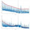
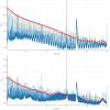
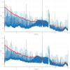
Below are the trends from the past 26 days as I have been on holiday and then out sick for a week.
A bit of a windy night made locking tough for commissioners. I worked on other items (alarm handler work, HAM5ISI trips, etc.).
The Commissioners will run the HWS measurement when they leave.
[Jenne, Sheila, Den, Hang, Keita]
We started the day by phasing the REFL WFS, both A and B, in both 9 and 45. In particular, we knew that the 45 MHz phasing was weird. Hang will post a reply with our detailed procedure.
We also reverted the AS 36 A&B demod phases to the values that Sheila had found on Sept 1 (alog 21083).
With this new phasing, we started trying to close WFS loops.
We captured the state of the ASC in a snapshot (saved in the same folder as the SDF's snap files), and then reverted everything to the down.snap file so that noise hunting work can happen tonight.
All of today's work was done in DRMI-only, since the wind was much too high to hold the arms with ALS. So, we'll have to re-visit these phasings, but hopefully they'll only be small tweaks in full lock.
We have not yet closed the loop on the new AS 90 centering loops, since we got a bit confused earlier in the day when (it turns out) there wasn't any light on the AS WFS. Keita has set gains and phases to match the current DC centering loop, so we should be able to just change the input matrix elements (same values) over to the AS 90 column.
Overall a good day, but we need to keep pushing forward.
The detailed procedrue we used to phase the REFL WFS' is summerized below:
### determining the relative phase of 4 quardrants using the length signal ###
Drive IMC_MCL_EXC with ~1000 cts at 4 Hz.
Turn on 4 Hz bandpass filters in I1-I4, Q1-Q4 filter banks
Phase s.t. the signal in each quardrant apears in I phase.
Looking at 4 I channels together to make sure no they are in phase and no sign flip.
Turn off MCL drive.
### checking the phase for alignment signals ###
Turn on resG filters in MICH, PRCL, SRCL.
Drive PR2 M3 by dithering pit or yaw, 1 at a time
Confirm I1, I2 in phase and I3, I4 opposite phase for pit; I1, I4 in phase and I2, I4 opposite phase for yaw.
Turn off PR2 drive; turn off resG in length loops; turn off bp filters in segments.
Done.
### step size for phase adjusting ###
1 deg for 9 MHz, 5 deg for 45 MHz
#########################################
Using the way above, the new phases for the REFL WFS are (in [deg])
old | new | |
A_9 | -97.5 | -74.0 |
-88.0 | -73.0 | |
-58.0 | -74.0 | |
-65.0 | -69.0 | |
A_45 | -165.0 | -115.0 |
-175.0 | -120.0 | |
-45.0 | -95.0 | |
-50.0 | -105.0 | |
B_9 | -83.0 | -83.0 |
-85.0 | -87.0 | |
-85.0 | -84.0 | |
-79.0 | -81.0 | |
B_45 | -245.0 | 0.0 |
-235.0 | 0.0 | |
245.0 | 10.0 | |
250.0 | 0.0 |
Kiwamu, Evan, Den We have continued ASC work in full lock. We concentrated on AS 36 signals since they are the most problematic. In the past we had to control SRM and BS using a combination of A and B, I and Q signals and switch them at different states. Tonight we have phased AS_36 A WFS in full lock and used only Q -> BS and I -> SRM signals during the whole lock acquisition sequence. This WFS is phased such that BS is in Q and SRM signal is equally split between I and Q. We did the similar phasing with AS_36 B WFS, but this diode has an offset and does not maximize the power. We have also noticed that phase of this WFS changes by 45 degrees when we increase the power. For these reasons we do not use it during the lock acquisition. We also noticed that when interferometer reaches 0 CARM offset, power recycling gain is around 33 and PRC WFS switch sign. We have updated the reference for ITMY camera servo in the initial alignment such that interferometer locks with high power recycling gain. We have also witnessed several lock losses in the state when DARM WFS are engaged and DARM is switched to RF from ALS. There is a large peak at 9Hz in the DARM loop with saturates the ESD driver. We should look more carefully into this issue.
Checked the PSL Crystal & Diod Chillers.
FAMIS #4138 is now closed.
model restarts logged for Wed 17/Feb/2016
2016_02_17 14:20 h1broadcast0
2016_02_17 14:20 h1dc0
2016_02_17 14:20 h1nds0
2016_02_17 14:20 h1nds1
2016_02_17 14:21 h1dc0
2016_02_17 14:21 h1nds0
2016_02_17 14:22 h1nds1
2016_02_17 14:22 h1tw1
2016_02_17 14:24 h1broadcast0
Unexpected crash of h1dc0 followed by in a bad DAQ restart.
Took about 3 minutes with LLCV bypass valve open 1/2 turn.
Next CP3 manual over fill is February 20 before 23:59 utc.
[Cao, Ellie, Dave O, Aidan, Kiwamu, Nutsinee]
To whoever will be the last to leave control room after commisioning tonight, we would like to run a script to test whether the beam on the Hartmann wavefront sensor is the beam coming from the HR surface of ITMY, here are the steps:
1. Turn off SR3 Cage Servo ,make sure that all mirrors are in ALIGNED state and set SUS for full lock.
2. Run a script named ringheaterITMY.py by entering "python ringheaterITMY.py" on the terminal (the terminal should have been already visible on the screen with the command).
This script will change the offset values:
SUS-SR3_M1_OPTICALIGN_P_OFFSET from 575.0 to 1574.8
SUS-SR3_M1_OPTICALIGN_Y_OFFSET from -153.6 to -336.2
We believe the beam on HWS at this position is the beam reflected from the HR surface of ITMY.
The script then will turn on the upper and lower ring heaters of ITMY to 1 W for 30 minutes and then turn off. This is the test for confirming the origin of beam spot on HWS.
The script is saved in folder HWSYAlignment folder in Home folder.
All relevant windows should be readily visible on desktop opsws3 10.20.0.133
J. Kissel, J. Warner Excited to use the buried STS (see LHO aLOG 25574), Jim had switched over to using the recently-moved-to-20 [m]-from-the-building STS for sensor correction (coupled with some other new configuration changes he's trying out; see LHO aLOG 25623). He was getting poor results when comparing internal vs external sensor correction use, so I've compared the times yesterday when we had great coherence at 10 [m] and 0-5 mph winds against today, when the STS is at 20 [m] away and there are consistent 25-30 mph winds. The message: both the internal and external ASDs, in X, Y, and Z, are comparable in amplitude and yet incoherent at this location and these 25-30 mph wind speeds. That means the buried STS is not so promising for sensor correction use at this level of wind. One can compare this to results originally presented by Robert at the 40 [m] location in ~15 mph winds; see LHO aLOG 19210. You'll notice that in both of these data sets, the contrast in amplitude difference between windy and not windy is "better" in the X DOF (perpendicular to the arm) than in the Y DOF (parallel with the arm; what we're trying to improve). We shall continue to take a smattering of data points to gather statistics at all wind speeds in this location. For the impatient and saddened -- recall that we have or will employ three different methods to attack wind at EY: (1) This buried, external STS [in the testing phase now] (2) A new BRS [scheduled for delivery in mid-March] (3) A wind screen system [working on getting funding] We're trying all three just in case one actually works. Let's hope one does!
J. Kissel More data on comparing the external, buried seismometer: - 20 [m] from the building, at 15-20 [mph] - 20 [m] from the building, at 5-10 [mph] - 20 [m] from the building, at 0-5 [mph] all of which are compared against the 0-5 [mph] data while the STS was 10 [m] away from the building. Conclusion -- there's really no substantial difference between the signal in these STSs at any wind speed between 0 to 30 [mph]. Bummer. Also note that the coherence for the no wind data at both 10 [m] and 20 [m] locations shows that the external instrument is behaving just as well after Robert moved it from 10 to 20 [m]. Perhaps we should move back to the 40 [m] location? That's where we'd seen the most dramatic results. Recall, the distance from the building is a balance between decoupling from building tilt (better further away) and frequency band where coherent (better closer to the building). At 40 [m] we were worried that we didn't get coherence (under no-wind conditions) out past ~0.5 [Hz]. But we'd only need coherence out to that high a frequency if we stick with the current 0.5 [Hz] narrow-band sensor correction; we don't have to -- we can explore moving to a lower frequency, broad-band sensor correction and re-allocate the feedback blend filters if need be. The message -- we need to do more work if we want this external STS to do us any good.
In December, I suggested a design for a new sensor correction filter for LHO. For most of the last month the end station ISI's have been running running this for a while, but I haven't had a good opportunity to do any comparisons of the interferometers performance. For now, I'll summarize the changes to the end station's configuration. During O1, we used 90 or 45mhz blends on St1 X&Y (depending on microseism) and the .46hz sensor correction (stolen from LLO) from the ground STS to St1 CPSs. For a good portion of the last month, I've been running the end station ISIs with my useism sensor correction to St1 and I moved the .46hz sensor correction to St2. I think that this configuration has allowed us to use the 90mhz blends with higher microseism, but I still haven't come up with a measurement to show that.
My first two attached plots show the difference in X between these two configurations. The first plot is the St1 perfromance (T240's blue and red) and ground STS (pink and light blue). Dashed is with the "01" configuration, solid is with the current configuration. As expected the current performance loses some around .5hz, but gains a factor of 2-ish suppressio of the microseism. The second plot shows the St2 GS13s and ground. Green is the current configuration, brown is the O1 configuration. The current configuration (useism senscor on st1, and st1-2 senscor) does better most places except for some gain peaking around 50-60mhz. It would be useful to compare the current configuration to performance with the 45mhz blends, which suppress the microseism better, but have more gain peaking below 100mhz and are adversely affected by wind.
The last plot shows the suppression (the transfer function from the ground STS to the St2 GS13s) of the 01(dashed brown) and current (solid blue) configuration. The story is the same, the current configuration does a better job between .1 and ~1 hz, a bit worse below .1 hz.
I have more configuration stuff to log, but I'm out of time for the moment. But HAM1 has inertial isolation, and I've added St1-2 FF in Z to the BSCs.
Heliax cable for the 71MHz CPS Sync was pulled in this morning. Cable goes from the CER to SUS rack H1:SUS-R3 (next to HAM4). Waiting on N bulkhead connectors for the 2U N patch panel.
The new EOM/AOM driver field cables (2 DB9 and 2 DB25) were pulled from the CER ISC racks to the PSL racks in the LVEA. Cables still need to be routed inside the PSL enclosure. For now, we left the old temporary field cables connected. These will need to be pulled out of the cable trays later on.
Here is the summary of the working SVN directories we have at LHO and the number of locally modified files in them pending commits to the repostitory.
repository | number of modified files |
userapps* | 218 |
40mSVN | 0 |
CalSVN | 32 |
CdsSVN | 0 |
DaqSVN | 0 |
IscSVN | 2 |
NbSVN | 53 |
SeiSVN | 1265 |
SusSVN | 55 |
* all working directories are under /ligo/svncommon/ except for user apps which is in /opt/rtcds/userapps
[Cao, Ellie, Dave O, Aidan, Nutsinee, Kiwamu]
We scanned SR3 last night for 7:50:00 (LHO alog 25600). We use Aidan's MATLAB script from LLO alog 9368 to identify beam spots on the HWSY. The three plots below are
1)HWSY_refl_map_early.jpeg showing the averaged intensity early in the scan
2) HWSY_refl_map_lin.jpeg showing the averaged intensity after full scan with linear intensity colormap
3) HWSY_refl_map_log.jpeg showing the avegaed intensity after full scan with log intensity color map
The spots look very different from that recorded at LLO as expected due to the wrong optics install in vacuum. The images of full scan show four beam spots. We first checked the source of two upper bright spots by misaligning the ITMY. There were no change in the bright beam spot observed on the HWSY. Therefore, these must have come from the 2 surfaces of the compensation plate (CP). The beam correponding to the left bright spot is currently centered on the camera.
We then checked the bright spot immediately underneath the current position of pitch and yaw (which is at the center of the plot). By misaligning the ITMY, we saw the beam spot on the camera move. By further adjusting the pitch and yaw of ITMY, we could see the beam spot disappear. Therefore, this beam must have come from one of the surface of the ITMY. The high intensity shown on SR3 scanning plot gives a strong indication that this beam comes from the HR surface of ITMY.
We will center this beam onto HWS this afternoon by walking the SR3 and periscope mirrors this afternoon. We are also planning to to run a definitive test tonight to confirm the source of this beam spot and see how far off we are from centering the beam by turning the ring heater on with the HWS running.
I've added all the filter gains to the MEDM screen as well so they can be clearly read (in-line after the corresponding button for each filter screen). These represent the steady-state diopters per Watt value for each actuator.
Richard put in the fix for TMSX satellite box and the oscillations are gone.
Had a couple of random HAM5 ISI/SRM_M1 watchdog trips. For both watchdog trips, it looks like HAM5ISI is first. The trips happened during two different states of working on H1.
1) At end of TJs shift when there was a lockloss from DRMI. The GS13s & Actuators both hit their limits. NOTE: on this one, SR3 was quite a bit off in yaw!
2) While aligning H1, HAM5 tripped in a similar way. NOTE: No issue with SR3 here!
For both cases, all the M1 OSEM RMS values start increasing (not enough to trip the WD), but it's interesting to see them all ramp up.
For the first case, Sheila made a change to Guardian to make sure we look at when DRMI drops out of lock. Still not really sure what caused case #2.
In the first case, plot 9, the ISC input goes up with a big ramp until the WD trip. Is it possible that SR3 was driven into the stop by some ?? control signal, and that the whack of the impact saturated the GS-13s (like the fast shutter on HAM6) which made the ISI trip? I don't see that in the second one, though. So even if true, that is not the only issue
Received an FMCS Air Handler HIGH RED alarm. This evening. I've acknowledged it, and it will probably stay in the RED state until addressed (if this is a new running state, we should update the alarm handler).
This might be correlated with John turning off heaters on Tuesday, but not sure.
Will send an email to John/Bubba.
Hmmm. I note that this seems to roughly correspond in time with our locking (and esp. alignment) troubles of the last 2 days.
A better representation of LVEA temperature is this signal:
H0:FMC-LVEA_CONTROL_AVTEMP_DEGF
see plot for the last 4 days.
Keita, Sheila
While the average temperature in the LVEA has been stable, the temperature has changed by about 1 degree C in several zones. Here is a plot of PR3 PIT (oplev and osem) as the temperature changes. These sensors could both be sensitive to temperature, but the optic could also have really moved with the temperature change.
It still seems plausible that our alignment difficulties of the last few days are related to temperature.
I filled the PSL diode chiller with 350ml of water. Attached is a 30 day plot showing where the diode chilller was filled on Feb 4th, and then the alarm level increasing starting around Feb 13th.
How does this alarm? Is it on Verbal? Audible alarm out in the Diode Room? Or is the red light the only way to tell if it's low. In general, the Crystal Chiller is the one which requires action every week. For the Diode Chiller all we have is the red LED to warn us of low levels (I've never seen it). We (operators) just need to remember to also keep checking the Diode Chiller when performing this task.
Conceivably, we check this every Thursday. If the alarm goes off on Friday, is it OK for this chiller to be in alarm until it's checked the next Thursday?
I wonder if we should include trending the alarm level on the FAMIS procedure for this as Cheryl did.
Unfortunately the red LED on the face of the diode chiller is the only alarm we have and checking this LED is part of the FAMIS procedure. Additionally, especially with Peter and I in Germany until mid-March, if anyone is in the diode room for any reason and sees this red LED lit, fill the diode chiller immediately until the light goes out and post in the alog that water was added and how much. If the water level gets too low, the chiller will shut off, which also shuts off the entire PSL. We need a better alarm (especially in the hypothetical situation Corey brings up, this could result in a laser shut down if not caught before the next scheduled check), but this is what we have for now.