Operators: If PI modes bounce during your shift - such as Mode26 and Mode18 - tune phase based on overall slope of the top of the bounces. The bouncing is not real (it's a filter issue I'm working on), but the overall height of the bounces is, so damp that as usual. This should only happen when two modes close in frequency are rung up at the same time, so you might need to be changing both phases during this time. Note that this will likely occur within the first half hour of powering up from a cold(er) state.
- - - - -
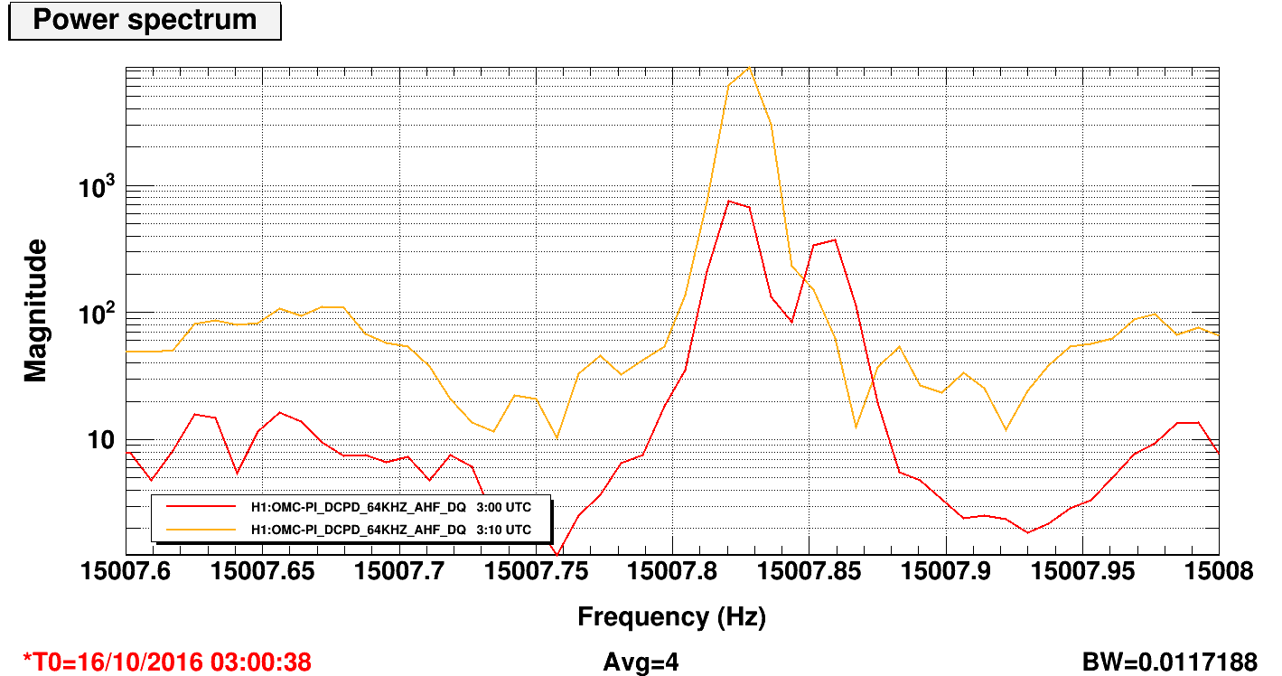
Since editing filters to help with the crossing modes - Mode18 and Mode26 - we've seen PI signals bounce on the PI StripTool several times now. I think this occurs during crossing when both modes are rung up; in this case, there are two peaks of similar amplitude within a few tenths of a Hz apart, the amplitudes are enough to engage the PLL, and the PLL(s) get confused about which peak is 'theirs' and end up jumping back and forth between the two. At the same time, bandpass filters are being turned on/off by the guardian, based on the frequency readback of the PLL's; the bounciness is caused by alternatively right and wrong BP filters being turned on, so the amplitude of peak appears to change dramatically as its within or outside of the bandpass.
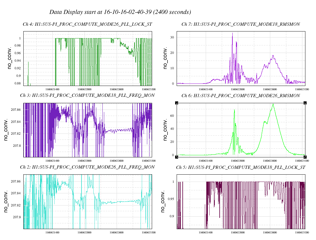
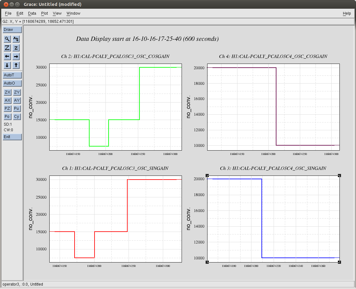
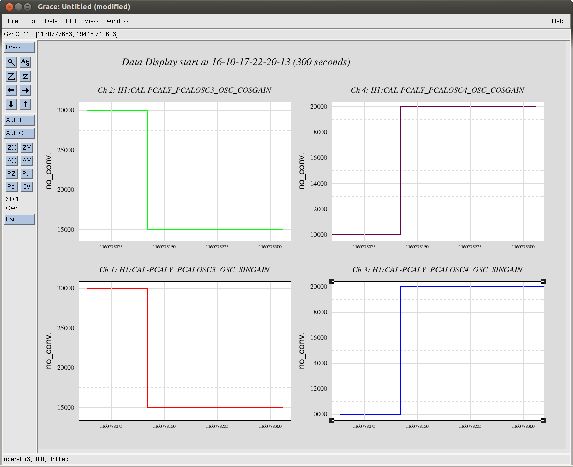
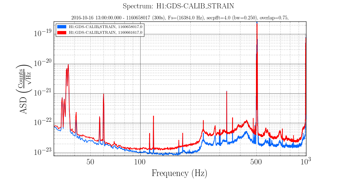
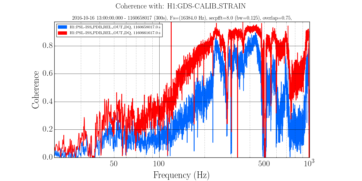
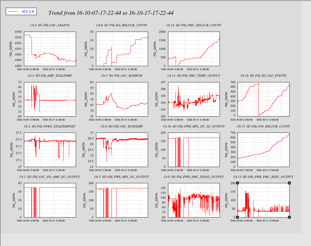
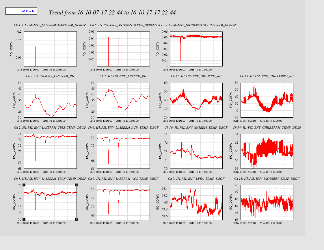
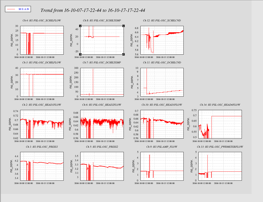
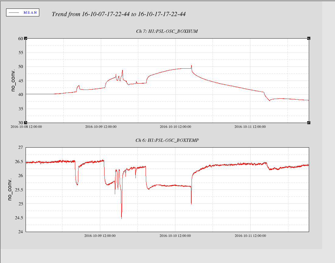
Attached are spectra during bouncy time when both peaks are elevated and during normal damping time (ten minutes later) when only one peak is high. Also attached are trends of relevant channels during this time. Bounciness seen in first bump in RMSMON channels, no bounciness ten minutes later in second bump. The FREQ_MON channels show the first bump correlating with strong switchbacks in frequency (especially in Mode18), versus single frequency tracking ten minutes later.
Still working on a good solution to handle this. For now, Mode's 18 and 26 have only been staying so close and rung up for periods of ~10 min and only during colder lock starts (after that Mode18 rises in frequency away from Mode26); we only saw this once over the full weekend of locking. And if we damp based on overall slope of bouncing, it's been damping well.