Nutsinee, Kiwamu,
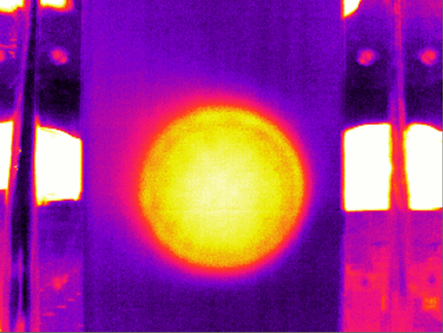
Today, we made a final touch on the alignment of the CO2Y table optics. As a result, we got a 5.7 W output power coming out of the table which is twice bigger than the value we measured back in April (26645). The beam profile now looks good -- almost axis symmetrical about the center of the beam area.
The next step: the alignment of the CO2 beam with respect to the interferometer beam.
[Details]
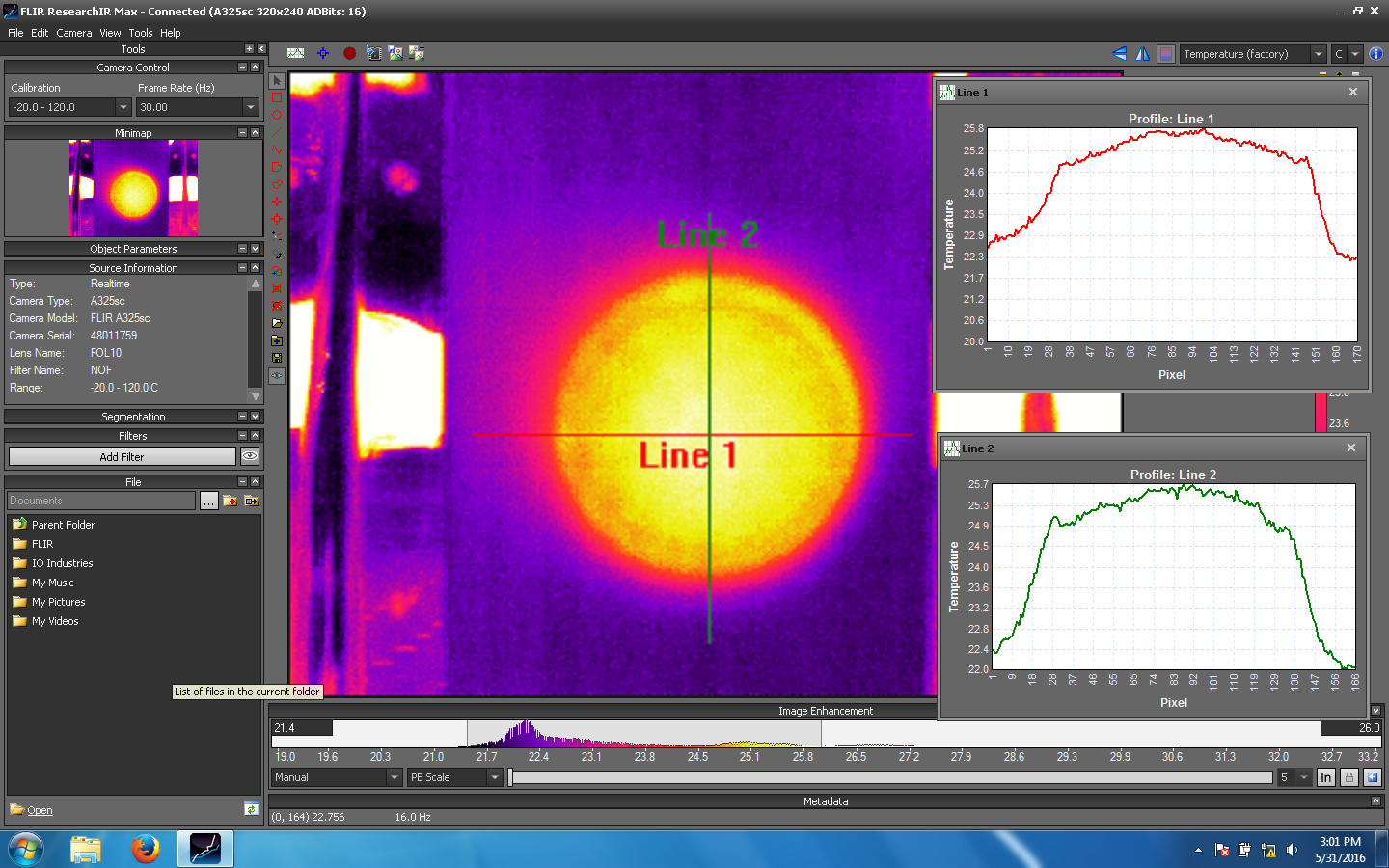
At the beginning, as a coarse alignment between the CO2 beam and the aperture mask, we moved the position of the mask by approximately a few mm in order to improve the horizontal beam profile. We then touched M5 in both pitch and yaw to further refine the alignment. Later we repositioned the beam dump which catches the reflection from the mask. This time, we used the FLIR camera as a reference which is much more sensitive than an image card with the UV light. The attached images are the ones after the fine adjustment.
Once we optimized the intensity profile, we re-aligned the beam through the two irises that have been serving as the fiducial points for projecting the beam to the test mass. After the alignment, we placed a power meter right behind the first iris which read 5.7 W when the rotation stage was at 18 deg (which should give us almost the maximum transmission). Before closing the table, we put the beam dump back in place to block the beam to the FLIR camera.