jenne.driggers@LIGO.ORG - posted 15:08, Friday 29 January 2016 (25251)
DHARD excitation stopped
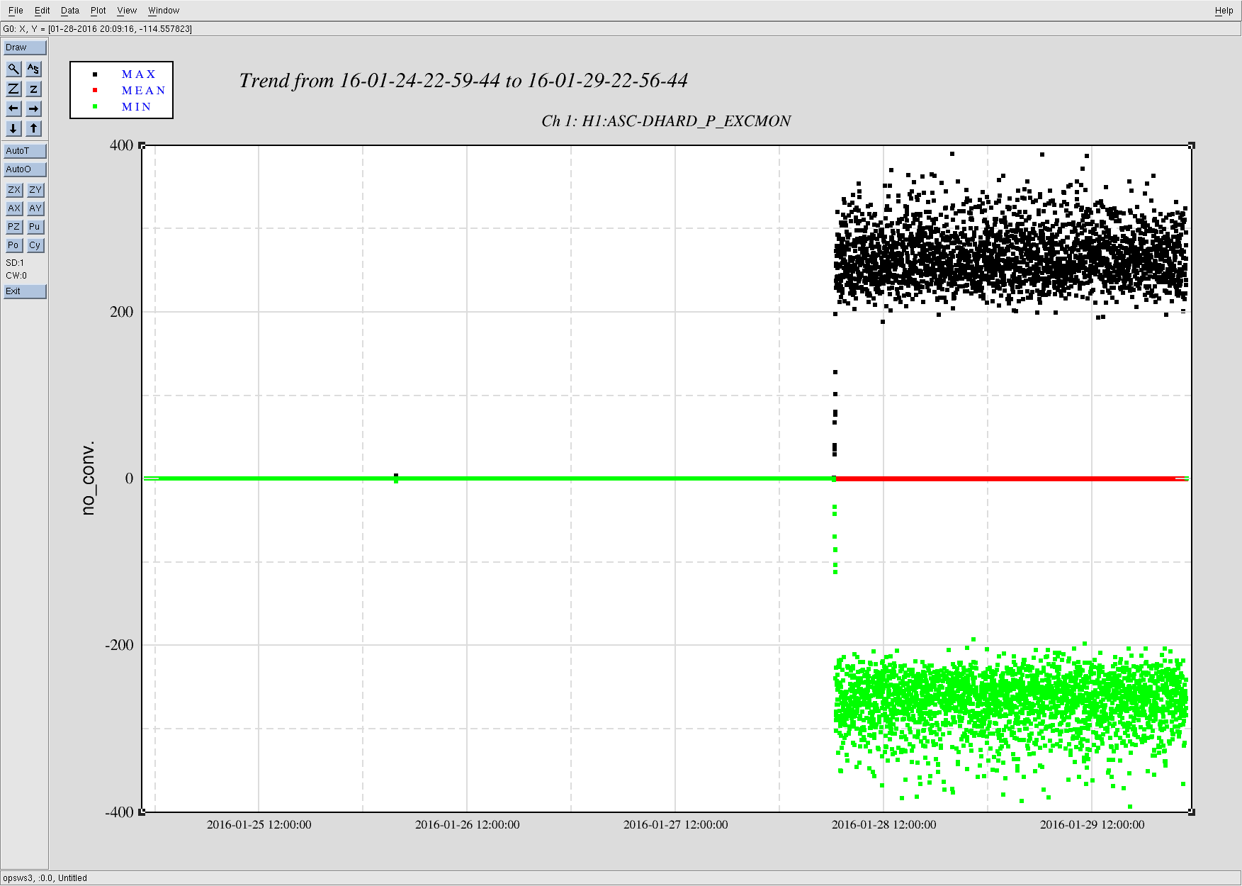
It looks like somehow Gabriele's DHARD Pitch injections (alog 25218) didn't get stopped properly on Wednesday night, and they've been going ever since. Ooops.
Gabriele thought that he stopped everything, and the workstation he was on has been logged out of and re-logged into by someone else, so I would think that awggui would have definitely stopped, but somehow it was still going. Anyhow, I cleared the test points for ASC and the excitation has actually stopped now.
Attached screenshot shows the excmon for the last 5 days. I don't know that this has prevented locking (Cheryl + commissioners had a 10+ minute lock earlier today), but it probably hasn't been helping.
Images attached to this report