kyle.ryan@LIGO.ORG - posted 16:12, Wednesday 27 January 2016 (25213)
Manually over-filled CP3
1545 - 1605 hrs. local -> To and from Y-mid

Next CP3 over fill to be Friday, Jan. 29th before 4:00 pm
1545 - 1605 hrs. local -> To and from Y-mid Next CP3 over fill to be Friday, Jan. 29th before 4:00 pm
State of H1: realigned and relocking and currently between DRMI and Engage ASC
Shift Details:
The picomotors for the TCS are as follows:
The following screens have been modified to fix links to the TCS picomotors so that they are correct:
All files have been committed to the SVN
Justin's web page contains a lot of very useful links, I have linked it at the bottom of the CDS home page.
I changed the label for button PICOMOTOR_H on the isc/commom/medm/ISC_CUST_PICOMOTOR_OVERVIEW.adl screen from "TCS HAM5" to "HWS table". I also changed the "name" argument associated with this button to "HWStable" so that this appears as the title of the picomotor screen that pops up when this button is pressed.
These changes were committed to the SVN.
Looking at the problems from last night I began looking at the ESD this AM. Noticing that the main read back for driver was flickering on and off I by-passed the LV driver and looked only at the HV driver. It was obvious the DC bias was not present. Hoping it was not the Driver itself looked at the incoming DAC channels and all functioned except the DC bias channel. Tracked it down to the output of the IO chassis. Filiberto replaced the 18bit DAC, ribbon cable and interface card. This cleared up the issue. While working on this noticed the ESD can get into some odd states when the on/off switch is pressed. I think we still have some binary issues that latch the unit up. Was able to clear the problem by going to the BIO screen and changing states.
Boards removed:
Interface Card - S1000865
18bit DAC - 101208-39

Boards Installed:
Interface Card - S1500234
18bit DAC - 101208-11
We've been working on a script to try improve the function of the rotation stage which controls the waveplate setting the power output to the CP. The script is now working, but we had problems yesterday with stability of the rotation stage control. The Y rotation stage stopped responding to requests. It's not clear what the cause of this problem is, but restarting the EtherCAT chassis for the rotation stages appears to fix the problem at least for a period of time. After a first restart the X-arm rotation stage which is currently in use, started to exhibit problems. The stage would correctly find home, but any angle request caused it to move randomly.
I re-calibrated the Y-arm rotation stage. The X-arm one does not appear to be correctly calibrated which may be a BURT restore issue. However this only affects calibration of power to angle, and should not affect operation for angle requests.
At this point I've completed the control script but don't plan on implementing it while the rotation stage is not working in a stable manor since the script asks the stage to move multiple times and may increase the tendency for it to fail.
Script is located at userapps/trunk/tcs/common/scripts/TCS_CO2P_SETPOWER.py
TJ, Laura
We've been working on tracking the RF45 glitches to veto them out of the astrophysical searches. We were initially tracking the control point of the RF45 MHz amplitude stabilization loop, H1:LSC-MOD_RF45_AM_CTRL_OUT_DQ, which seemed to be correlated with the severe glitching in DARM. However, as O1 progressed we noticed that the monitors we had built for this channel were missing some periods of severe glitching in DARM that we recognized as RF45 glitches. During these periods, the 45 MHz amplitude stabilization loop control point was completely quiet, but glitching was evident in MICH alignment degrees of freedom and DARM.
Since then, we've found that the most consistent witness to the RF45 glitches is a vertex alignment control signal, H1:ASC-AS_B_RF36_I_YAW_OUT_DQ. This signal is correlated with the glitches in DARM even when the 45 MHz amplitude control signal shows no discernable features. We've never seen any activity in the 9 MHz amplitude control signals during these glitchy periods. It doesn't seem like the amplitude stabilization of the 45 MHz sideband is the root cause of the noise in DARM, perhaps it's more of a witness to a broader issue in the RF electronics that commonly impacts generation of the 36 MHz signal.
19:42 UTC Started Conlog test code on conlog-test-master and connected it to the same 97,469 channels as the production code on h1conlog1-master.
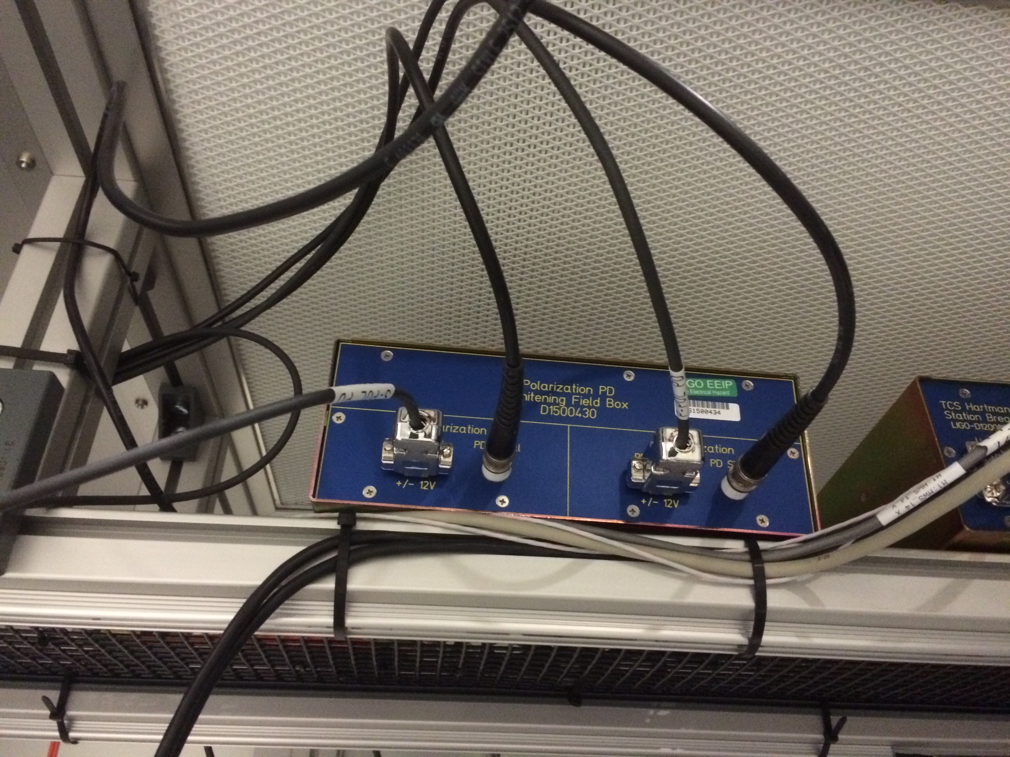
We added and aligned the fast photodetectors (PDA50B) to the HWS table, per T1500579. The outputs from these photodetectors go into a whitening board (D1500430). The input channels in the ADC are adc0_22 and adc0_23 in the TCS CO2 model.
We used an IR card with mounted in a C-Ring and the Green Beam from the ALS to align to the center of the aperture on the photodiodes. See the before and after alignment photos:
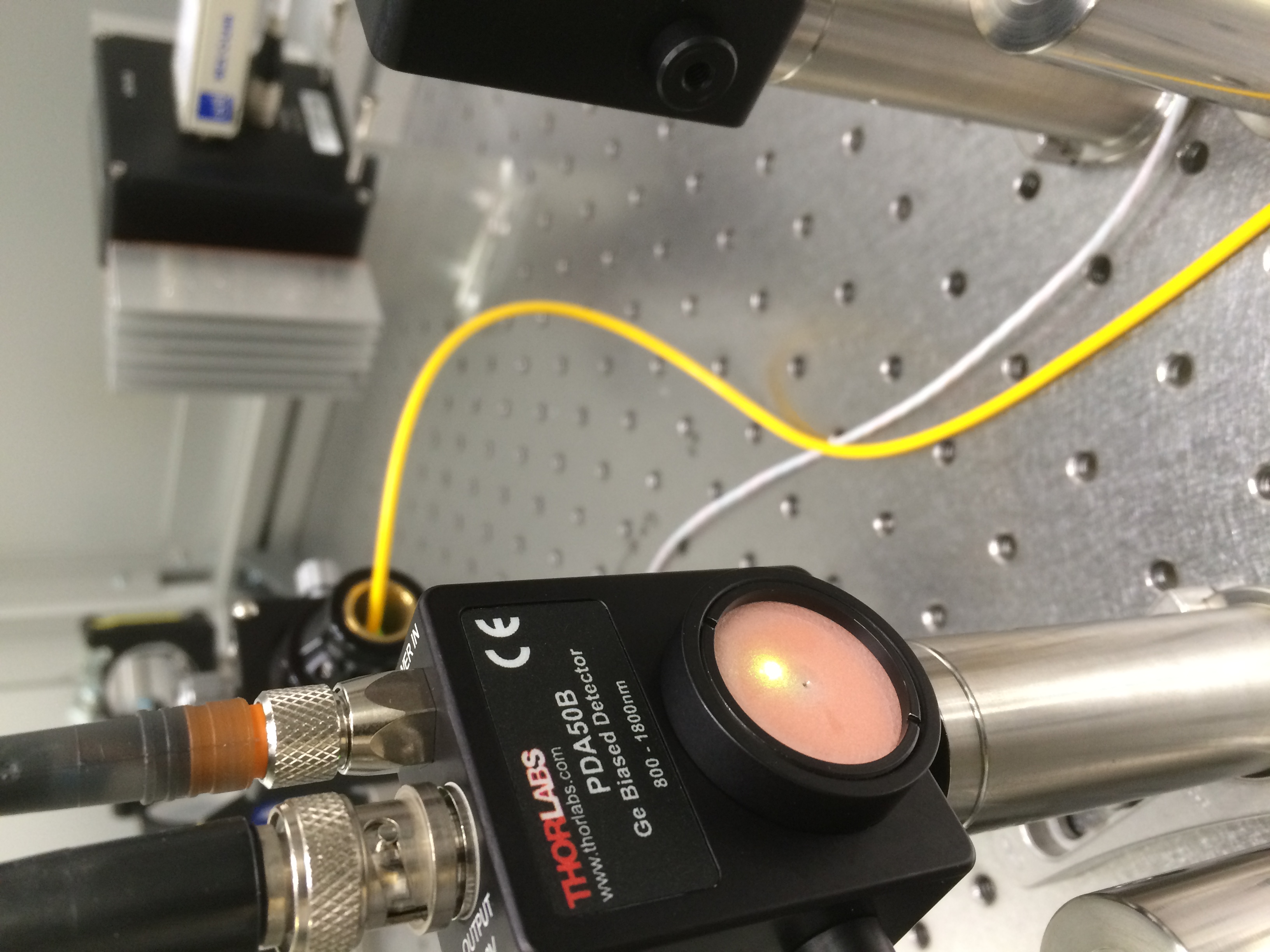
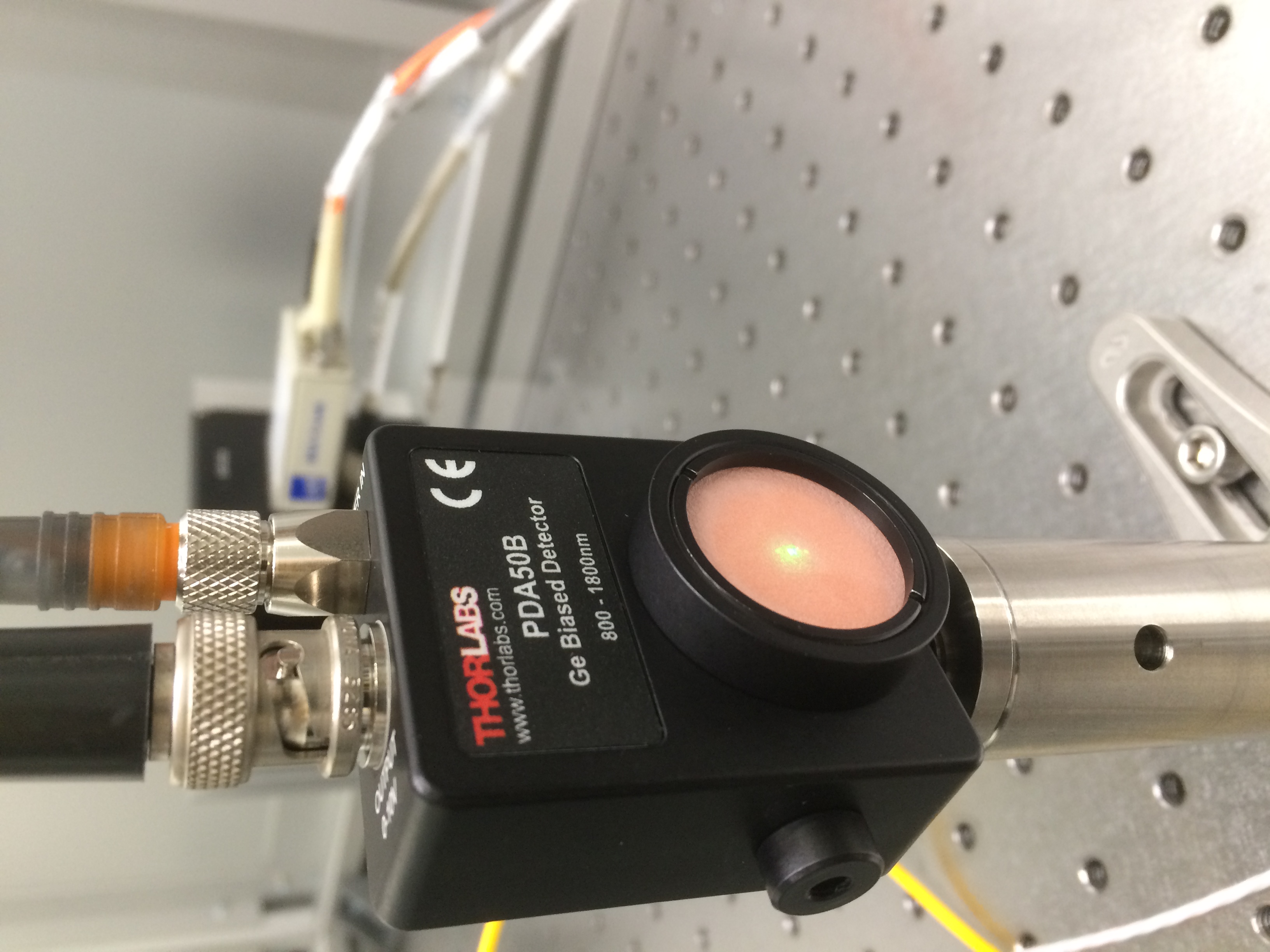
Also attached is a photo of the whitening board.
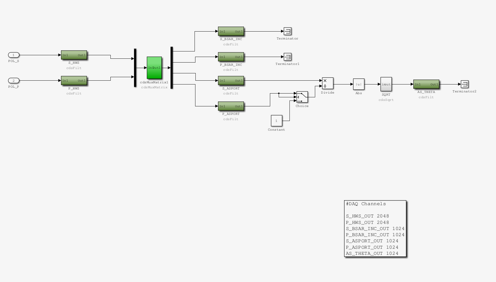
The input channels in the real-time code are: H1:TCS-IFO_POLZ_S_HWS and H1:TCS-IFO_POLZ_P_HWS.
The filter banks in these channels:
Also, the following DC offsets are added at the input based on measurements of the background value when the photodiodes were not illuminated:
From here, the outputs go into a 2x4 matrix for combination to produce S and P estimates for the power incident on the BS_AR surface. A rough estimate for these values are as follows:
Based on the complex reflectivites of the BS for S and P, the ratio of S to P at the AS PORT increases by a factor of 39 from the BS_AR surface. We use the following parameters to calculate the polarization angle (in radians) at the AS PORT.
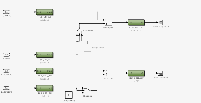
We made some changes to the TCS front end models yesterday morning:
- tcs/common/models/TCS_MASTER.mdl
Added two relative intensity noise channels for the IN-LOOP and OUT-LOOP photodiodes. They are constructed from the ISS_AC divided by ISS_DC (if ISS_DC <= 0, the denominator of this division defaults to 1).
New channels are: H1:TCS-ITMX_CO2_RIN_INLOOP, H1:TCS-ITMX_CO2_RIN_OUTLOOP and are saved to frames at 1024.
- tcs/common/models/TCS_POLZ.mdl
This is a new library block that takes the input from the IFO polarizaation sensors and creates channels that are S and P measurements at the HWS table, incident on the BS AR surface and at the AS PORT. There is also a channel that is an estimate of the polarization angle at the AS PORT. These new channels are all saved to commissioning frames at 1024
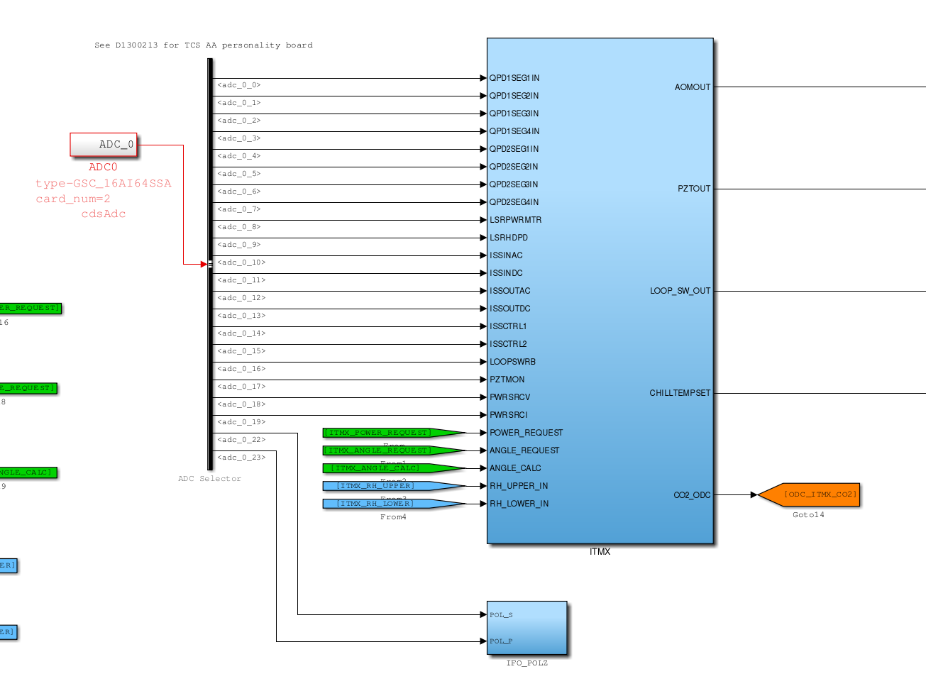
- tcs/h1/models/h1tcscs.mdl
Added adc0 channels 22 and 23 to the adc input. Injected these into the polarization block.
All these files were uploaded to the SVN.
State of H1: down more than 24 hours, ESD drive EY is restored to previous state (low voltage only)
Summary:
Powered off h1susey to allow I/O chassis to be power-cycled to try to reset an 18 bit DAC which has a channel that is not outputting values. On power up, the IRIG-B timing acted as if it were disconnected, the time was absurdly off and the GPS time was not accurate.  Powered off the computer, let it rest for a minute, and powered it back on.  This time the IRIG-B time came back with a good time.

The h1susauxey computer needed to be power-cycled because it's I/O chassis was shut off by mistake.

The channel on the 18 bit DAC is still dead, Richard is hunting down parts to replace it.  Expect the h1susey computer to be powered off again.
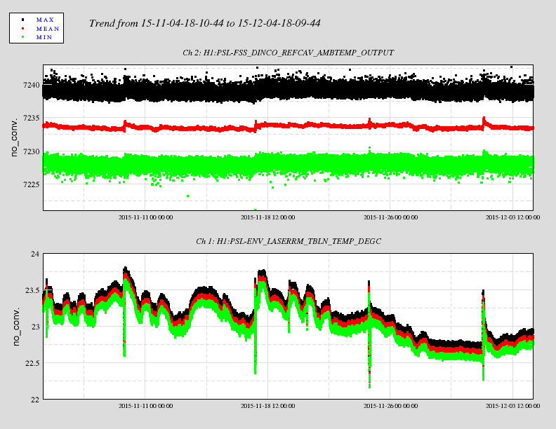
I have been trying to reconcile the difference in laser room temperatures as measured by a temperature
sensor on the PSL table and the PSL environmental temperature sensor.  Back tracking through the
schematics ... etc. the signal H1:PSL-FSS_DINCO_REFCAV_AMBTEMP_OUTPUT corresponds to approximately
-2.207 V.  That would imply that the ambient temperature is over 40 degC, which clearly it is not.
An infrared camera image suggests the ambient temperature is around 22 degC with a couple of people
inside the enclosure.

    What may account for the discrepancy?
 - broken AD590 temperature sensor
 - non-zero voltage coming out of the DAC card, which is the ambient temperature reference signal
 - broken LT1021-7 in the temperature box
 - something else I cannot account for (always a distinct possibility)

Will try and sort this out in the next few weeks.
[JimW, Jenne, EvanH, Kiwamu, Sheila, Gabriele]
We have tried several different kinds of channels, and DTT will only give you the first channel in the list. No good.
If you want to use the old version, in a terminal enter the command
source /ligo/apps/linux-x86_64/gds-2.17.1.1/etc/gds-user-env.sh
Then start diaggui in the same terminal.

I did some quick test.
The problem I found is that the channel data is fetched only when YOU SELECT THE CHANNELS FROM THE DROP-DOWN TREE SELECT BOX.
When you type the channel name into an empty channel, or copy & paste, that channel is ignored. This was not the case with older versions.
Once you select the channel name from the drop-down select box for a particular channel number, you can manually modify or delete and copy and paste an entirely new name for that channel number, and it works as expected.
Reported the problem to Jim.
Was going to submit an FRS for this, but see Jenne already did this (#4296).
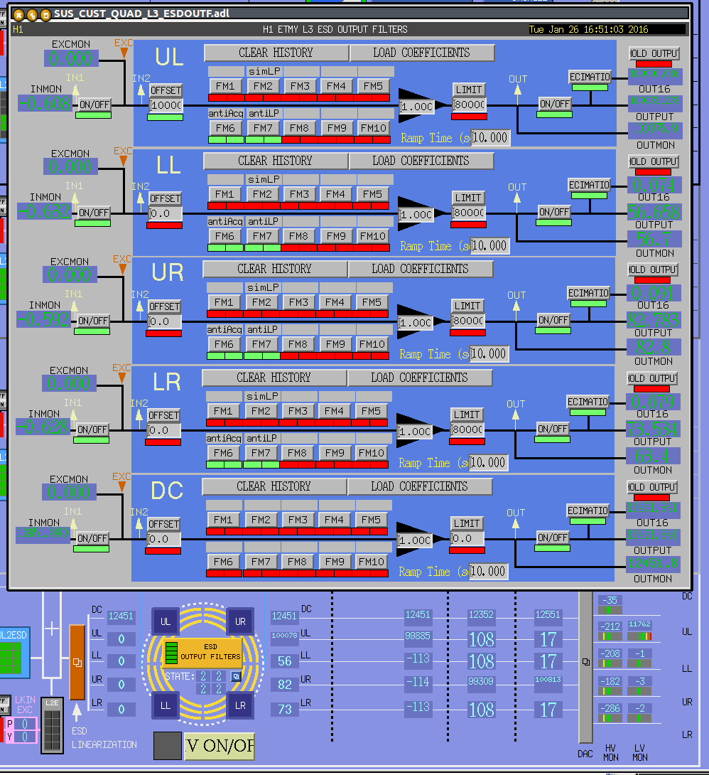
Jim, Evan

Does this behavior of the ETM ESD DAC outputs make sense? Here a large offset has been applied to the UL coil output filter. However, the screen suggests that it's being applied to the UR DAC channels.

This behavior is seen on both ETM ESD DACs, but not the ITM ESD DACs.
Hi Stefan,
It seems that the medm screen is not up-to-date. According to page 6 of D1002741-v10, the DAC order should be in BIAS, UR, LR, UL and LL starting from smaller channel number for the ESDs. The front end models (i.e. h1susetmx and h1susetmy) follow exactly what the document says, but the medm screen does not.
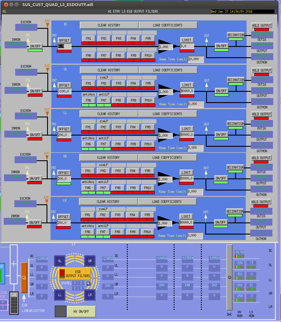
J. Kissel, S. Aston

The MEDMs were suffering from poorly updated macro substitution files, and other issues that was a result of the last minute addition of the LVLN driver before ER8. Stuart had fixed this problem at LLO months ago (see LLO aLOGs 18819 and 19356), but in the heat of battle at the start of the run we never imported the updates here.

A simple svn up of the
/opt/rtcds/userapps/release/sus/common/medm/
has solved the problem.

Indeed, I've taken it one step further, and modified
/opt/rtcds/userapps/release/sus/common/medm/quad/SUS_CUST_QUAD_L3_ESDOUTF.adl
to reflect the same order as what is shown on the overview screen.

Attached is a replica of the above screenshot, but with the fixed MEDM structure.
New lab dust monitors
Jeff B, Jim, Dave [WP5697]
As part of the install of the new OSB lab dust monitors:
generated new autoBurt.req file. Generated new DAQ EDCU INI file. Recanned conlog against autoBurt.req file.
New GDS version
Jim [WP 5696]:
completed this morning.
Clearing partially loaded filter modules
Was able to do full loads on susbs, susitmx, susitmy, susprm, sussrm. Still have partial loads on lsc, omc, suspr2 and sussr2 which are waiting for the system experts to clear.
DAQ reconfigure
DAQ EDCU was reconfigured for the missing h1tw0 and new DUST channels. Was applied during today's two DAQ restarts.
DAQ Restarts
In both DAQ restarts the dataconcentrator, tw1 and both framewriters started with no issues. In the first restart the broadcaster started by both NDS daqd process were no longer controlled by monit. A simple monit restart of the daqd processes cleared the error. On the second restart the broadcaster started, stopped and later restarted. Again both NDS processes did not start, and when they were restarted they failed. The error was that high dcuid nodes for the Beckhoff SDF system has been mistakenly added to the testpoint.par file, and only the NDS machines objected to this. The file was repaired and monit was able to restart the NDS daqd processes.
TCS model changes
Aidan and Dave [WP5688]:
Installed new h1tcscs model onto h1oaf0. DAQ was restarted.
New Beckhoff SDF code release
Jonathan [WP5695]:
Jonathan tested the new code on EY Beckhoff. He found an issue with enumerated binaries and backed this version out.
RACCESS monitoring/control of h1hwinj1
Jonathan, Jim, Dave:
Jonathan added the hardware injection machine h1hwinj1 to his RACCESS control system. MEDMs were updated accordingly.
H1OAF change to drive audio in control room
Richard, Evan, Dave [WP5704]:
h1oaf and h1pemcs models were changed to permit oaf to drive the 8th DAC channel of PEM's 18-bit DAC card. This analog signal is then routed from the CER to the control room using the audio channel in the digital video fiber link between the rooms.
New operator table install in the control room
Richard, Carlos, Jim, Dave:
The new powered, adjustable-height operator table was installed in the control room at the operator station. The access control PC, gate cam and alarm machines were shuffled to the left and a new workstation was installed on the new table.
HPI and ISI safe.snap work
Hugh, Dave:
Hugh worked on the safe.snap files for HPI and ISI. I was able to offer some help by creating a new script to convert sub-systems to safe SDF mode and converted all HPI and ISI to safe. Later I converted them back to OBSERVE mode.
New ECAT EPICS channels for corner station
Daniel, Dave:
Daniel made Beckhoff changes in the corner station. I updated the ECAT DAQ INI files and the target autoBurt.req files.
Server patching and rebooting
Carlos, Dave:
Carlos applied security patches and rebooted cdsssh, cdslogin and cdsadminctrl. We restarted the vacuum alarms system on cdslogin.
Note that at the time the DAQ was restarted during Tuesday's maintenance the DAQ dataconcentrator and both frame writers had been running continuously for 55 days 20 hours with no problems.
Xarm green alignment
Ed was struggling with the Xarm green alignment. We set the guardian to locked no slow, no wfs. I then turned on the loops one at a time. Usually the camera centering loops are the problem, but they were the easy ones this time. Eventually it was DOF2 that was causing trouble, so I had DOFs 1 and 3 closed and touched TMS by hand to get the error signals for DOF2 closer to zero. I was able to close all the loops, and let the alignment run like normal after that.
Xarm IR alignment
Not really sure what the problem is here, but it's getting late and I'm getting frustrated, so I'm going to see if I can move on with just hand aligning the input.
I suspect that the IMs need some more attention, so if Cheryl (or someone else following Cheryl's procedures) could check on those again in the morning, that would be great.
Also, I'm not sure if the RMs got any attention today, but the DC centering servos are struggling. I've increased the limits on DC servos 1 and 2, both pitch and yaw (they used to all be 555, now they're all 2000). I also increased H1:SUS-RM2_M1_LOCK_Y_LIMIT from 1000 to 2000.
Allowing the INP ASC loops to come on is consistently causing the arm power to decay from 0.85ish to lockloss. I didn't touch the ITM or ETM, but I'm not getting any more power by adjusting PR2 or IM4.
MICH Dark not locking. Discovered that BS's M2 EUL2OSEM matrix wasn't loaded, so no signal being sent out. Hit load, MICH locked, moved on.
Bounce needed hand damping (guardian will prompt you in DARM_WFS state), roll will probably need it too. This isn't surprising, since it happens whenever the ISI for a quad optic trips. Recall that you can find the final gains (and the signs) for all of these in the ISC_LOCK guardian. I like to start with something small-ish, and increase the gain as the mode damps away. No filters need to be changed, just the gains. My starting values are in the table below, and I usually go up by factors of 2 or 3 at a time.
| (starting gain values) | Bounce | Roll |
| ETMY | +0.001 | -1 |
| ETMX | +0.001 | +1 |
| ITMX | -0.001 | +1 |
| ITMY | -0.001 | -1 |
I lost lock while damping the bounce mode (in DARM_WFS state), and the DRMI alignment is coming back much worse than the first few DRMI locks I had.
I don't actually have a lot of faith in my input beam alignment, so I probably wouldn't be happy with any ASC loop measurements I take tonight even if I got the IFO locked. Since we have an 8am meeting, I'm going to call it a night, and ask the morning operator to check my alignment and fix anything that sleepy-Jenne messed up.
Evan, Kiwamu,
As some of us have already noticed, there is a broadband noise with a 1/f^{0.5} shape in frequency from 60 to 200 Hz. This noise is unidentified.
Do not believe any statements in this report until futher analaysis. Something is fishy with the claibration of the cross-spectrum.
We are planing to check how stable this noise level is over the course of the entire O1.
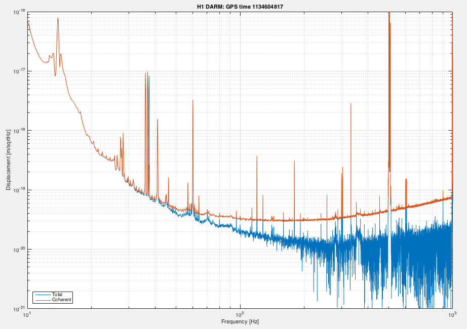
The below shows an example spectrum of DARM.
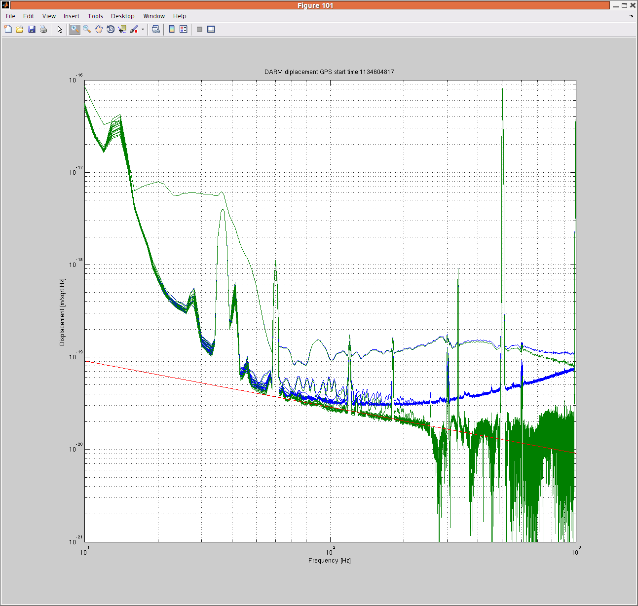
Blue curves are twenty spectra of DARM (aka C01 frame, converted into displacement), each of which is made by the Pwelch with Hanning, detrended, 50% overwrap for a 12 minutes time series. The data starts at a GPS time of 1134604817. Green curves are the square-root of twenty cross-power-spectra of DCPD A and B which are reconstructed from the sum and null streams of the DCPDs. The DARM suppression effect was removed from the sum signal. The cross-spectra are then calibrated to the displacement using the latest O1 DARM model of the calibration group. No time varying correction (i.e. kappas) is applied. Red line is a 1/f^{0.5} line to show how steep the slope of the green curves is. I also attach the fig file.
Gabriele, Evan, Kiwamu
There was a human-error in my code for calibrating the cross-spectrum. It was removing the loop suppression after the power spectrum of the null stream was subtracted from that of the sum stream. This was fixed such that the subtraction happens after the removal of the suppression in the sum spectrum. The below is the latest plot.
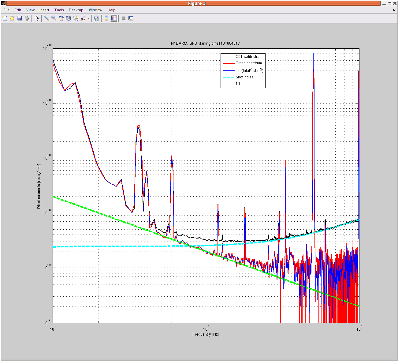
The plot shows the ampitude spectral desnsities of the calibrated darm displacement (aka C01) and the calibrated cross-spectrum. The cross-spectrum should represent noises which are coherent between two OMC DCPDs.
As a coarse verification, I have eye-ball-fitted the shot noise level with the fixed cavity pole frequency of 341 Hz (shown as a dotted line in cyan). Then I subtracted the shot noise component quadratically out from the actual displacement spectrum (in black). The residual (in blue) agrees with the estimation from the cross-spectrum. In order to check the slope of the cross-spectrum, I also drew a 1/f line. The cross-spectrum seems to follow 1/f from 50-ish Hz to 150 Hz.
The fig file is attached as well.
An update can be found in entry 25106
A higher resolution version is attached. The frequency resolution is set to 0.1 Hz, 50% overlap with Hanning for 1 hour data. No new findings.
The 1 Hz comb feature (see for example alog 24695) is becoming visible in 20-50 Hz. By the way, the legend in the plot is wrong.