J. Kissel, K. Izumi, J. Betzwieser
Since we've last taken the full actuation characterization measurement suite (see LHO aLOG 20940, T1500383), we've revised a few bits of the measurement methodology such that we might have more successful measurements. I recall them here to help us remember what we plan to do.
The major differences are as follows:
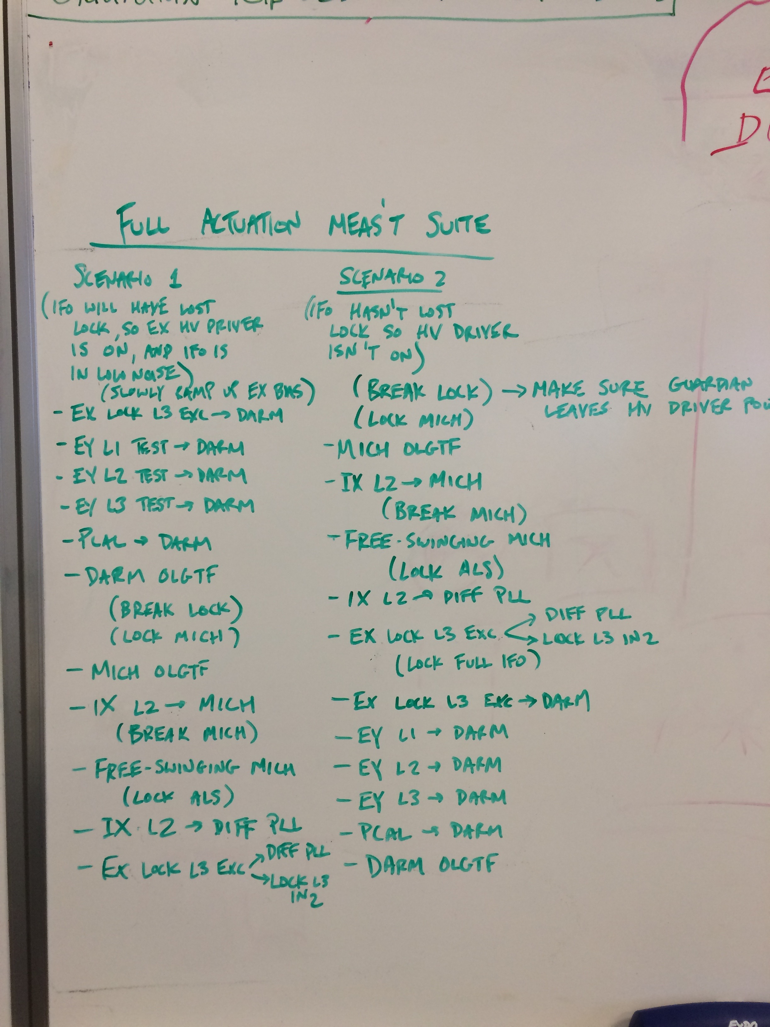
(1) Order of measurements (LLO innovation). In order to try to make the suite as robust against environmental or other reasons for lock-loss, Joe has suggested that we take the full IFO portions of the suite *first* while the IFO is stable and fully operational. These "final results" are really the only measurements that *need* to be in the same lock stretch, such that we can make sure that the optical gain of the FULL IFO is the same. Only after all 6 of those sweeps are complete, *then* we intentionally break the IFO and begin the ALS DIFF and Free-swinging Michelson measurements with lesser configurations of the IFO. The full outline of the measurements is attached as a picture.
(2) Merging of Free-swinging Michelson and ALS DIFF, IFO propogation measurements (LLO innovation). To-date, LHO has propagated the Free-Swinging Michelson absolute calibration from ITMX L2 stage to ETMX using the traditional single arm locked on red. However, during his last attempt, Joe had used ALS DIFF to propagate the the absolute calibration because (a) ALS DIFF is a more sensitive measurement and (b) we need to lock ALS DIFF anyways in our path propogate the ALS DIFF absolute calibration.
(3) Using the "super actuator" ALS DIFF transfer function (LHO innovation). This was mentioned in LHO's last attempt (see 20940). The idea being to reduce the number of seeps by one, by taking advantage of a little loop math:
From a simple diagram of the loop, one can show that
L3 LOCK IN2 1
----------- = ----------
L3 LOCK EXC 1 + G_DIFF
which is true with any excitation at any point around the loop, just like is done "normally" done with a DARM IN2 / DARM EXC TF. Further,
DIFF_PLL_CTRL 1
------------- = ---------- x ETMX x DIFF
L3 LOCK EXC 1 + G_DIFF
one can immediately see that the absolute calibration of the super-actuator ETMX falls out of ratio of these two transfer functions, assuming you have the absolute calibration of DIFF such that you can divide it out (i.e. the [Hz/ct] and z:p = 40:1.6 Hz pair of the VCO, i.e. measurements (3) and (4), which we do, a priori). What's great, is that since you're using the same excitation, as long as you store both of these channels in the template, you can directly measure and export the transfer function ratio that you really want,
DIFF_PLL_CTRL
------------- = ETMX x DIFF
L3 LOCK IN2
and thus you've reduced two measurments into one.