thomas.shaffer@LIGO.ORG - posted 09:46, Friday 13 November 2015 - last comment - 10:09, Friday 13 November 2015(23372)
Environment Update
Wanted to post some screenshots to show what we have going on.
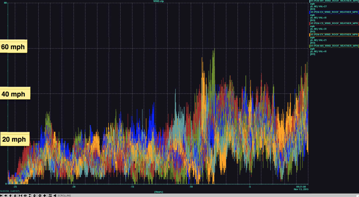
1st attachment - Wind Striptool
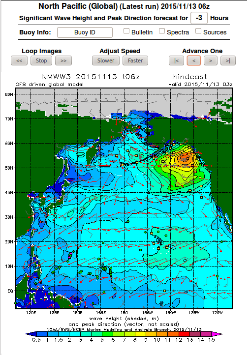
2nd - NOAA Wave height
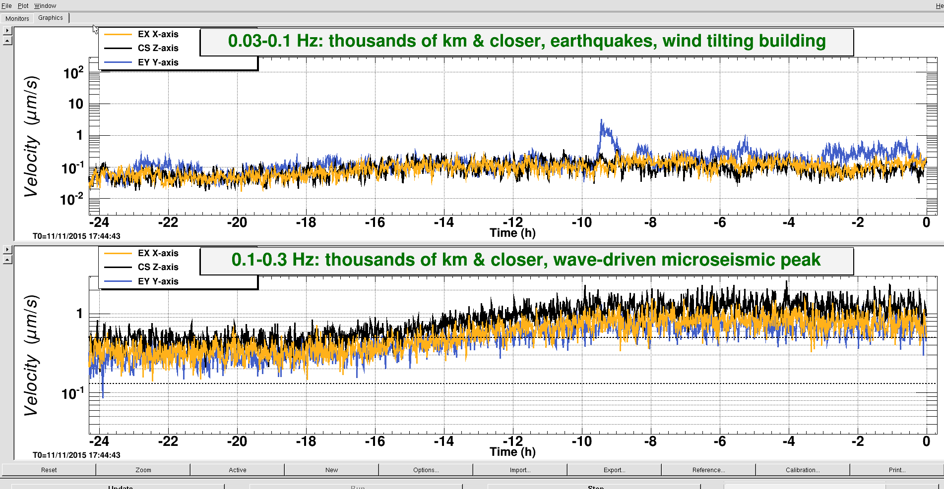
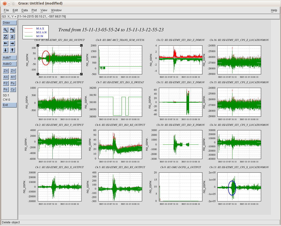
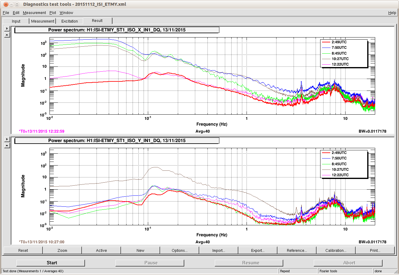
3rd - Seismic DMT in control room
Images attached to this report
Comments related to this report
Thanks for posting those - I was looking at wave heights earlier this morning and noticed the >10M waves off of British Columbia.

