jeffrey.bartlett@LIGO.ORG - posted 13:44, Friday 02 October 2015 (22187)
Ops Day Mid-Shift Summary
Working on relocking the IFO after this mornings lockloss
Working on relocking the IFO after this mornings lockloss
Chris B., Adam M.
Summary:
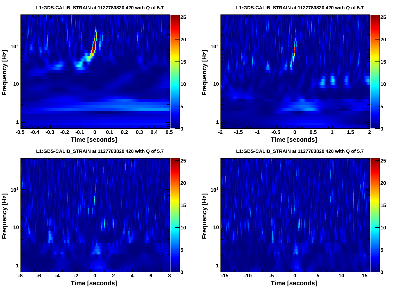
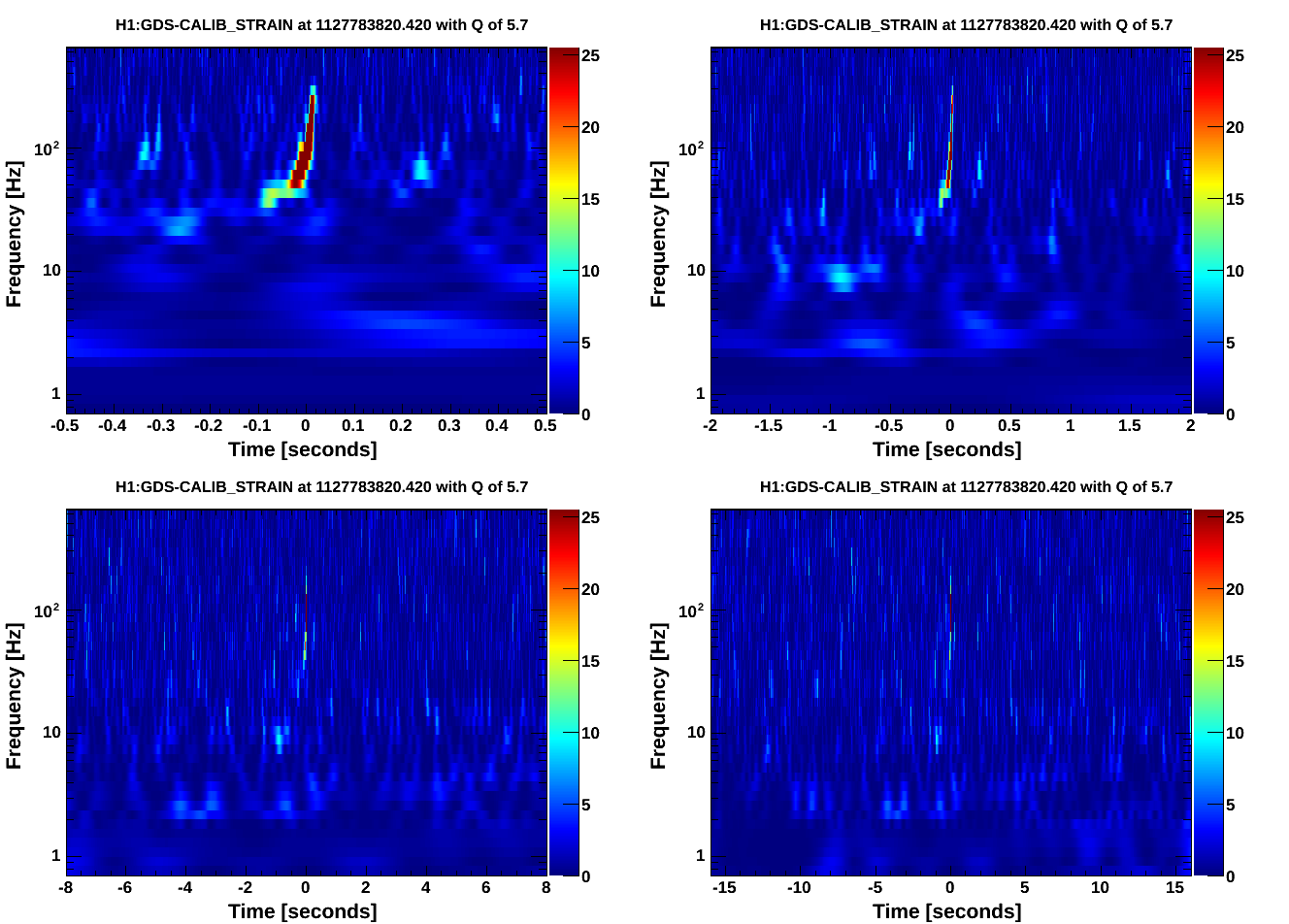
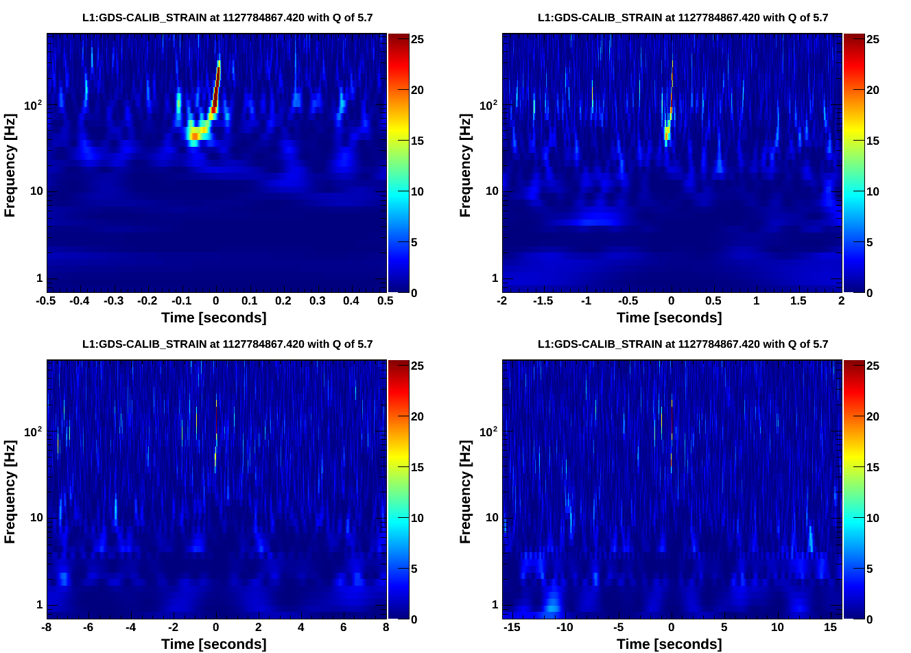
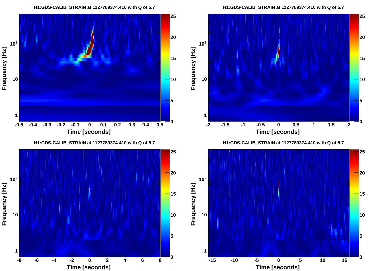
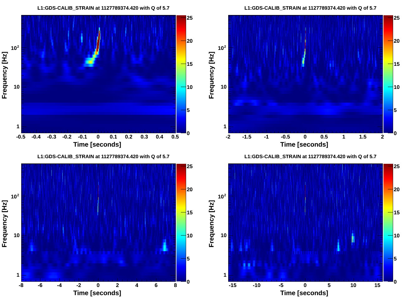
We tested scheduling CBC waveforms with tinj. We had two successful coherent H1L1 hardware injections and one failure.
I've attached omega scans of the hardware injections, except for the L1 omegscan for the injection scheduled at 1127789367 (will post this one later, there was an error generating it).
Waveforms:
All waveforms used are in the hardware injection SVN at: https://daqsvn.ligo-la.caltech.edu/svn/injection/hwinj/Details/Inspiral/${IFO}/coherentbbh*_*_${IFO}.out
And the parameter files are: https://daqsvn.ligo-la.caltech.edu/svn/injection/hwinj/Details/Inspiral/coherentbbh*_*.xml
Test 1:
Originally we scheduled one hardware injection. It was successful:
1127783813 1 1.0 coherentbbh0_1126259455_
The GraceDB events for this injection are L1 and H1.
Test 2:
We then scheduled another injection. It was successful at L1 and unsuccessful at H1:
1127784860 1 1.0 coherentbbh1_1126259455_
The GraceDB events for this injection are L1 and H1.
At the moment GraceDB is set up to treat hardware injections like EM alerts. In order to override the EM alert pausing of tinj and be able to schedule injections closer together on h1hwinj1/l1hwinj1 we did:
ezcawrite H1:CAL-INJ_EXTTRIG_ALERT_TIME 112775939
The command worked. And the injection was successful at L1. At H1 the injection did not go in. Checking the MEDM screen for hardware injections we saw that tinj was paused. We were not able to unpause it. We thought that maybe there was an outside process (GraceDB?) that was keeping tinj paused.
Therefore we removed the following scheduled injections from the schedule file:
1127785760 1 1.0 coherentbbh2_1126259455_
1127786667 1 1.0 coherentbbh3_1126259455_
1127787567 1 1.0 coherentbbh4_1126259455_
1127788467 1 1.0 coherentbbh5_1126259455_
1127790274 1 1.0 coherentbbh7_1126259455_
Since none of them would have been successful at H1.
Test 3:
We scheduled one last injection. It was successful:
1127789367 1 1.0 coherentbbh6_1126259455_
The GraceDB events for this injection are L1 and H1.
We checked that tinj was unpaused before this hardware injection and it was.
The reason the second scheduled injection didn't happen at LHO was because the version of ext_alert.py running at LHO is evidently an older version which is still setting H1:CAL-INJ_TINJ_PAUSE (alog 22171). So to allow injections closer together than an hour, it was necessary to manually change the value of H1:CAL-INJ_TINJ_PAUSE as well as H1:CAL-INJ_EXTTRIG_ALERT_TIME. Sorry, I didn't anticipate that when we were making plans for the injections earlier today.
Screenshot attached. We have fast glitches in the ALS Y arm transmission and control signals, which make lock acquisition difficult. In the past they have disapeared after a few hours. see alog 51242 and others referenceing it.
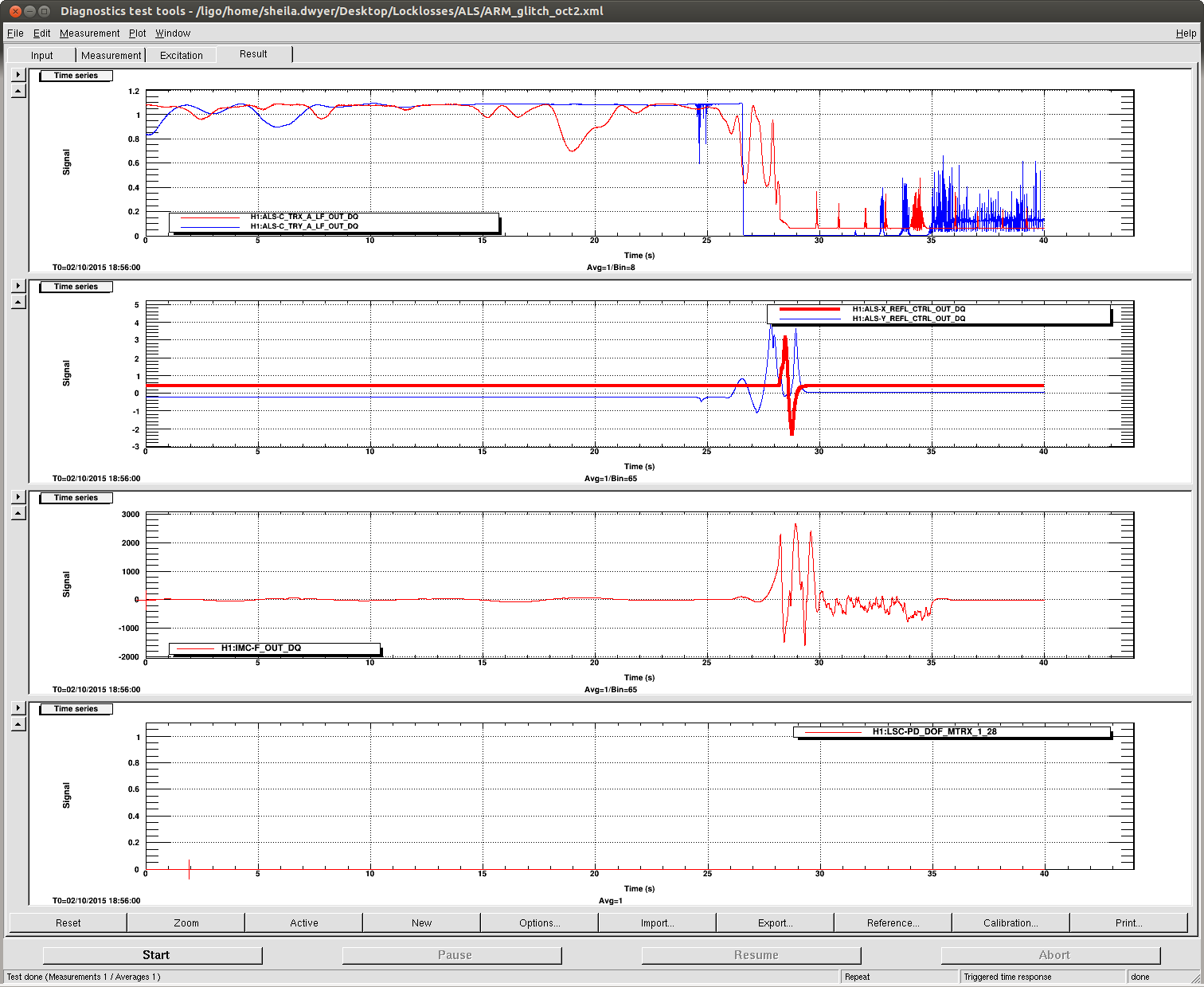
Daniel,Jeff B and I went to the Y end to look into this, and found nothing conclusive. We watched several signals on the scope. We see no signs of any problems on the fiber servo signals, or the PDH error signal, but it is clear that something is wrong looking at the PDH control signal. It is not saturating.
Jeff B droped out of observing mode around 15:38 UTC so that I could make some injections on the ETMX ISI to look for scattered light at end X (WP 5528).
I broke the lock by disabling the CSOFT P input. I have done this many times without breaking the lock before, but this time it clearly broke the lock. Relocking now.
Title:  10/02/2015, Day Shift 15:00 – 23:00 (08:00 – 16:00) All times in UTC (PT)

State of H1: At 15:00 (08:00) Locked at NOMINAL_LOW_NOISE, 22.9W, 74Mpc

Outgoing Operator: Jim

Quick Summary: No wind and no seismic activity. At the shift change, Jim had just finished recovering the IFO from an earlier lock-loss. Intent Bit set to Observing.
Title: 10/1 OWL Shift 7:00-15:00 UTC
State of H1: Low noise, finally
Shift Summary: Lost lock 10:00 UTC, next 5 hours spent trying to reacquire
Activity log:
Locked for first 3 hours
10:00 Lost lock
10:45 Figured out ALS-X wouldn't lock because of VCO issue, reset from VCO screens on ALS overview
12:30 Started initial alignment after several round of DRMI failure
13:30 Started initial alignment over again, after I realized I missed a step
15:00 Finally back to low noise, good luck Jeff
Lost lock about 45 minutes ago. Struggling to recover right now. First, it was dying at DRMI, but after a while I had a new issue with ALS, where the ALS-TRX arm power wasn't very good. I found an alog saying something about "reset VCO" but the log didn't say which one or how. There are 4 on the ALS overview, two of which said something about having run out of range. ALS-X guardian also complained of "VCO" and "PDH", with no more detail. After I got brave and reset "all" (2) the VCOs, the Y-arm ALS then wouldn't lock, so I had to touch up PR3 to build up ALS COMM. I'm now back to where I was right after the lock loss, waiting to survive DRMI lock.
Title: 10/1 Eve Shift 23:00-7:00 UTC (16:00-24:00 PST). All times in UTC.
State of H1: Observing
Shift Summary: Locked for the past 6 hours in Observing. Hardware injections took place. RF45 looks good. Calm wind and seismic.
Incoming operator: Jim
Activity log:
23:10 Fil back from MY
23:50 rebooted video5 computer due to frozen camera views
0:42 Observing mode
0:45 Chris starts HW injections
1:00 Kyle and Gerardo back from MY
2:55 restarted graceDB querying
Way back on September 5th, I collected OMC mode scan data before and after the power-up step from 2.2W to 22.5W. The idea was to measure the time-evolution of the sideband and higher-order-mode content at the AS port as the IFO thermalizes and the alignment adjusts to the hi-power state. During the mode scans, I followed Koji’s beacon demodulation technique, and used a DARM excitation to tag the carrier light resonant in the arms. This lets us disentangle the junk carrier light (resonant in the corner) from the good carrier light (resonant in the arms).
There’s quite a bit of information in these mode scans, but the major results are:
- After the power-up step, the amount of 9MHz light at the AS port more than doubles, with a time constant of about 6 minutes. I’m not sure how this informs the studies by Elli & Stefan and Paul regarding the AS36 WFS sensing. Does this time constant agree with thermal effects in the SRC? Or is it from slow alignment loops responding to something like wire heating?
- The contrast defect (ratio of carrier junk light to total available carrier light) is very small, less than 70ppm.
- The mode-matching of the carrier light resonant in the arms into the OMC is excellent, better than 99%.
- Unfortunately, these data don’t completely solve the mysteries of the HAM6 power budget. The 45MHz sidebands saturate the DCPDs at 22W with the preamps in the Hi-Z state, and this makes it impossible to measure the 45MHz sideband power at the AS port using mode scans. But, we can accurately measure the DCPD photocurrent from the carrier and 9MHz sidebands. Carrier = 33.6 +/- 0.4 mA, 9MHz SB = 34.9 +/- 0.3 mA.
Measurement Procedure
Here’s an outline of how the mode scan data were collected:
With the IFO locked on RF-DARM at 2.2W, unlock the OMC, turn off the OMC-LSC_SERVO output, turn off the OMC LSC dither. Turn off all stages of the the DCPD whitening (important).
Check that OMC ASC is on and using the QPDs. Zero the OMC PZT2 offset. Make sure the DARM boost (FM1) is on (important).
Set the DARM offset to 1.2e-5 counts in the LSC-DARM filter bank (this should be about 16pm).
Use AWG to set up an excitation on OMC-PZT2, I used a 70V ramp, 70 second period. Use AWG to set up an excitation on DARM for the beacon scan, I used 1e-8 counts at 201.7 Hz.
I collected ten minutes of data at low power, then engaged the power-up step in the Guardian. After power-up I collected about an hour of data. The GPS times of the data are:
Lo-power start: 1 125 478 482

	Lo-power stop:  1 125 478 992


	Hi-power start: 1 125 479 058

	Hi-power stop:  1 125 482 221
Mode Fitting
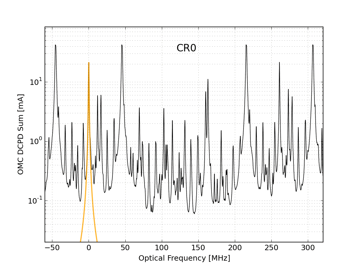
For each span of data, the analysis code looks at PZT2_MON_DC and finds times when the PZT drive was slowly increasing. During these periods it grabs the DCPD_SUM data and fits the modes, using the measured transverse mode spacing of the OMC and the known sideband frequencies. I use the measured FSR and f_HOM from Koji’s lab measurements of the H1 OMC:
FSR = 261.72 MHz

	f_HOM = 0.21946*FSR
The peaks are fit using the usual Lorentzian function of the PZT voltage. It would be better to do this as a function of optical frequency, but the PZT nonlinearity is small enough that I’ve ignored it. Anyways there's a chicken-and-egg problem, you have to fit the PZT voltage before you can convert voltage to optical frequency.
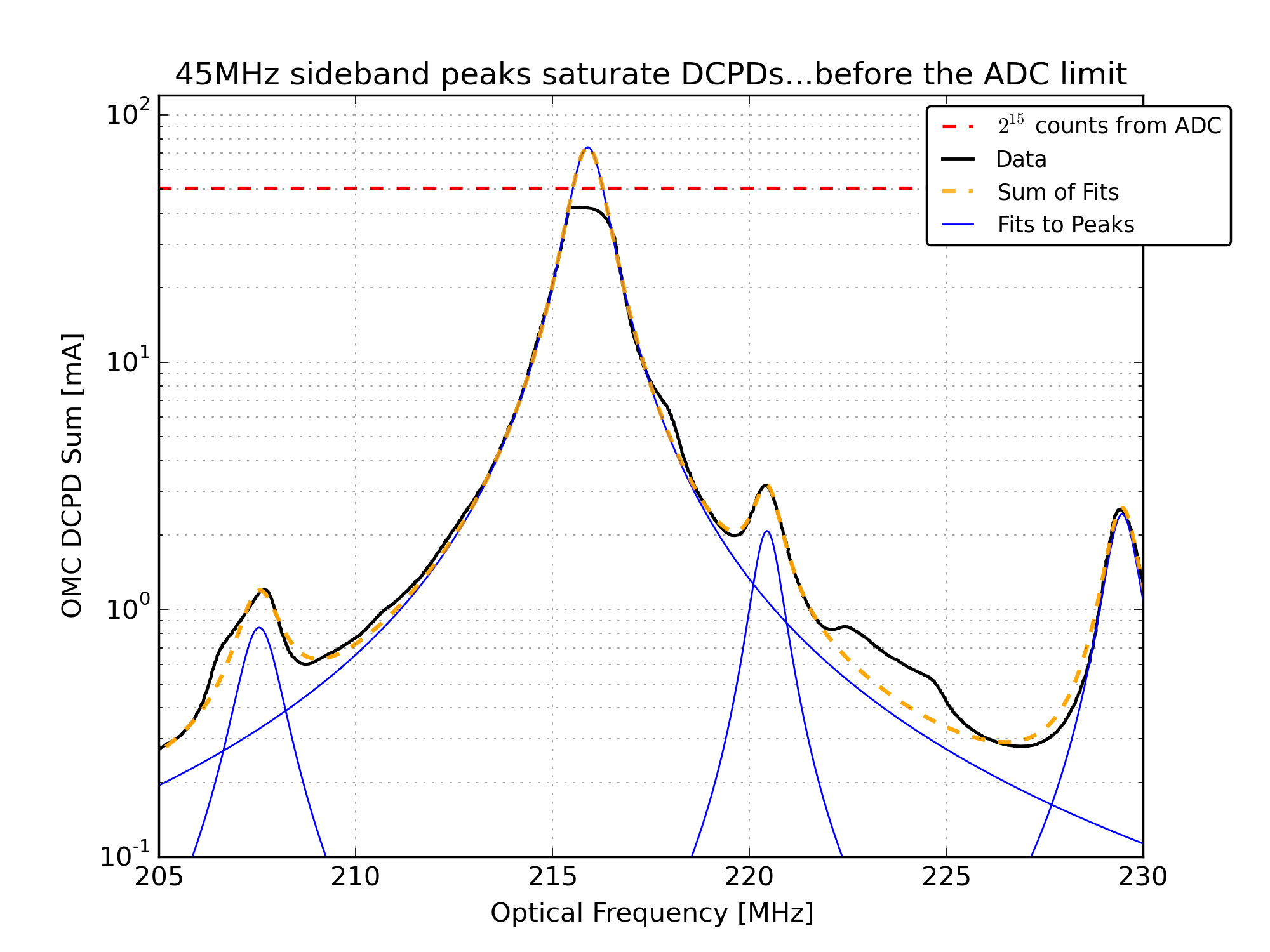
Problem: 45MHz sideband saturation
At 2.2W, the 45MHz sideband peaks generate about 16mA of photocurrent in DCPD_SUM. In the Hi-Z state, the DCPDs saturate at 20mA (the precise value varies slightly depending on the preamp electronics, these values have been recorded in, for example, the DCPD filter banks). At 22W we expect 160mA in each 45MHz peak, so these saturate the DCPDs.
Weirdly, the 45MHz peaks saturate at a slightly lower value than expected. During the mode scans each of the DCPDs would always flat-top around 27500 counts out of the ADC for each of the 45MHz peaks. See Figure 3. To get around this in the mode fitting, I fit the data before and after the flat-top from the saturation. Unfortunately this doesn’t return the correct peak height: the total power doesn’t agree with what we expect, and it doesn’t agree with the power measured by AS_C. So we still don’t have a complete picture of the HAM6 noise budget.
We could try mode scans with the DCPD preamps in the Lo-Z state, but this only gains us a factor of four in headroom, and the 45MHz peaks would still be on the edge of saturation.
Results: Contrast Defect, Mode Matching, and the Time Evolution of Sideband Power
Using the beacon dither demodulation, we can tag the fraction of the carrier modes which are resonant in the arm. For each PZT sweep, the DCPD data was demodulated at the DARM excitation frequency. A multiplicative factor was applied to match the carrier 00 mode signal in the demodulated signal to the raw DCPD data. From there, we calculate the fraction of each carrier higher-order-mode that is resonant in the arms. The procedure is the same as described by Koji. After some testing I settled on a 10Hz lowpass after the demodulation.
The junk light in the carrier higher order modes is used to calculate the contrast defect: 66.2 +/- 4.5 ppm. The uncertainty is a combination of the statistical uncertainty from mode heights and the variation from sweep to sweep, and systematic uncertainties described in section 5.6 of P1500136.
The fraction of good light in the CR2 (bullseye) mode is used to calculate the mode-matching of the resonant light from the arms into the OMC. Mode-matching: 0.997 +/- 0.001. The alignment into the OMC was not so good during these measurements (a large fraction of the CR1 mode was from the arms), but this was expected since we were using the QPD servo.
The breakdown of DCPD photocurrent from the carrier is:
34.00+/-0.06 mA total carrier light

	22.42+/-0.06 mA of light from the arms (note: this is not quite the standard DARM offset)

	11.59+/-0.06 mA of junk that's not from the arms
Probably in typical low-noise operations, we have 20mA of carrier light from the arms (fixed by the DC readout loop), and 11.6mA of junk carrier from the corner.
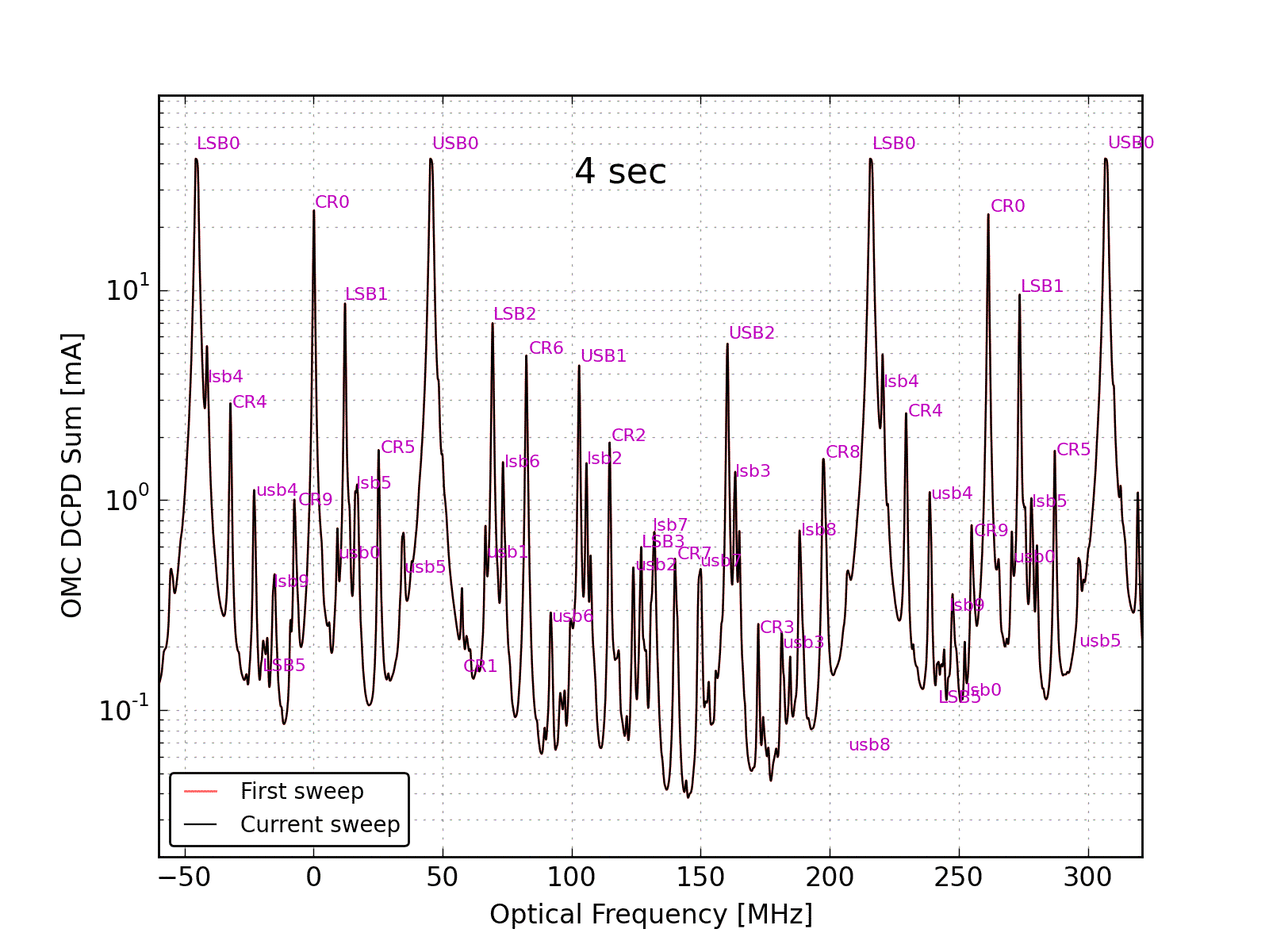
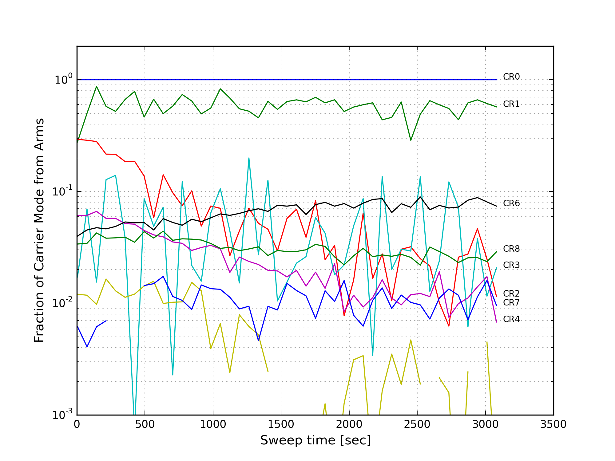
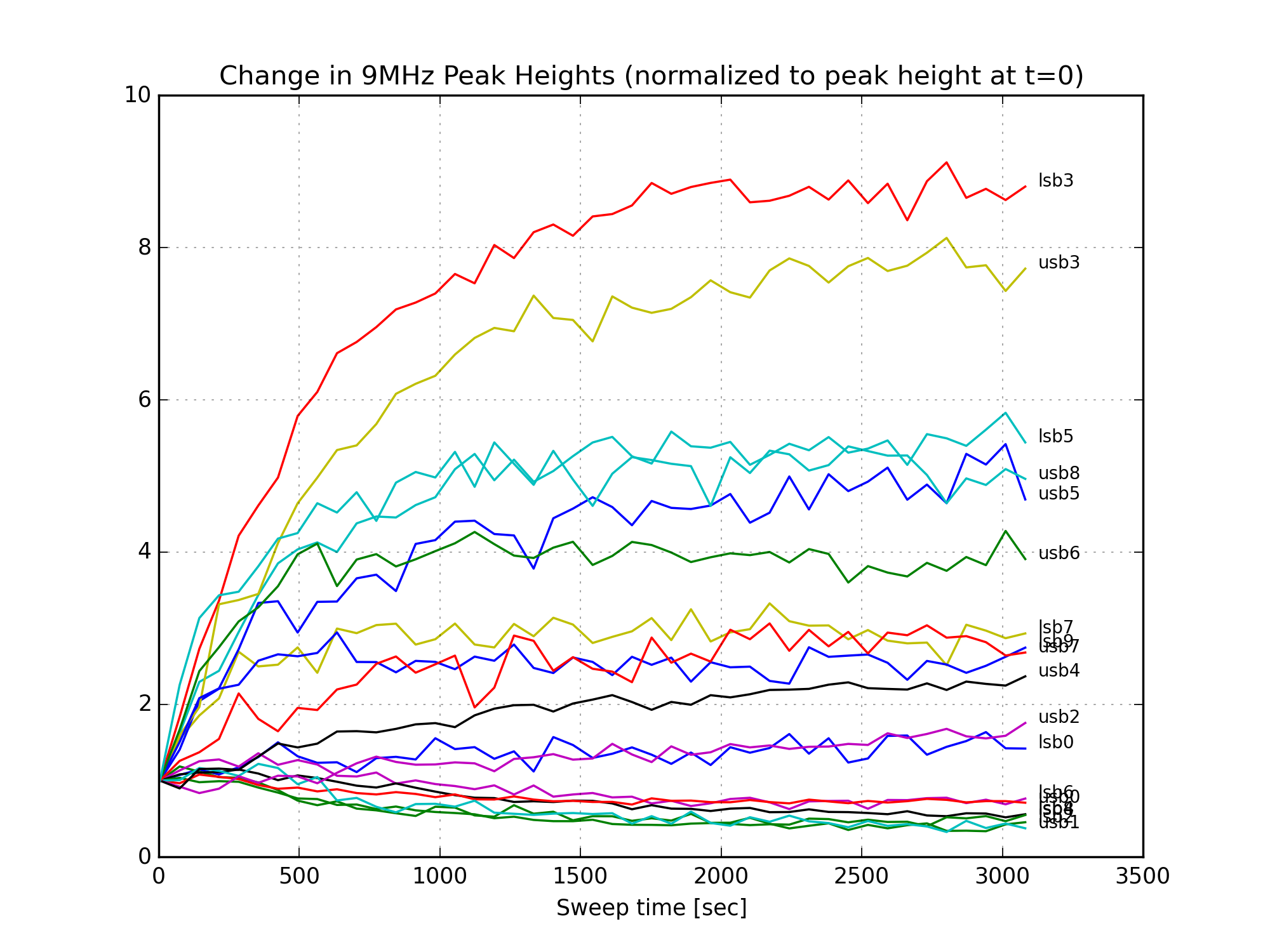
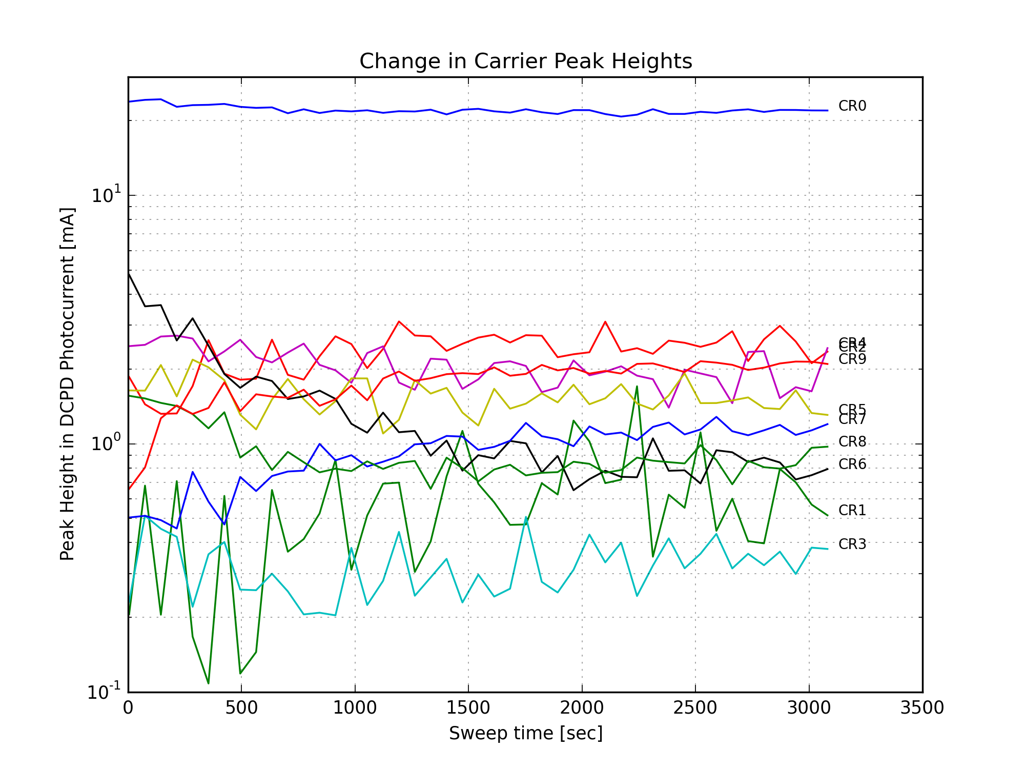
The figures attached are the following:
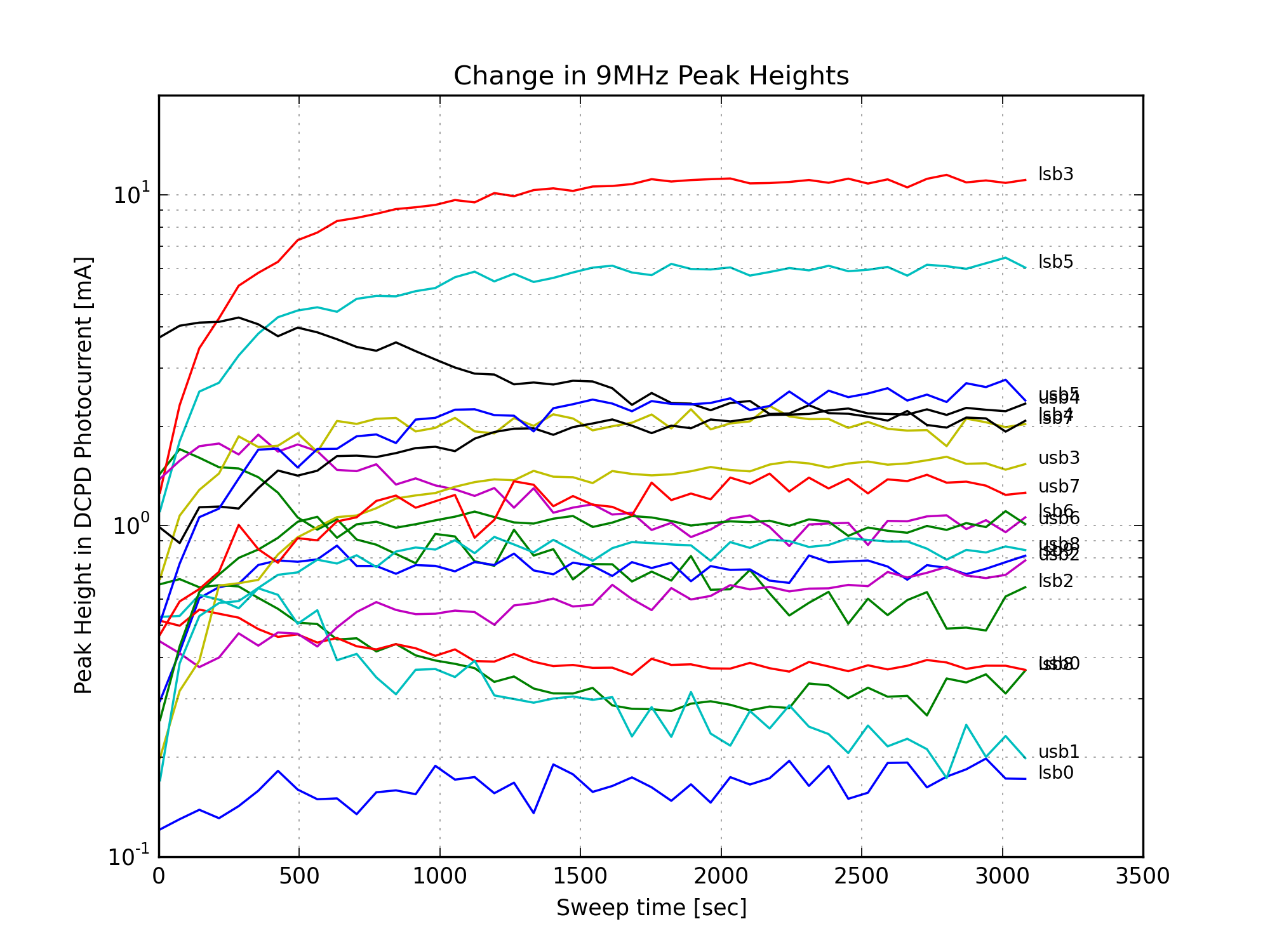
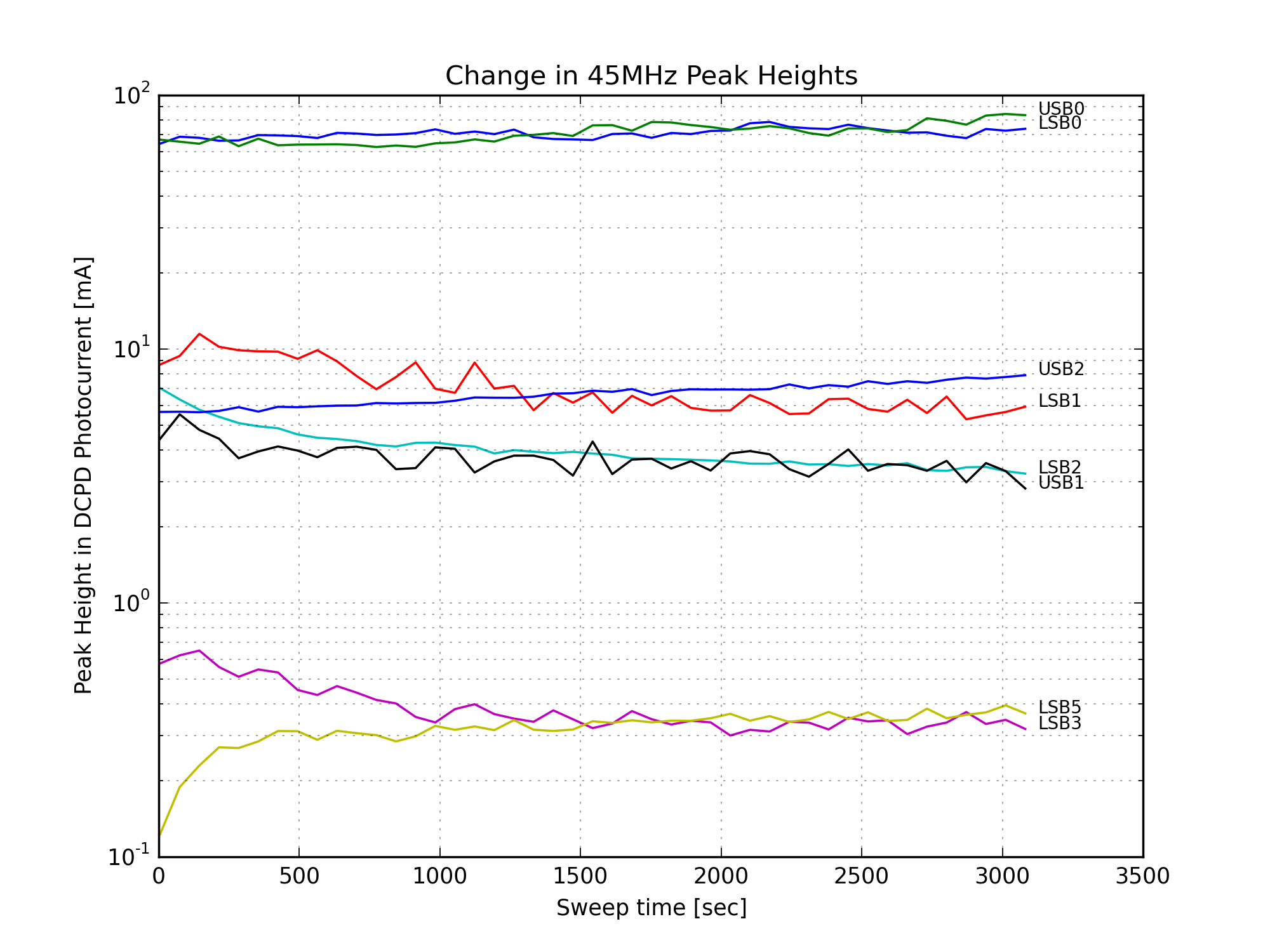
Figure 1 is a GIF movie showing the evolution of the peak heights following the power up. Note the dramatic increase in lsb3, a higher-order mode of the 9MHz lower sideband.
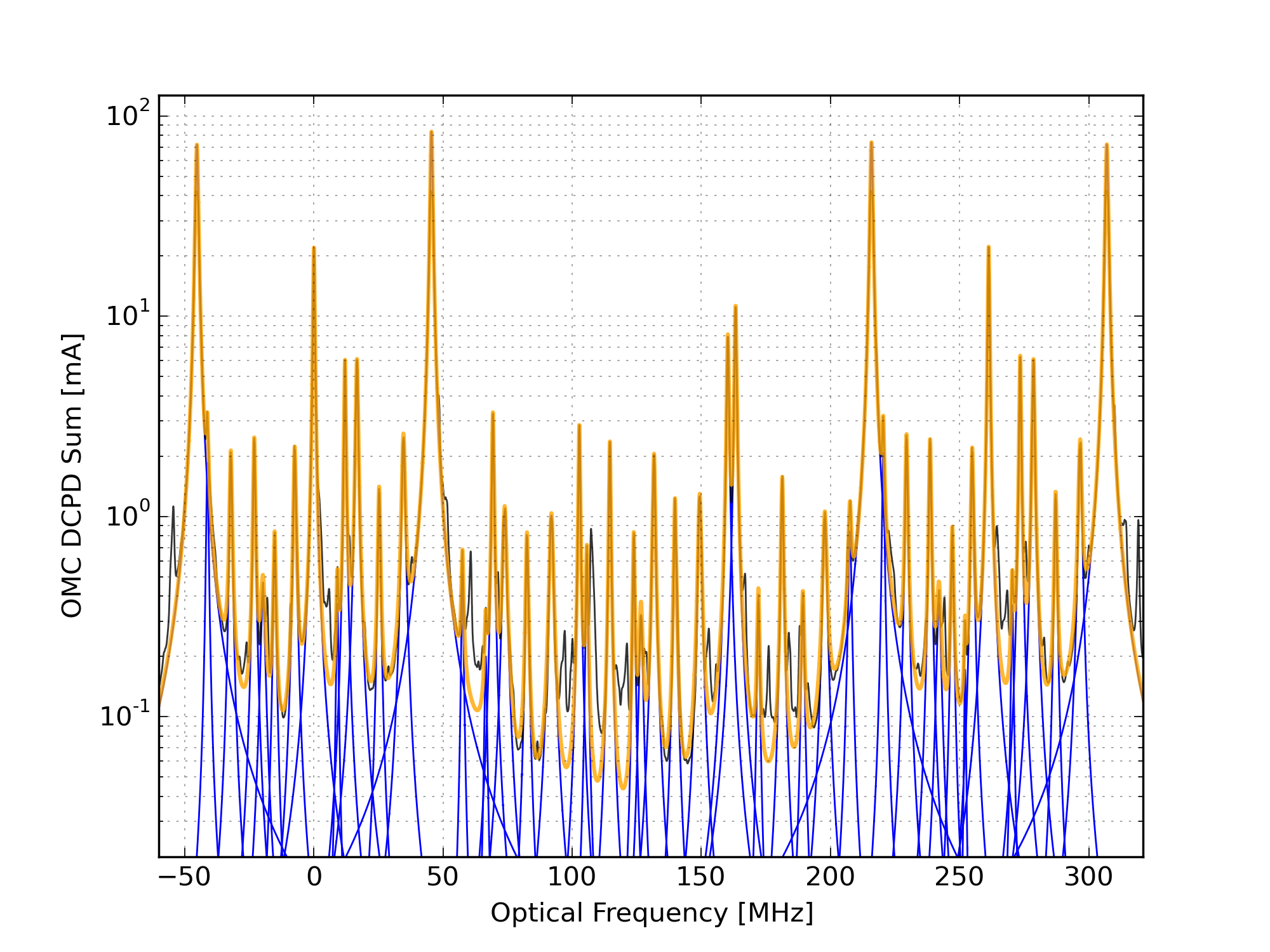
Figure 2 is a GIF demonstrating the peak fitting procedure.
Figure 3 illustrates the saturation of the DCPDs by the 45MHz sideband peaks. The fit to the peaks (which is necessary for the subtraction of the peak shoulders from the surrounding data) is performed using the data on either side of the flat-top from the saturation. To the eye this looks pretty good, but the peak heights from the fit are way less than what we expect, so there's something bogus going on here.
Figure 4 shows the result of the mode fitting (the same data as Fig. 2).
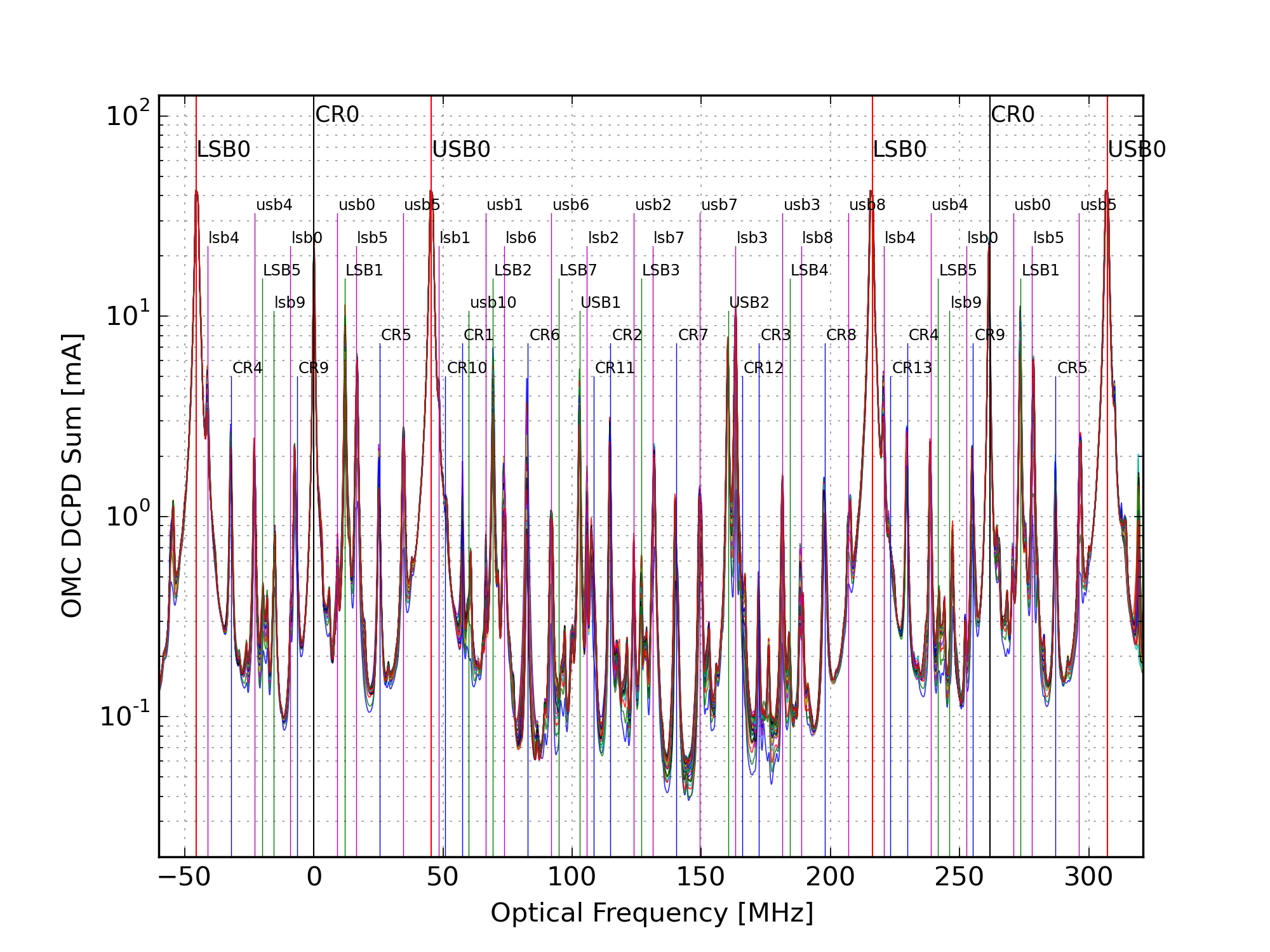
Figure 5 overlays all of the hi-power mode scans and labels the peaks. Not all of the peaks that are labeled are fit in the analysis.
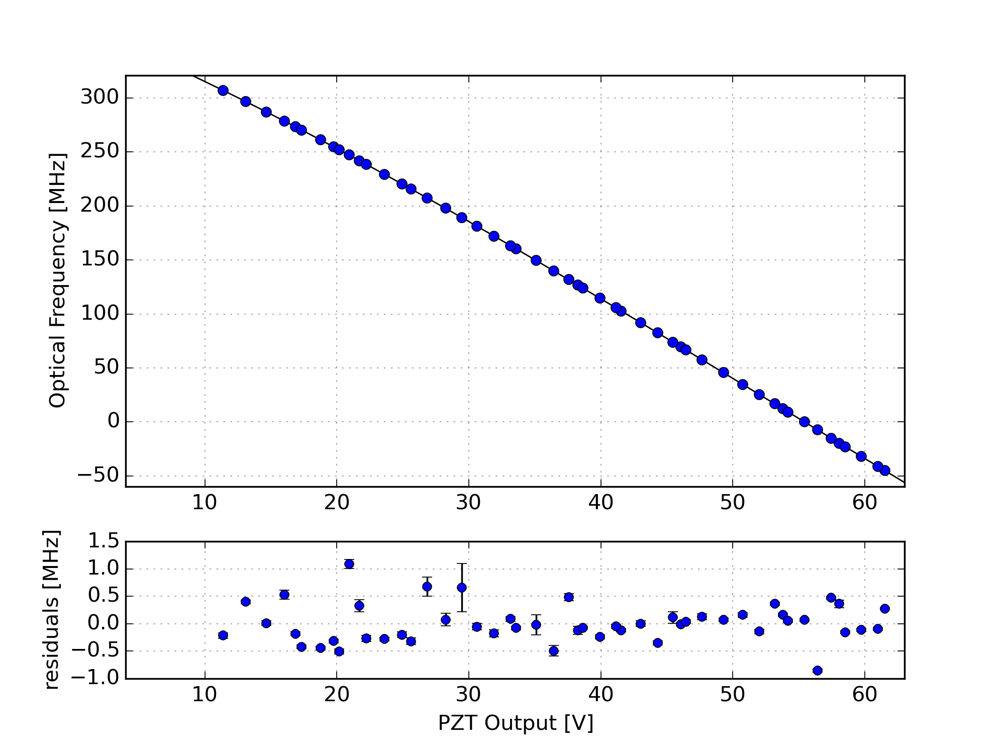
Figure 6 shows the fit of the peak locations (in PZT voltage) to the expected optical frequency, using a 4th-order polynomial fit of voltage to frequency. This is a sanity check that we correctly labeled the peaks. The error bars are the standard deviation of each peak location, across the few dozen mode scans. This is a crude measure of the statistical variation in the peak fitting.
Figure 7 shows the results of the beacon dither demodulation for one sweep. Black is the raw DCPD data, blue is the demodulated data at the frequency of the DARM excitation, and green is the background demodulation. This is a replica of Koji’s plot from April. The blue trace has been multiplied by a constant so it matches the black trace (raw data) at the CR0 peaks.
Figure 8 shows the fraction of each carrier mode that is tagged by the DARM excitation. The fraction of the 00-mode from the arms is unity, by definition. Except for the 01,10 mode (due to misalignment from the QPD servo), most of the carrier HOMs are due to junk light, i.e. the fraction of each mode from light resonant in the arms is small.
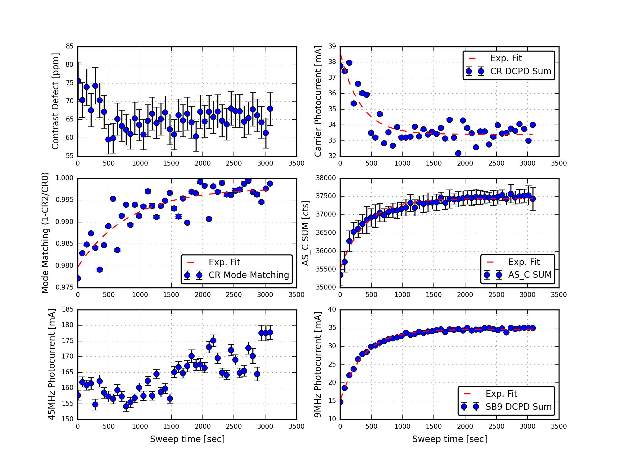
Figure 9 plots various interesting results as a function of time since power-up. This plot is probably the most interesting collection of results. The contrast defect is fairly stable (upper left). Notice how the carrier mode-matching into the OMC improves over time (middle left), and how the 9MHz power increases (lower right). The total photocurrent in the 45MHz sidebands (lower left) is bogus due to the saturated peaks. The time evolution of various measured quantities were fit with exponential curves, the time constants returned by the fits are:
Total photocurrent in 9MHz modes: 370 seconds
AS_C SUM: 400 seconds
Carrier mode-matching (using beacon scan): 830 seconds (note, data are noisy)
Total photocurrent in carrier modes: 320 seconds (note, data are noisy)
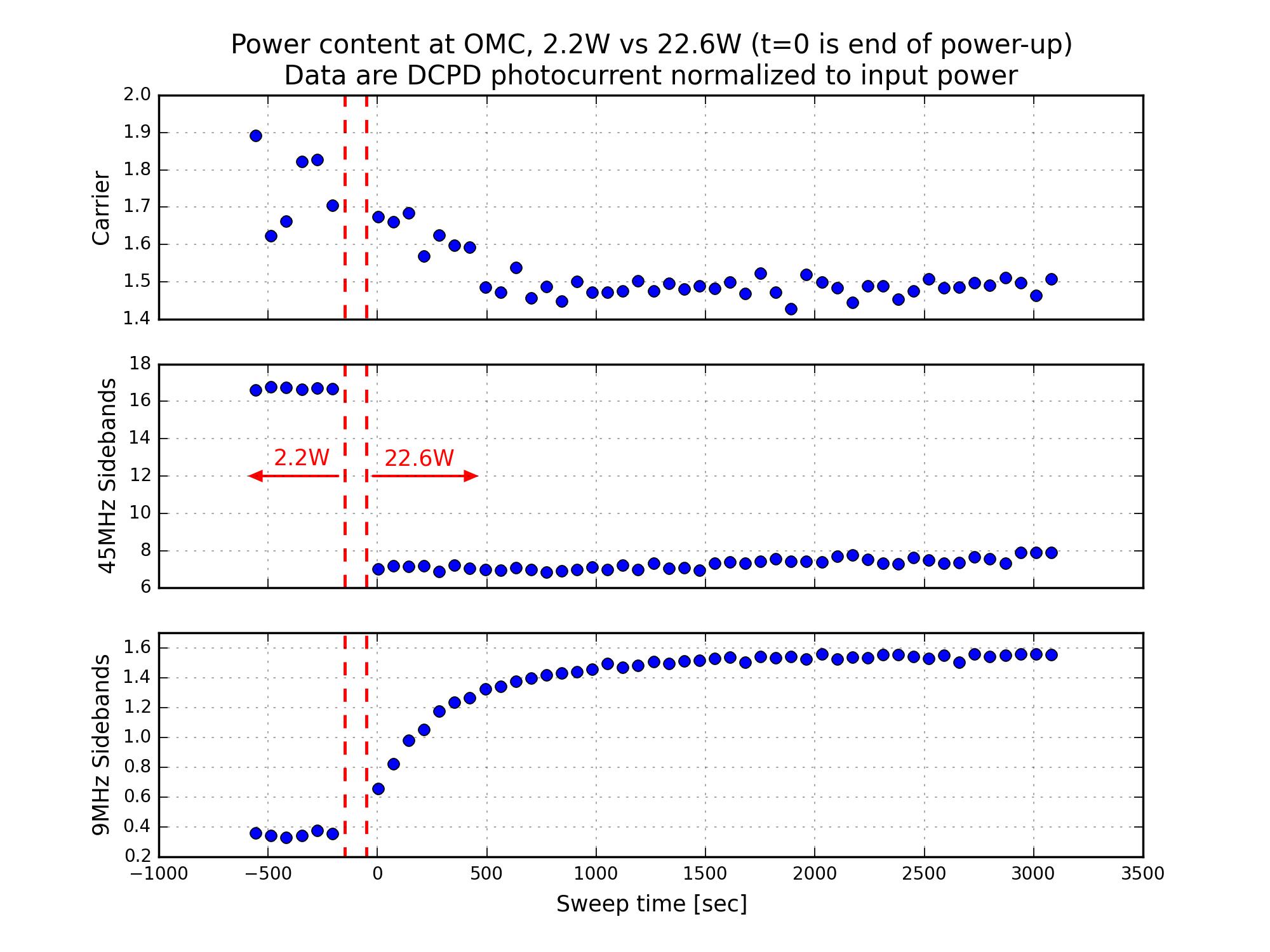
Figure 10 demonstrates the change in power in the carrier, 45MHz, and 9MHz modes around the power-up. Except for the 45MHz data (which is wrong because of the saturated peaks), this is a nice before-and-after picture of the power at the AS port. In this plot, I have normalized the total DCPD photocurrent in [carrier, 9MHz, 45MHz] modes by the input power (measured by IMC-PWR_IN).
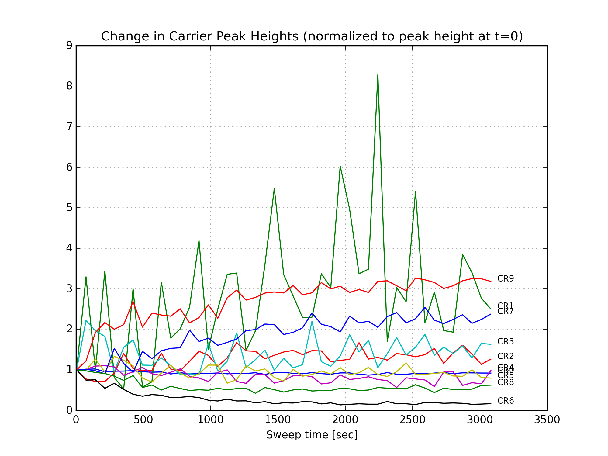
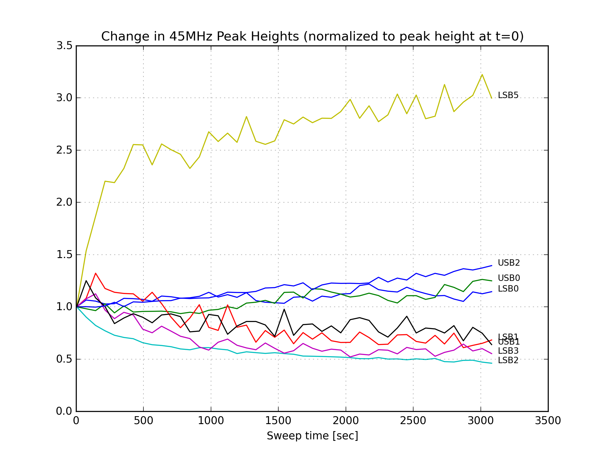
Finally, Figures 11, 12, and 13 show the change in the individual mode heights over time. There is a large increase in the amount of 9MHz HOMs after the power up. (Since the 9MHz light is not well-matched to the OMC, it couples to higher order modes of the cavity.) The 45MHz LSB5 mode increases, but this is a small peak in a fairly noisy part of the mode scan, and might be sensitive to a nearby 9MHz mode. The 6th-order carrier mode loses a lot of power, this is responsible for most of the reduction in carrier power in Fig. 10.
Analysis Code
I have pushed a version of the mode-fitting code to git.ligo.org. This code can’t run on the control room workstations because of the crummy version of scipy that doesn’t have the peak-finding routines, but there is a script included that will download the data with cdsutils, and you can hack away at it on a laptop from there.
Since the beacon dithering required a high sample rate, across one hour of data, most of this analysis was performed on the LHO cluster. The code and results are saved in this directory.
Can you make something like Figure 12 without normalization?
For one thing I'd like to see the ratio of 0 mode VS higher order modes, and for another it seems to me that the SB imbalance is not small for 9MHz at t=4 and becomes worse as time goes, while 45MHz is just fine.
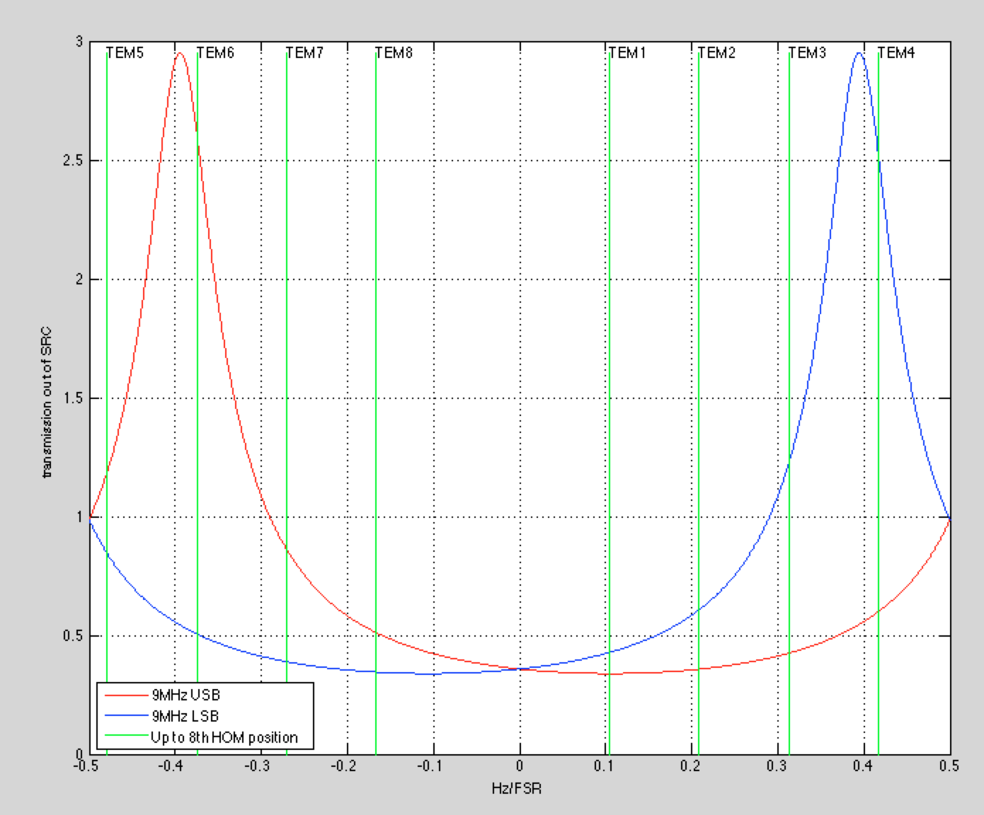
Here are AS LF, 18 MHz, 90 MHz and 36 MHz length signals during the most recent lock stretch. One can clearly see that the 9 MHz is in trouble.
Due to small finesse, only 00 and 1st order mode for 9MHz are anti-resonant. Especially, LSB 4th order HOM as well as USB 6th are very close to resonance.
"Transmissivity" of SRC against LSB4 and USB6 coming out of BS (which is due to differential mismatch from the ITMs or BS lensing) are about a factor of 7 larger than 00 mode.
In this comment I'll try to answer some questions about the calculation details, and post more data on the mode heights.
Parameters for the Contrast Defect Calculation
The contrast defect is calculated as the ratio of junk carrier light at the AS port to the total available carrier light incident on the beam splitter.
Available carrier light on the beam splitter:
P_carrier = p_in * J9^2 * J45^2 * tIO * g_cr = 673 +/- 40 W
Losses between beamsplitter and DCPDs (including photocurrent --> power calibration):
P_loss = tSRM * tOFI * rOM1 * rOM3 * tOMC * PDresp = 0.241 +/- 0.008 A/W
The uncertainties on the parameters above are guesswork, not motivated by any direct measurements. The dominant source of uncertainty turns out to be the recycling gain.
The total photocurrent in carrier HOMs measured by the DCPDs is about 12mA. Of this, about 0.7mA is tagged as good light from the arm cavities. Most of this is due to the CR1 mode -- this is expected, since the OMC alignment is not optimal on the QPD servo. The CR1 mode is quite small, so nearly all of the carrier HOM content is tagged as 'junk light' not resonant in the arms. This is the measurement used to calculate the contrast defect:
P_junk = 11.3 +/- 0.03 mA
contrast defect = P_junk / (P_carrier * P_loss) = 69 +/- 5 ppm
**Note: in the initial calculation I used a recycling gain of 38+/-2. Now I use 36+/-2, this has changed the result from what was presented in the main entry.
Mode Matching Worst-Case
While the calculation of the contrast defect is somewhat immune to mistakes in the beacon scan measurement (since the amount of carrier HOM content is so small to begin with), the calculation of the carrier mode-matching is highly sensitive to systematics in the beacon scan results. As is shown in Fig 8 above, the fraction of the CR2 mode that is tagged as 'good light' starts around 20%, but decreases as the IFO thermalizes to around 2%. If this is incorrect, we have overestimated the mode-matching into the OMC.
To calculate a worst-case scenario, the photocurrent in the CR2 mode for the last 15 mode scans is 2.6 +/- 0.3 mA. The fraction tagged as good light is 0.025 +/- 0.014. The carrier 00-mode photocurrent is 21.7 +/- 0.4 mA. If all of the CR2 light is from the arms, the mode-matching is 88%.
From the mode scans at low power, we know that a substantial amount of CR2 light can be present at the AS port even when the DARM offset is zero, implying the small CR2 fraction from the arms could be real. (Note: I think the low-power mode scans were taken with different TCS settings, certainly different ETM ring-heater settings.)
Mode Height Plots
In the attached plots, I try to answer Keita's question from above. These plots show the mode heights of the carrier, 9MHz, and 45MHz peaks over time, starting at the end of the power-up step. Some things to note:
I also attach two text files. The first has the median measured mode height, in mA of photocurrent, for all the modes fit within a single FSR. The value and uncertainty for each mode are calculated as the median and std() of the mode heights across the last 15 mode scans in the dataset. The final column is the measured frequency of the mode location, based on the fit of PZT voltage to optical frequency. (Remember, we use upper case LSB and USB for the 45MHz sidebands, lower case lsb and usb for the 9MHz sidebands.)
The second text file lists the carrier modes (zero through eight) and the measured fraction of the mode due to the 'good light' resonant in the arms, calculated from the beacon scan. Again, the uncertainty is calculated from the std() of the final 15 mode scans.
Today, I discovered that on all of the HXTX Aux Ch screens (SUS_CUST_HXTX_MONITOR_OVERVIEW.adl) each of the M3 stage indicator lights are COPY/PASTEs of the M2 ones. The channel values are all reading the appropriate channels, but the visual is incorrect for M3. See attached.
Need to fix...
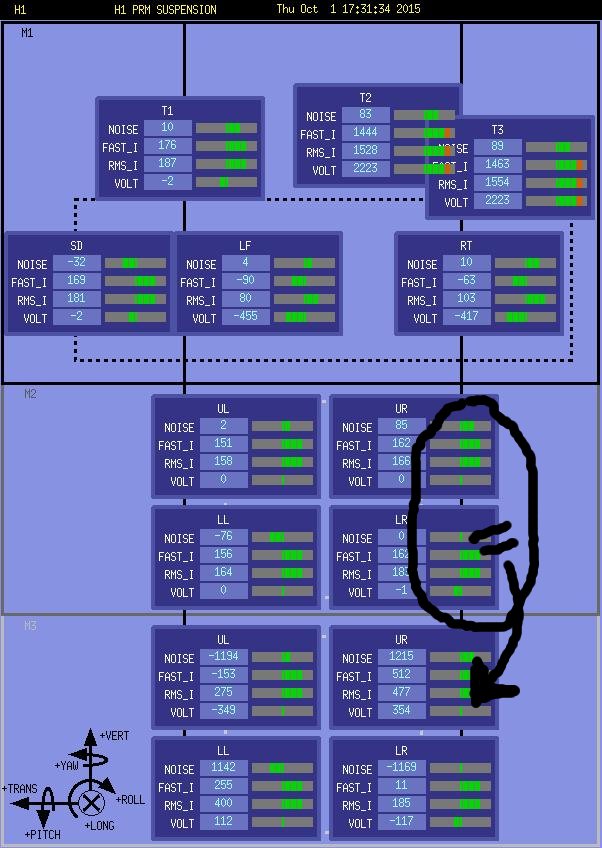
Disregarding my "HXTX" references above which should read "HXTS", I've fixed the error in the screen and committed it to SVN.
Screen address:
/opt/rtcds/userapps/release/sus/common/medm/hxts/SUS_CUST_HXTS_MONITOR_OVERVIEW.adl
Locked in Observing mode for 2.5 hours. Some hardware injections have taken place, but are done for the evening.
I had to restart the graceDB querying between injections. I'm not exactly sure when this failed, but I stumbled across it while doing my usual operator surveys. Had I not had the injection control window open, I would not have known that querying had failed. Perhaps we should put an alarm in Guardian that lets us know querying has failed and needs restarting.
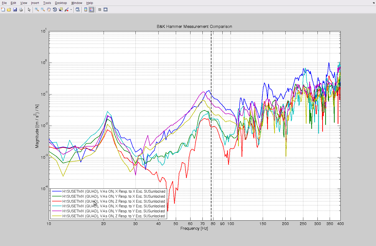
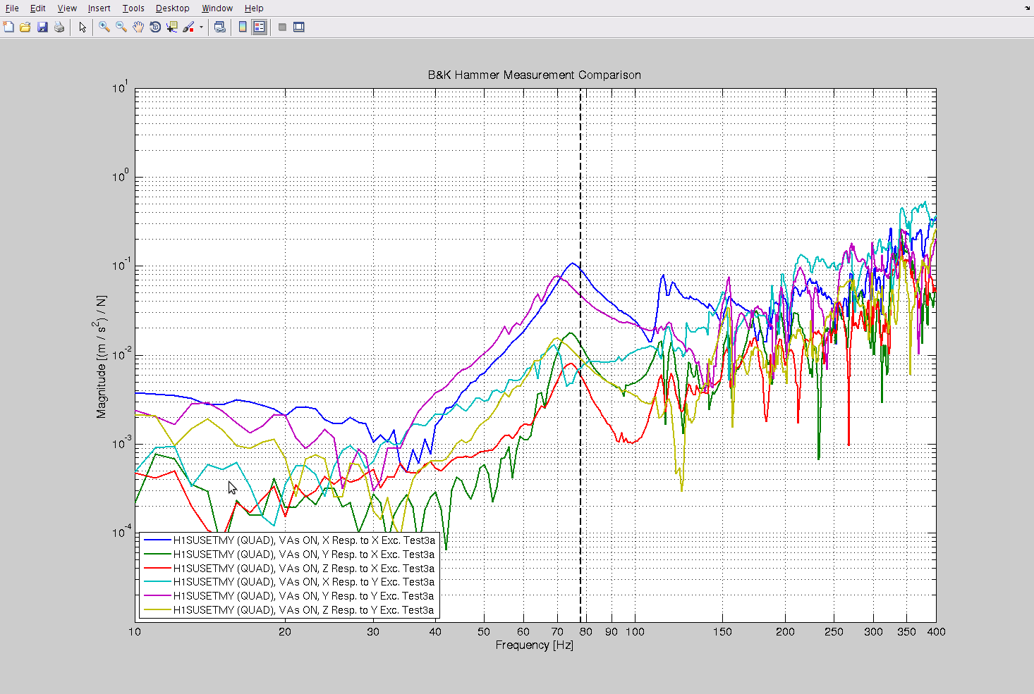
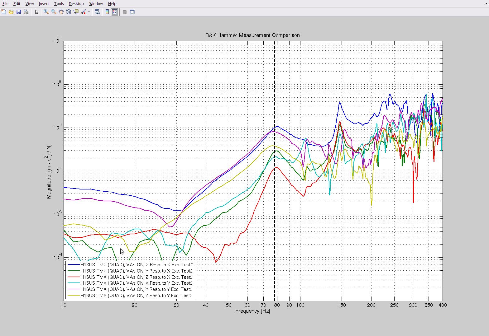
Using a nice plotting script from Stuart (maybe Arnaud?), I was able to plot a bunch of the ITM and ETM BandK hammer data that we took around installation. In all plots, the SUS was unlocked while the ISI's were locked (- it was decided long ago that there was not much change in the QUAD structure plots when comparing ISI locked and unlocked, and I confirmed this in a few cases again today). All data was taken in-chamber in the late stages of the installation.
Attached are plots of each of the 4 H1 QUADs, with a line marking 78Hz for ease of hunting, with the exception of the ITMY plot which has a marker at 75Hz. (The ITMY data was one of the first data sets taken and we did not manage to export it in the same manner as the subsequent measurements so it is posted in the BandK PDF plotting tool, and can't be imported easily into our matlab script. You can evaluate the 78Hz reagion just the same, however.)
In summary - the anticipated ~75Hz structure resonance are shown at:
ETMX 75Hz and lower ~few Hz
ETMY 75Hz and lower ~few Hz
ITMX 75Hz and higher ~few Hz
ITMY 75Hz and lower ~few Hz
I also replotted the ACB and the TMSY (no TMSX data apparently) and do not see anything around 75-78Hz.
Note, the plotting scripts can be found at:
/ligo/svncommon/SusSVN/sus/trunk/Common/MatlabTools/BandK_plot.m
Thanks to Stuart for today's help troubleshooting this.
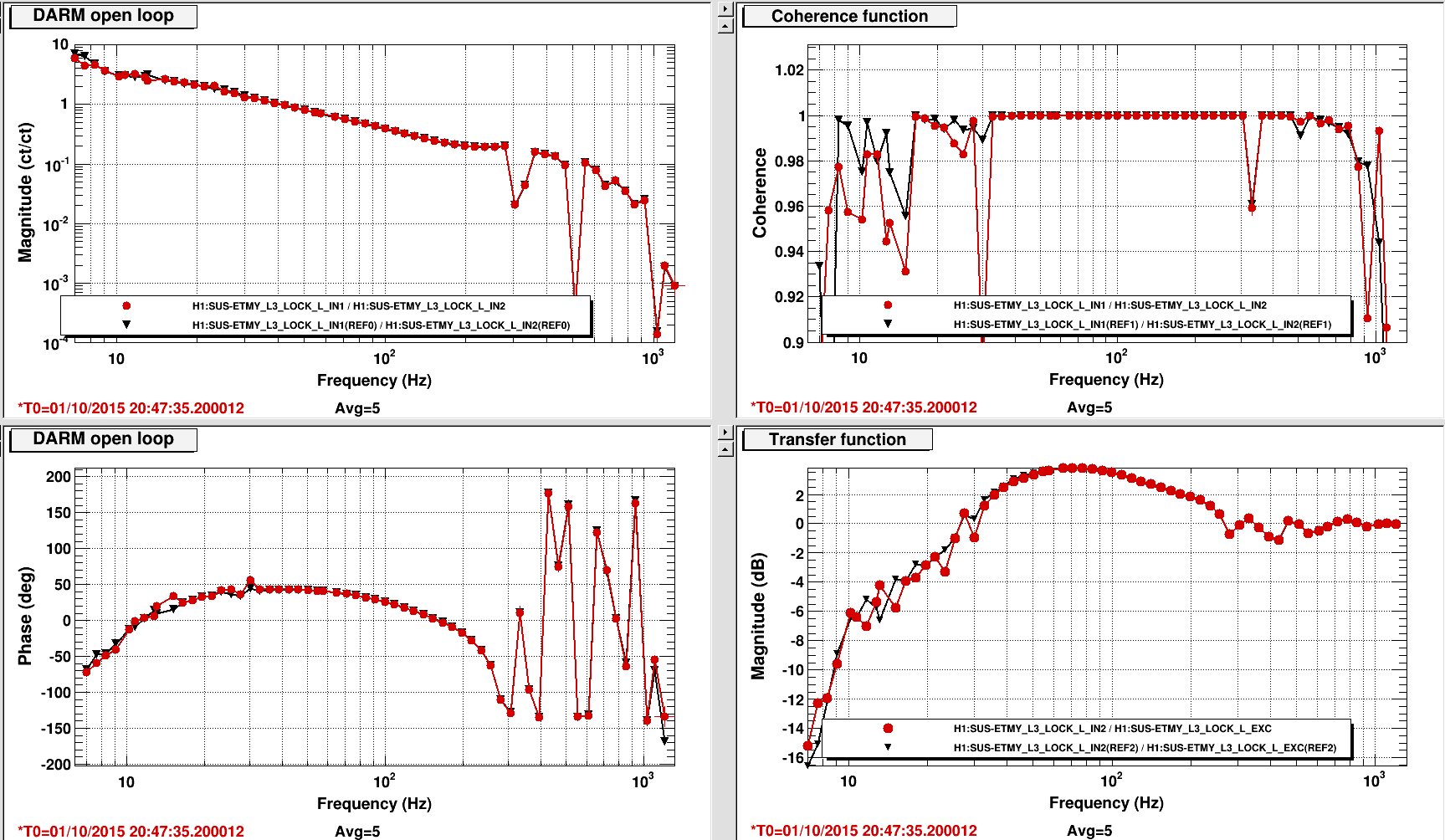
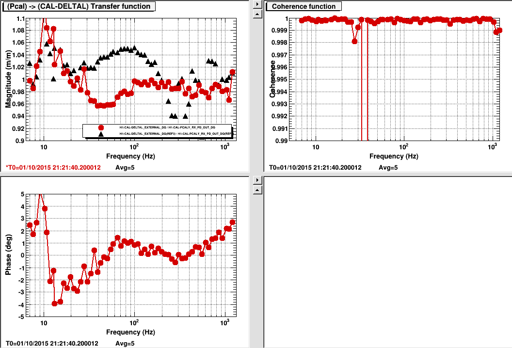
S. Karki, C.Biwer
Used the single IFO time to do the regular DARMOLGTF and PCALY to DARM sweep measurement for regular calibration purpose. We also did a sweep at PCALX and used the measurement to create inverse actuation filter.
The coherence dropped to .95 during PCALY sweep at around 35 Hz because I forgot to turn of the x_ctrl line. Oops!
The measurement files are committed to the SVN:
DARMOLGTF: /ligo/svncommon/CalSVN/aligocalibration/trunk/Runs/O1/H1/Measurements/DARMOLGTFs/2015-10-01_H1_DARM_OLGTF_7to1200Hz.xml
PCALY SWEEP: /ligo/svncommon/CalSVN/aligocalibration/trunk/Runs/O1/H1/Measurements/PCAL/2015-10-01_H1_PCALY2DARMTF_7to1200Hz.xml
PCALX SWEEP: /ligo/svncommon/CalSVN/aligocalibration/trunk/Runs/O1/H1/Measurements/PCAL/2015-10-01_H1_PCALX2DARMTF_7to1200Hz.xml
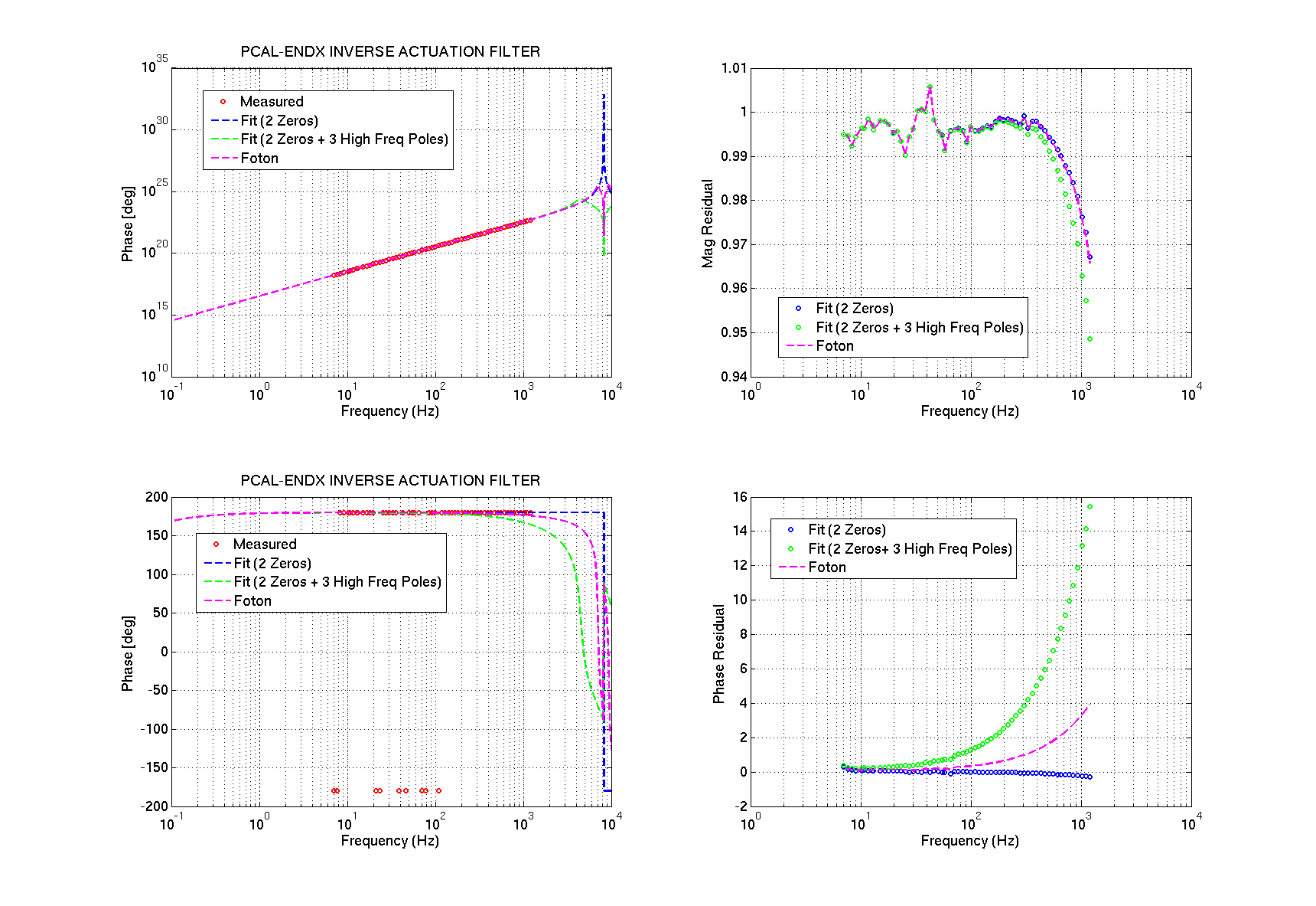
S. Karki, C. Biwer, R. Savage
The factor of two that was missing from the pcal inverse actuation filter installed at X-end is now retrieved from a new transfer function measurement and a appropriate new filter is ready to install. The filters we used previously were created by using the transfer function taken from PCALY. The two Pcal should in principle be very similar and we were working on that principle.
Today in trying to troubleshoot, we took a transfer function between RxPD and EXC at Xend and used it to create the inverse act. filter. We were able to retrieve the missing factor and possibly the sign as well. This still doesnot explain why there is this factor of 2 in the pcal response between the two end. Will continue investigating on it.
The factor of two is not unexpected and should not impact the calibration. We pick off a small part of the laser light that goes to the ETM using an uncoated optic oriented close to Brewster’s angle. The small fraction of the light reflected from this optic (less than 1%) is a strong function of the angle of incidence. The reflected light is directed to the Optical Follower Servo photodetector . The percentage of light reflected, along with attenuators installed in front of the PD, coupled with the diffraction efficiency of the AOM, could easily account for this factor of 2. The excitation signal generates an offset in the Optical Follower Servo that is compared with the light level from the OFS PD. The OFS ensures that they are equal and opposite (in sign). We monitor the actual light that is directed to and reflects from the ETM and the calibration is based on this.
In the meantime, we will install this new filter at the next opportunity and do a test through a full transfer function as well as waveform injection.
Attached is a plot with measured TF and an appropriate fit.
Adam M., Chris B.

We are going to be scheduling coherent hardware injections. Will update with schedule lines.
1127783813 1 1.0 coherentbbh0_1126259455_
1127784860 1 1.0 coherentbbh1_1126259455_
1127785760 1 1.0 coherentbbh2_1126259455_
1127786667 1 1.0 coherentbbh3_1126259455_
1127787567 1 1.0 coherentbbh4_1126259455_
1127788467 1 1.0 coherentbbh5_1126259455_
1127789367 1 1.0 coherentbbh6_1126259455_
1127790274 1 1.0 coherentbbh7_1126259455_
At H1 tinj is being paused and cannot be re-enabled the second injection did go through at L1. We remembered to change CAL-INJ_EXTTRIG_ALERT_TIME. So we are removing injections that would have failed from the schedule.

The schedule now reads:

1127783813 1 1.0 coherentbbh0_1126259455_
1127784860 1 1.0 coherentbbh1_1126259455_
1127789367 1 1.0 coherentbbh6_1126259455_
We are done updating the tinj schedule. After last injection will post aLog with more details.
Argh! The version of ext_alert.py running at LHO is evidently an older version which is still setting H1:CAL-INJ_TINJ_PAUSE in addition to H1:CAL-INJ_EXTTRIG_ALERT_TIME. tinj imposes an automatic 1-hour pause based on H1:CAL-INJ_EXTTRIG_ALERT_TIME; setting H1:CAL-INJ_TINJ_PAUSE is an independent pause mechanism, intended for humans to use. This is the same issue we had for last week's hardware injection tests (alog 21932). It's too bad the software wasn't updated to match the current version which is running at LLO.
Following on from where Hugh left off in alog 21412, I have copied the OBSERVE.snap files from their target area to their appropriate userapps/...h1xxxxx_observe.snap area in prep for committing them to svn. I have copied these files for: SUS, ALS, ISC, CALEX, CALEY. Hugh had already done LSC LSCAUX ASC ASCIMC OMC OAF TCSCS CALCS, and all SEI. The balance (AUX IOP ODC and PEM) have no observe.snap file since it is unneccessary. The ones that I've just copied will be committed to svn tomorrow.
This eve, I finished committing the moved-over OBSERVE.snap files to the svn. I also committed the lsc OBSERVE.snap since we had changed a few settings (DHARD Y FM2 for example) recently.

