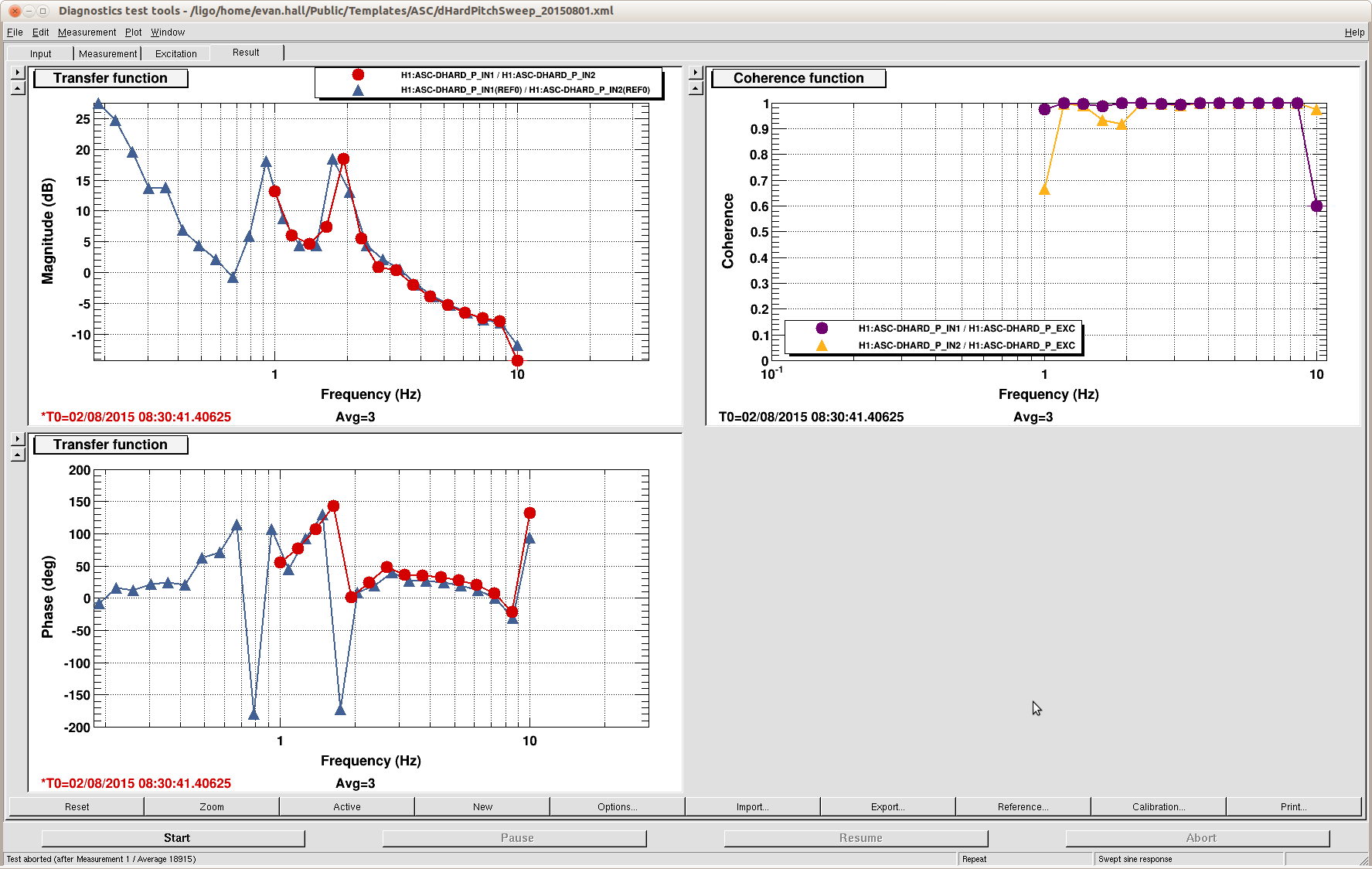
There has been some concern that there might be excess cps noise in some of the channels. So i looked at 20 minutes of data at 1am sunday night/monday morning.
Looking only above 30Hz where the sensors have hit the noise floor, all of the coarse channels are similar and between 3.5-4.5E-10m/rrtHz about what we expect.
The stage 2 channels show two outliers, ITMX H2 and ITMX V1, maybe BS H2 also but that is close enough so that it could just be at a large offset (we expect the noise floor to go as the gap squared) I'll check that.
The first thing to do is for me to look at another time, and to check the cables and connections for those sensors
I looked at a second data set calling it "B" (24 hours later) ST2 ITMX H2 and ST2 ITMX V1 still show excess noise BS H2 is down to 4.5-5E-10m/rtHz which is a little bit noisy, but probably within what we are calling acceptable. I attached the data because Jeff asked to see the ADC noise on the plot
When I say large offset I mean > 10000 counts, so 1200 counts is centered for this discussion
ITMX Stage2 H2 & V1 CPS offsets are 900 & 3800 counts. While V1 is actually the largest offset of all the BSC CPSs, H2 is 21st of 30 (towards the bottom) of Stage2 CPS offsets. At 1200cts, BSC2 H2 ranks 17th of 30. So the offset maybe an issue for ITMX V1 but the others...? And, what about ITMY V1 at 3700 counts and ITMX V3 at 3200?
Attached are all the BSC medms showing the offsets.
Some additional info regarding the CPS - On the figures are plotted time series, integrated RMS, and ASD down to low frequencies. Somme comments:
- At high frequencies, not much to add on sensor noise (ITMX and BS both have two CPS untis with elvevated sensor noise on Stage 2). I looked at data of the Nov 17th, 18th and 19th, and get similar results.
- All Stage 1 CPS units are within 1um p2p, except BS horizontal that is moving 4 times more. Something to look into.
- At the microseism, the three vertical sensors are moving in sync, on all stages of all platforms. Probably normal (the platform is inertially decoupled down to the micro-seism with th 90 mHz blends)
- The low frequency motion amplification is about 100 times larger in the vertical directions than it is in the horizontal directions.
The 5 figures in the previous log are for data ten on the 17th at 3pm PT.
Results and comments are similar for the 18th and 19th, except for ETMX (attached plot) that shows different behavior at low frequencies, as expected with the sensor correction that was turned on Tuesday. It also shows features on Stage 2 at the SUS resonances, that might need to be doubled checks.
Could this be related to the trips on ITMX? (alog 15021)
this log seems to have gotten hijacked
I check the HAM-CPS and they all seem to be good at high frequency
In a previous report I showed that the beam can wander on the IMC WFS by something like 0.1 in QPD normalized units. To understand how much this can affect the optimality of the IMC alignment, I moved the beam on WFS using the picomotors, and tracked the change of jitter to RIN coupling.
I injected a 11 Hz pitch line on the PZT (amplitude 0.5) and a 17 Hz yaw line on the PZT (amplitude 2) and looked at the amplitude of induced RIN, both in the second loop signals and in IM4_TRANS. All signals gave consistent result, so here I'm quoting only one value.
Here are the raw results. The first four columns give the deviation of the beam position with respect to the initial one (which was not centered)
WFS A pitch | WFS A yaw | WFS B pitch | WFS B yaw | 11 Hz (pitch) RIN x1e-6 [1/rHz] | 17 Hz (yaw) RIN x1e-6 [1/rHz] |
---|---|---|---|---|---|
0 | 0 | 0 | 0 | 8 | 8 |
+0.1 | 0 | 0 | 0 | 6 | 13 |
0 | -0.1 | 0 | 0 | 10 | 8 |
0 | 0 | +0.1 | 0 | 5 | 24 |
0 | 0 | 0 | +0.1 | 8 | 8 |
The effect is not so small, in particular a pitch miscentering of the beam can increase by as much as a factor 3 the coupling of jitter to RIN.
So it seems that the normal wandering of the beam on the long period can give some IMC misalignment that will cause a significant worsening of intensity noise. One solution would be to implement the beam size modification already done at Livingston.
re 15131, attached are pdfs of spectra for the ITMY HEPI L4Cs around 1am Tuesday and Wednesday before and after I made these changes Tuesday morning. The first two pages are the individual runs and the third crowds things up and puts them on the same plot to maybe improve the comparison.
Bottom line--some places better some not as good even considering the differing ground motion. I think these controller could be more aggressive if we want.
apologies for not being more clear o which is which. The earlier time, gps 11003xxxxxx is before 11004xxxxxx is after. On the busy third plot, the first ground and first L4C races are the early time (before) and the second ground and L4C traces are at the later time, after the change.
model restarts logged for Tue 18/Nov/2014
2014_11_18 01:41 h1fw0
2014_11_18 10:51 h1isiham4
2014_11_18 10:51 h1isiham5
2014_11_18 10:56 h1sussr2
2014_11_18 10:58 h1sussr3
2014_11_18 10:58 h1sussrm
2014_11_18 11:01 h1hpiitmy
2014_11_18 11:27 h1broadcast0
2014_11_18 11:27 h1dc0
2014_11_18 11:27 h1fw1
2014_11_18 11:27 h1nds0
2014_11_18 11:27 h1nds1
2014_11_18 11:29 h1fw0
2014_11_18 11:54 h1psliss
2014_11_18 11:57 h1broadcast0
2014_11_18 11:57 h1dc0
2014_11_18 11:57 h1fw0
2014_11_18 11:57 h1fw1
2014_11_18 11:57 h1nds0
2014_11_18 11:57 h1nds1
2014_11_18 11:58 h1nds1
one unexpected restart. Maintenance day. Ham4,5 ISI and SUS work, with associated DAQ restart. PSL ISS work with associated DAQ restart. Double restart of h1nds1?
Alexa, Dan, Nic, Sheila, Evan
Tonight we made some improvements to our automation, and we reduced the CARM offset with DRMI locked on 3F.
I have attached DRMI spectra on 1f and 3f with the arms off resonance (1kHz green COMM offset). The first plot is the DRMI 1f configuration; Kiwamu pointed out that one can see the periscope resonances that are present in ALS COMM noise appear in the DRMI signals. The second attachment is of the DRMI 3f configuration, and these noise features are less prominent.
Relevant UTC times:
Great progress! About the ASC, L1 uses REFL_B_45Q -> SRM with bandwidth of 100 mHz ( LLO 13513 ) in the first part of the locking sequence, as AS_RF36_I for SRM didn't work well ( LL0 13358 ). Here I see that you are using AS_RF36_I for SRM ASC in DRMI without arms...just checking.
Thanks for the information Lisa.
Also, for the record, here are several times that we lost the arm locks last night without a known reason (at least, we didn't think we were doing anything stupid at the time that would have caused the lock loss). All times are UTC, Nov 19, and the lock loss should be several seconds before the time I wrote down.
2:36:27, 3:06:34, 5:58:43, 6:12, 6:25:08, 6:51:07, 7:40:50
Here is the sensing matrix of DRMI3f with 7 nm (= 1000 Hzgreen) CARM offset. I extracted this using the three calibration lines that were injected during the locking period: 131.7 Hz, 6000 ct into PR2; 183.7 Hz, 1000 ct into BS; and 152.9 Hz, 6000 ct into SR2.
In the following table, the first number in each pair is the magnitude (in ct/ct), and the second is the phase.
PR2 | BS | SR2 | |
---|---|---|---|
RF27 | 7.6(1.2), 3.4(3)° | 0.29(6), 151.3(7.8)° | 0.07(3), -70(110)° |
RF135 | 12.3(2.0), 139.7(4.5)° | 0.7(3), -84(35)° | 1.6(4), 6(14)° |
J. Kissel Interested to see how the projected ISI channels compared with Kiwamu's assessment of PR3 (see LHO aLOG 15048), I've plotted (a) The input noise budget for the Suspension Point Longitudinal Motion, and (b) The Transfer function between suspension point and L, P and Y of the optic using whatever local sensor was available. for SRM, SR2, and SR3. Remember that the damping loops for these suspensions is still the "hand-tuned" dumb velocity damping. Also note that SR3, Oplev to M2 Pitch damping is ON for this measurement. A couple of conclusions: From the Susp. Point L budget -- (1) For all three SUS, with the current HAM ISI blend design, we're limited by the HAM4 / HAM5 Y motion at just about all frequencies. Where there has been effort to carve out performance at 1-2 [Hz] in Y in the ISI, RX of the ISI limits the performance. (2) Some how, even though RZ appears WELL below the limiting noise source for L, it's still somehow ~70 to 80% coherent between 0.1 and 0.6 [Hz]. Huh?? From the Susp. Point L to Optic TFs -- (4) Susp. Point Longitudinal is the dominant contributor to Pitch at the optic, by a long shot. (5) The OSEMs, which are relative motion sensors between the cage and suspension, fall off in response below the SUS's first resonance as 1/f^2 as expected. (6) Perhaps unexpectedly, the OSEMs are still *coherent* below the first SUS resonance, down to quite low frequencies. (7) Susp. Point L, some how contributes a great deal of motion to Yaw as well as Pitch between 0.7 [Hz] and 1.5 [Hz], amplifying input motion as much as a factor of ~100. (8) The difference in damping between SRM and SR2 seems to have significant affect on the Susp. L to Optic L TF at the first and second resonances (0.7 [Hz] and 1.53 [Hz] for the HSTS). Recall that for angle, SR3 contributes the most to *cavity* angular fluctuations.
K. Venkateswara
After the problems with BRS last week (15005), it was left off for the last ~five days. I tested the damper controller and it looked like the issue with vibration driving the BRS had cropped up again (14596). It wasn't clear why this problem had reappeared but since the foam sheet had worked previously, I went back to that configuration. With the foam sheet under it, the damper appears to be working fine. However another issue with it is that the zero position of the turn-table appears to change, seemingly randomly. It is possible that the stepper motor is occasionally getting stuck. As it's not servo'd this may explain the drift in the zero position. For the moment, I think it requires periodic checking to ensure its zero hasn't changed too much. If it changes by 90 degrees, it can drive the BRS in a positive feedback loop like last week. A servo loop is a better long term solution.
I have also modified the following filters:
1. BRS transfer function inversion filter to correctly account for the imaginary zero at 7.3 mHz (due to the finite d). I was using pairQ(7.3e-3,3) before whereas pair(7.3e-3,0) should be the right choice.
2. The tilt-subtraction filter has also been changed - the high-pass filter (2-pole) has been changed from 2.5 mhz to 4.3 mHz to correctly compensate for the T240 resonance.
The attached pdfs show the ASD for the BRS and the ground T240 in angle and displacement.
J. Warner, J. Kissel, K. Venkateswara
After improved modelling of sensor correction (SC), thanks to Rich M. (615, 623), we re-attempted SC along X (and along Z). X sensor correction was to stage 1 ISI, while Z was on HEPI. Unlike our previous attempt (14896), we used Rich's SC_filter described previously in 14570.
The first pdf shows the ASD from before SC for X and Z. Stage 1 T240, CPS and ground motion is shown and the coherence between them. The second shows the platform motions after SC. The third pdf shows a comparison between the configurations as measured by the T240 showing the expected 2-5 factor improvement between 0.1 to 0.5 Hz. It also shows an improvement below that which is more surprising (maybe from Z SC?). There is no visible re-injection of noise (factor of ~2 is epxected between 20-40 mHz), because we are probably dominated by pre-existing noise which is larger. More testing will be done tomorrow. The OpLevs are currently mis-aligned so I can't see the effect of SC on them.
Note that the we did not use tilt-subtraction at the moment because wind-speeds were practically zero. We will test the tilt-subtraction when winds pick up a bit.
Once again, if this appears to be adding noise instead of helping, the comissioners can turn it off from the ETMX ISI medm screen as before.
Looks like the X arm is better behaved this time. I've attached ASD of the ALS-X control signal and the Stage 1 CPSs for ETMX and ITMX from tonight's locking.
This morning, I tried using the tilt-subtracted ground super-sensor for sensor correction along X, rather than the plain ground sensor. The attached pdf shows the Ground Sensor (T240), the super-sensor, Stage 1 T240 X, BRS RY OUT * g/w^2 and the Stage 1 CPS. Please note that the CPS data is after the sensor correction (it is input to the blend filters), hence it is should be less than the ground motion above ~100 mHz.
The plot shows that in non-windy periods, the super-sensor is not much noisier than the regular ground sensor and tilt-subtracted sensor correction is therefore about the same as regular sensor correction.
Gabriele, Jeff, Dave
Two sets of DAQ restarts today:
11:27 Resync INI files for SUS changes made by Jeff (HAM4,5)
11:57 Resync INI file for h1psliss model change, made by Gabriele
No Beckhoff INI changes seen over the past week.
Jamie, Dave [WP4947]
Today we reconfigured and restarted all the guardians to ensure that no log files will be deleted.
The process involved running guardctrl create --all
and then stopping and restarting the entire guardian supervision. The guardian nodes did not restart, which Jamie tracked down to default settings after the re-creation. He started all the nodes, but one of the 71 nodes did not restart cleanly (SUS_MC2). A subsequent restart of this node was successful, Jamie is investigating why this happened.
We will most probably reboot the guardian machine next week for OS security patching and at that time check for any node failing to start correctly. Today we just patched bash
.
We will keep WP 4947 open to cover next weeks patching.
Patrick, Dave
The conlog reporting of frequently changing EPICS channels has discovered several code issues in the past week. Conlog reports hourly those channels which have logged 500 or more changes in the previous hour. I have written a python script to concatinate 24 hourly reports into a daily report, which I'll post in the alog.
Below is the log from yesterday (Monday 11/17). We discovered a guardian node which was setting the end station SUS L1_LOCK_L filters RSET (clearing history) at 16Hz. This was fixed between 1pm and 2pm.
The per-second number is calculated as total/(hours-active * 3600). Numbers in the 16 range are most probably front end or guardian related, higher than 16 most probably Beckhoff or scripts.
11/17/2014 hs total per-sec
H1:SUS-ETMX_L1_LOCK_L_RSET 14 751286 14.9
H1:SUS-ETMY_L1_LOCK_L_RSET 14 751286 14.9
H1:ALS-C_COMM_VCO_TUNEOFS 02 90021 12.5
H1:ALS-Y_FIBR_LOCK_TEMPERATURECONTROLS_ON 06 62062 2.9
H1:ALS-Y_CAM_ITM_PIT_POS 24 58548 0.7
H1:ALS-Y_CAM_ITM_YAW_POS 24 58548 0.7
H1:ALS-Y_CAM_ITM_SUM 24 58539 0.7
H1:GRD-ALS_YARM_USERMSG 05 16658 0.9
H1:ALS-X_REFL_SERVO_IN1EN 05 11208 0.6
H1:SUS-IM4_M1_OPTICALIGN_Y_OFFSET 03 6052 0.6
H1:SUS-IM4_M1_OPTICALIGN_P_OFFSET 02 3136 0.4
H1:GRD-ALS_XARM_STATUS 02 3082 0.4
H1:GRD-ALS_COMM_USERMSG 03 1781 0.2
H1:SYS-MOTION_C_PICO_A_CURRENT_DRIVE 02 1516 0.2
H1:GRD-ALS_XARM_TARGET_S 01 632 0.2
H1:GRD-ALS_XARM_STATE_S 01 550 0.2
H1:SUS-PRM_M1_OPTICALIGN_P_OFFSET 01 504 0.1
Some of the GRD channel changes are likely reflective of actual changes in the system. It's not clear to me that conlog should be monitoring the following guardian channels:
_STATUS _GRDMSG _USERMSG _NOTIFICATION _STATE_S _STATE_N _TARGET_S _TARGET_N _OK
None of those channels are set by users, so they may change as fast as the system changes.
Here is an informational post on a cool tool that I’ve found.
The tool is called Markdown here. It is a way to use a common rich text markup language and use it to make rich text in many web forms. It is (mostly) compatible with the LIGO a-log.
The steps to use it are:
Some of the features that you can use are:
It will accept latex formulae:
class INIT(GuardState):
request = True
def main(self):
log("initializing subordinate nodes...")
nodes.set_managed()
def run(self):
return True
optic | bias | how i feel |
---|---|---|
ETMX | 400cts |
|
PR2 | 5cts |
|
ITMY | 100V | tired |
As you are making your post, you will want to preview what it looks like, but if you want to edit, you must always change back to plain text before you edit, or you may lose changes.
By default, the return
key in the alog makes a double line break. Markdown here works a lot better with single line breaks. You can make single line breaks with shift+return
.
Because most browsers can’t display math fonts by default, the latex formulae are actually images, which is a bit inelegant, but it works. You must also explicitly enable latex formulae in the settings before it will work.
As a bonus, you can also use it with gmail (and thunderbird)! So you can put math in your emails as well.
Good luck!
WARNING: equations in markdown actually utilize a (possibly deprecated!?) online service. This means that the produced equations are actually links to images hosted on a third-party web site. If that site goes away, so do the equation images. Your log post my not look as intended in that eventuality.
Here is a collection of suspicious CPS trips on ITMX. This is a problem only on this chamber, which has just cropped up in the last few weeks. It needs to be investigated.
another example
Still there, still a problem....
I made a few plots today. The spectrum of the CPS right before and right after the trip, and the zoom-in time series plot around the time of the trip. I notice that the time that the CPS signal goes down does not match the GPS time indicated the trip exactly (off by a few hundred milliseconds). While making the spectrum I also notice the peak near 4Hz in the "beforetrips" spectrum plot. So I went and look at the LHO summary page and found that there's a small gaussian-looking bump around 4Hz that seems to appear everyday. Probably not very important but just wanted to point that out. Also, please note that V2, H2, and H1 signals are almost perfectly overlapped (that's why you only see two colors). I'll start looking into other related channels that *should* have seen the signals. Although I believe this might be an electronics issue.