Following the work done last week (see this alog), I've done some more tests today.
First the unsuccessful results:
- I've switched from a lvl3 conroller configuration to a lvl2 with no success. The issue doesn't come from the control loops.
- I turned OFF all the damping loops of suspensions (MC2 and PR2). This didn't affect at all the amplitude of the peaks: the suspensions behavior seems unrelated with our issue.
Now the good part:
The problem seems directly correlated with the blends, and especially with the blends on RX and RY. I'm making this affirmation because of 2 things:
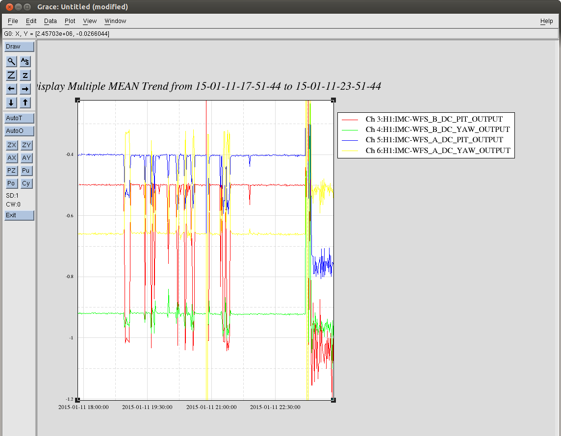
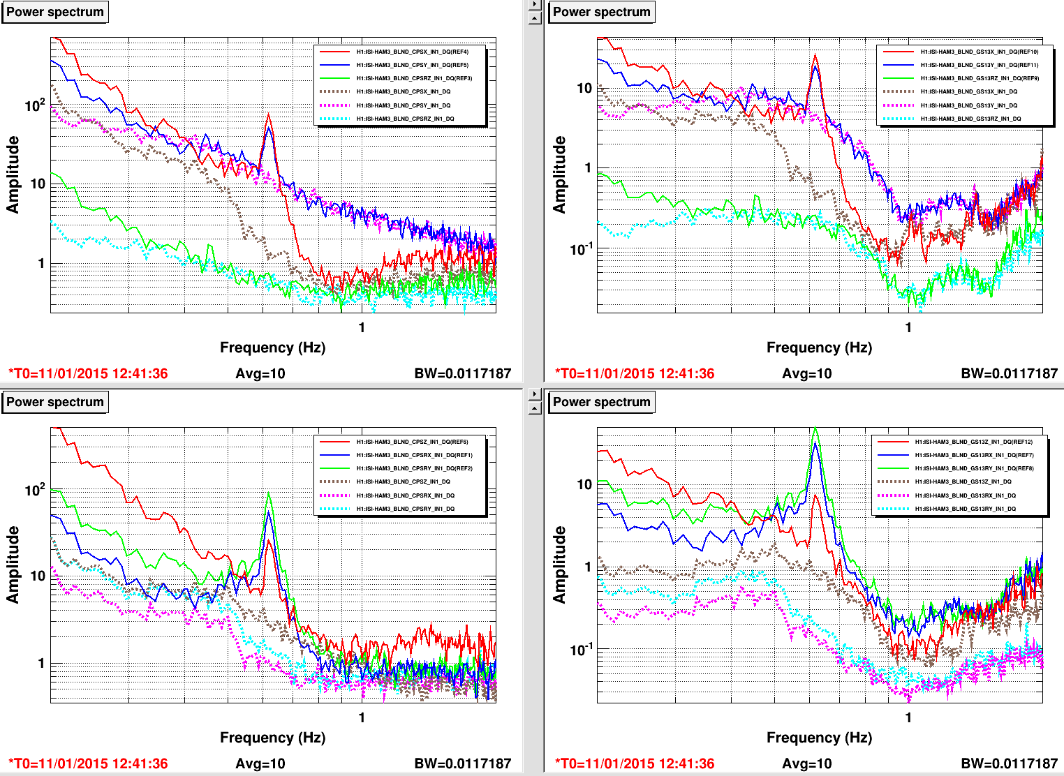
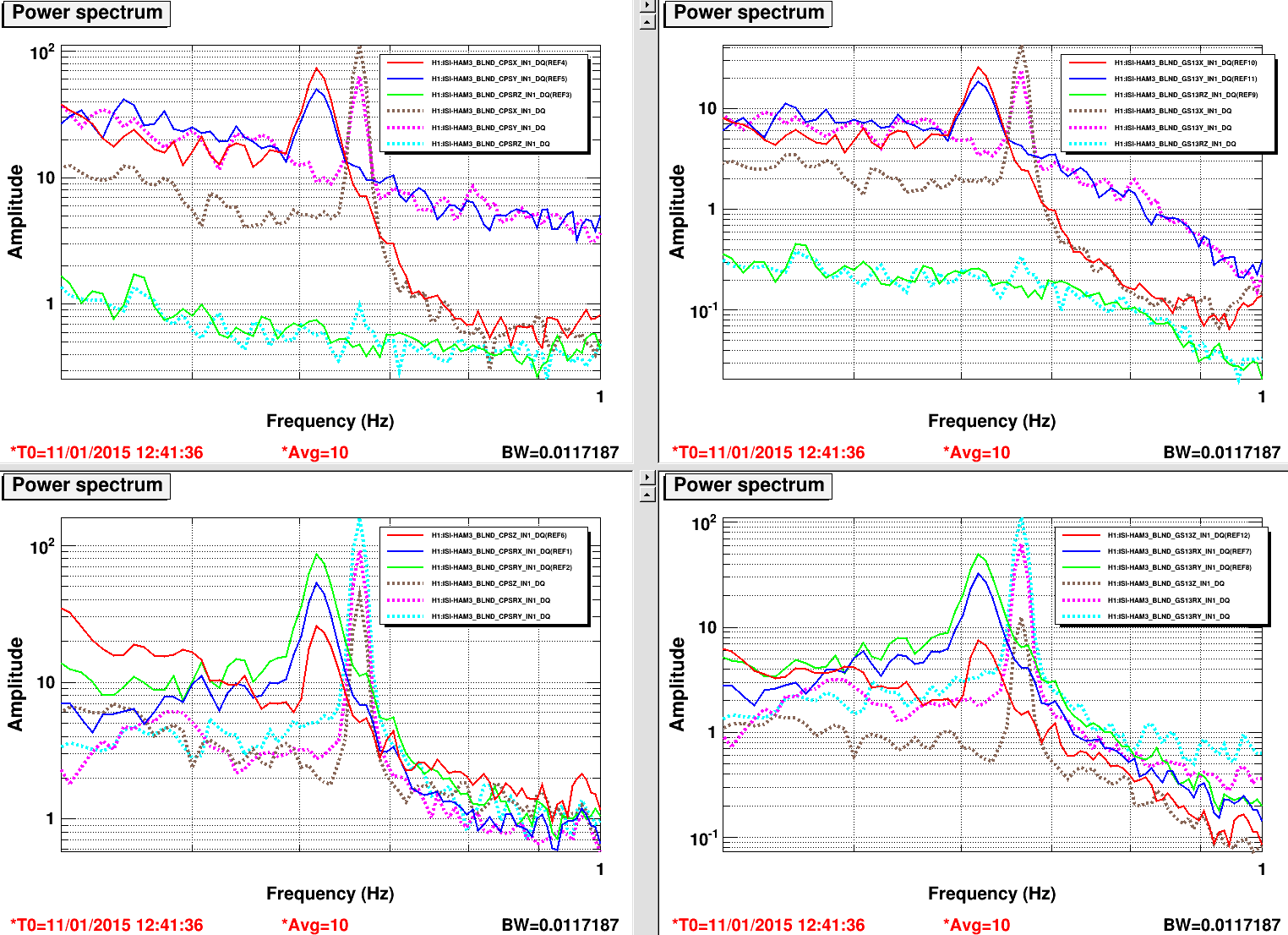
1. The peak disappears when I switch the blends on RX and RY. It stays up otherwise. In the plot atrached, I've switched from a 01_28 blend (solid lines) to a 100mHz blend (dash lines) on RX & RY and the peaks are totally gone. This is true if I switch tfrom 01_28 to another set of blends as well, I took 100mHz as an example.
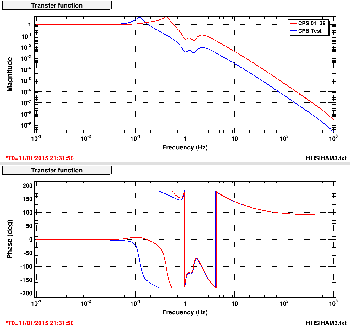
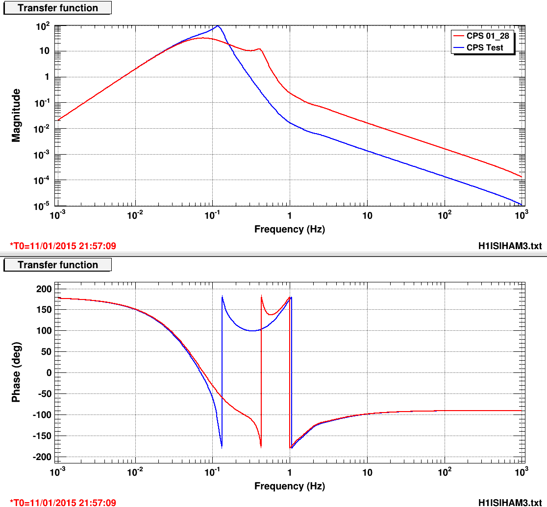
2. I've installed a set of blend filters on RX and RY called 01_28t. They are very similar to the 01_28 blends, I just moved poles and zeros around to see if it makes any difference. It does: the frequency of the peaks shifted from 0.617Hz to 0.664Hz (see plots attached).
Conclusion: We are using this 01_28 set of blends on all the units without any problem: only HAM3 seems to present this bizarre behavior... But even if I still don't understand what's happening, we have a solution. The 100mHz blends are not ideal for these DOFs, and I'll design a better set of blends ASAP.
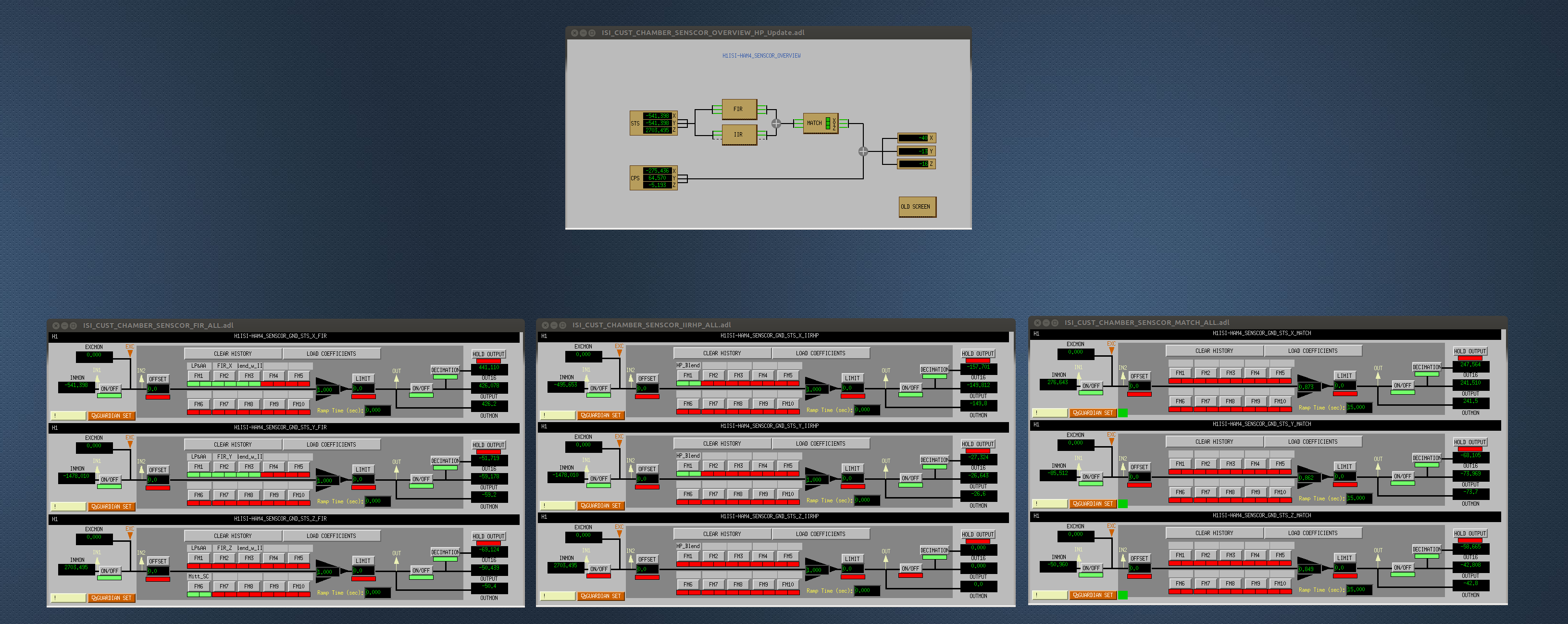
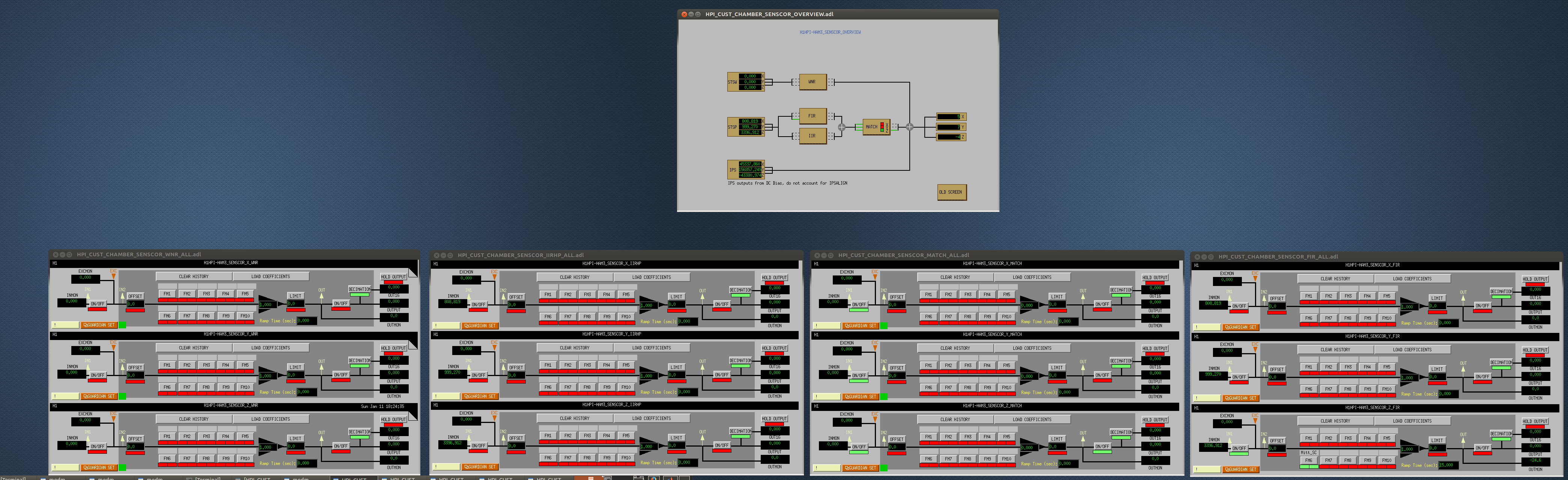
Conclusion (bis): Current configuration on HAM3
X,Y,Z,RZ: 01_28 blend
RX,RY: 100mHz blend
Sensor correction ON on X,Y,Z.