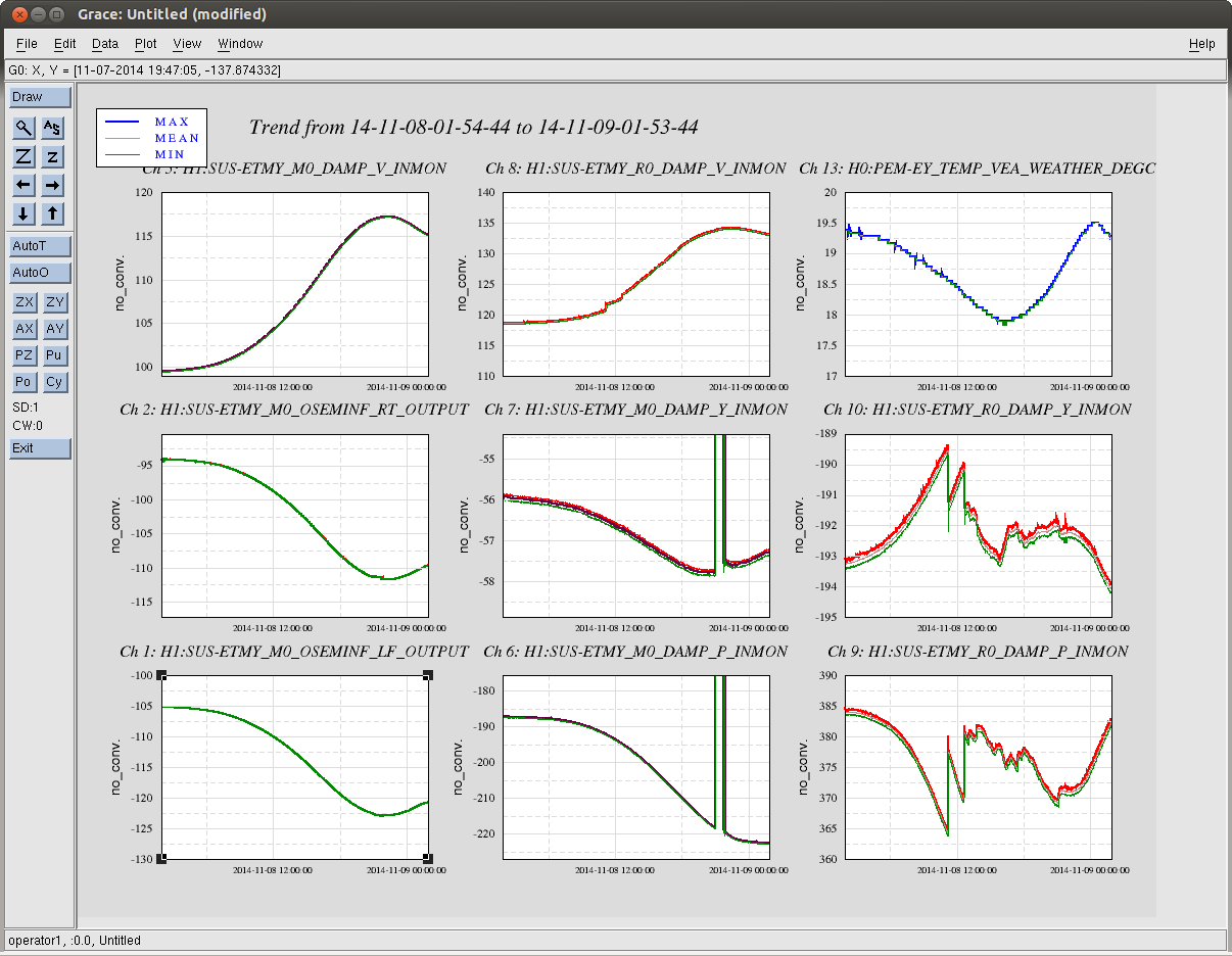
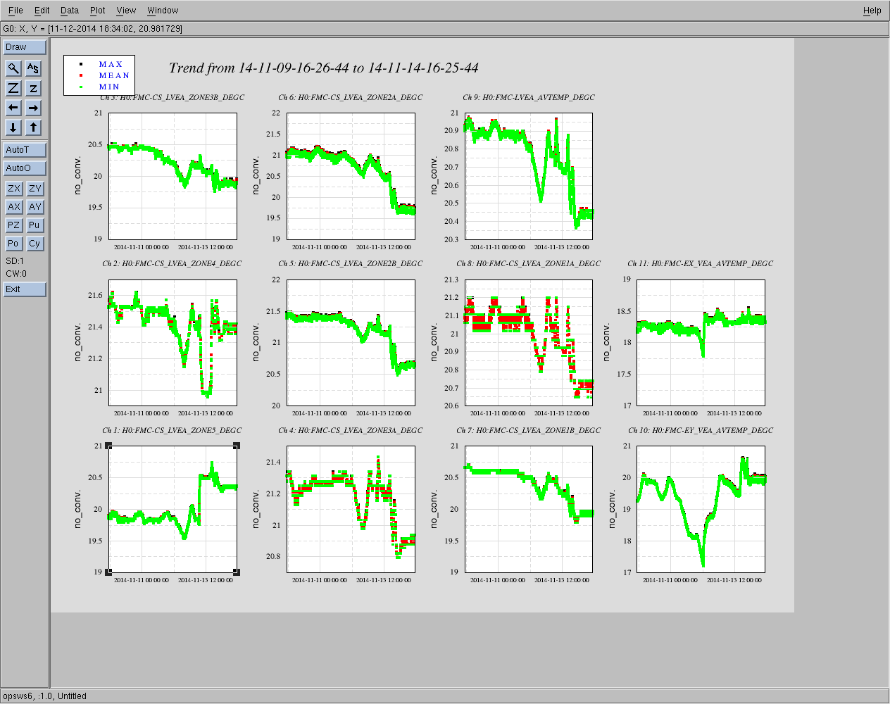
As noted over the last few days, the temperature at LHO has dropped significantly over the last few days and the HVAC temp control of Ey and the LVEA have wandered more than normal. For the record, attached is an 8 day trend showing the temperature drop at End-Y versus the ETMy main and reaction chain vertical, pitch, and yaw positions.

In order to check model calibrations and to compare with LLO's temperature drift measuremenst from Aug (alog 14008), I looked closer at a smaller band of temperature change in the above plot. I chose a quieter time when ETMy was not being manipulated by commisioning but during a 1.5 degC temperature change in the End Y VEA on 11/08.
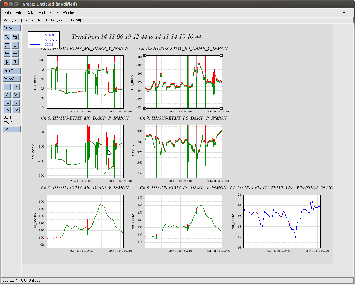
During our -1.5 degC temp change the ETMy suspension shows the following drift in Pitch and Yaw:
| ETMy M0 PIT | * ETMy R0 PIT | ETMy M0 YAW | ETMy R0 YAW |
| 35 urad | 21 mrad + 7 mrad | 2 urad | 3 urad |
With Vertical showing the following drift magnitude:
| ETMy M0 V | ETMy R0 V |
| 18 um | 16 um |
Note, the ETMy R0 (reaction chain) seems to show some stepping which we are looking into, so the drift trend has a step in between the 21 um drift and a 7 um drift.