david.barker@LIGO.ORG - posted 09:03, Friday 07 November 2014 (14904)
CDS model and DAQ restart report, Thursday 6th November 2014
no restarts reported
no restarts reported
J. Kissel, S. Dwyer, A. Staley, N Smith

Continuing Shiela's investigations from last night (see LHO aLOG 14883), we put our heads together to figure out why we're having so much trouble with the ALS DIFF control. I attach plots comparing what is currently installed against when I last was involved with the ALS DIFF design (see G1400146, and the subsequent design that was used never got published, but was designed using ${SusSVN}/trunk/QUAD/Common/FilterDesign/HierarchicalControl/DARMmodel_ALS_20140428.m). Note this is also around the time that we increased the UIM driver strength by a factor of 4, and this WAS included in my 2014-04-28 design.

Some Comments and History that I think has caused in the current badness:
- After initial installation by Kiwamu (see LHO aLOG 11665), Stefan, Sheila and Kiwamu had lowered the UIM / TST crossover a bit, from 2-ish [Hz] to 1.5-ish [Hz] (see LHO aLOG 11899). From that entry, "These tweaks served to (1) to move the elliptic filter's gain peaking bump out of the way of the 10 [Hz] features in the input noise, and (2) roll off the low-frequency end of the test mass drive faster." These adjusted filters are shown on pg 3 and 4 of the attached, shown in solid lines. The dashed lines are the original filters. One can see there's a good amount of phase action and amplitude ripple around 10 [Hz]. The cross-over action happens over a wide frequency range from 0.6 to 20 [Hz].
- At the time, we were mystified why we were never able to get to the 15 [Hz] UGF I'd designed, but we moved on before figuring it out. With some finagling, one could only get the UGFs to 5 to 10 [Hz].
- Over the course of a few weeks, Stefan, Sheila, Arnaud, and Keita began to add tweaks and patches to the plant-inversion portion of the distributed hierarchical design. This is the source of the "invL2LNEW," "patch," "LISOfit" "invL2L1," "invL2L2," "MatchedinvL2L" filters that are now used. It's unclear if this completely solved the stability problems, but it tweaked the phase in the right regions enough to certainly help. Sometimes.
- This was followed by Arnaud pioneering the length-to-pitch decoupling filters, but those installs never really went well (see, e.g. LHO aLOGs 11952, 11849, 11832).
So -- as we left ALS DIFF before the summer vent, we could only ever get the UGF up to 5 to 10 [Hz], had trouble with its stability and cross-coupling to pitch, had installed a whole bunch of high-Q plant compensation filters. Indeed, these very-precise compensation filters were measured specifically for ETMX, and then copied and pasted over to ETMY (dubious).

- Quite a bit after this, after the summer vent, we (discovered / became confident) that the actuation strength or the ESDs were lower than I modeled by a factor of 2-to-4 (see, .e.g. LHO aLOG 12220) due to charge plaguing the electrostatic drive system.
- Further, not only is it weaker by a factor of 2-4, but the strength of the ESD *varies* on the hour timescale because of continuous charge noise from ion pumps, requiring the cross-over between the UIM and TST to constantly need adjustment (needed both at LLO and LHO, but never really reported), and (I believe) occasionally moving the cross-over into instability.
- Further, further, because the charge on the quadrants evolve differently, which mean the length-to-pitch coupling is constantly evolving for this stage. We currently do not have *any* compensation for it (frequency dependent or independent).
- Distracted elsewhere, I never got back to modeling whether one could get a stable, 10 [Hz] UGF ALS DIFF loop, that did not saturate the SUS DACs. Not to mention, ground motion / SEI performance has evolved. As such, we haven't changed the cross-over of the distribution filters for the weaker, time-dependent, ESD drive.
- After finding that the highest vertical and roll modes were getting rung up with lock-acquisition, and saturating actuators, high-Q notches were added at 9 and 13 [Hz]. First to the DARM filter bank, and then moved to the UIM stage (LHO aLOG 14672). These are the "BandstopBR" that are now used in the UIM plant inversion filters. These cause substantial phase distortion near (a) the constantly evolving UIM / TST cross-over, and (b) the unity gain frequency of the loop depending on where they lived. NOTE: Sheila did NOT include these notches in her open loop gain plot (pg 1).

So things we know now that should aide new design considerations:
- The ESD actuators are weaker by a factor of 2-4, and they vary in time.
- So we need lots of gain margin both at the cross-over and the overall loop UGF.
- We should try to decrease the wide-frequency range impact of the UIM / TST distribution filters.
- We need 9 and 13 [Hz] notches in the length control path, because lock acquisition impulses cause them to ring up.
- Length-to-angle, though probably does not play a roll in the ALS DIFF loop stability at 10 [Hz], it does play a roll in the slow alignment fluctuations. In this case "slow" is both at 0.15 [Hz] as well as on the "DC drift," minute time-scale. It's unclear which stage is causing the problem.
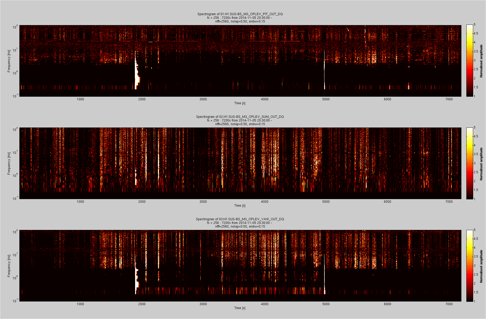
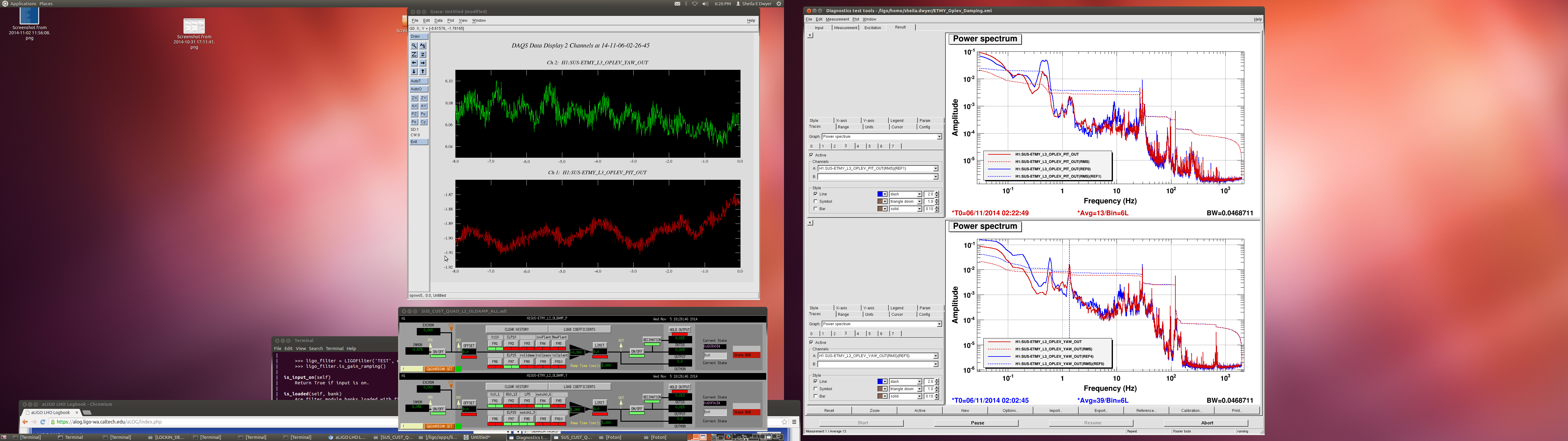
In order to see the effects of glitches in the BS oplev damping I requested that the servo be turned off for an hour yesterday.
The attached figures show the effects of turning off the servo.
1) The spectrogram shows the relative change in the pitch, yaw and sum spectra when the servo is turned off at about 1900s and turned on again at about 5000s.
1a) Note the low frequency kicks which both the pitch and yaw servos are introducing due to glitches in the laser power. Stabilising the laser power may benefit this oplev.
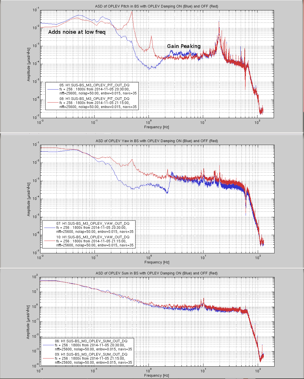
2) The ASD plots show the change in the spectrum when the damping is turned off.
2a) The Yaw damping is good over a broad range of frequencies.
2b) The pitch damping loop requires to be tuned further to reduce the servo bump between 2 - 6 Hz
2c) The pitch loop also has slightly excess noise at low frequencies.
[Hugh R. Suresh D.]
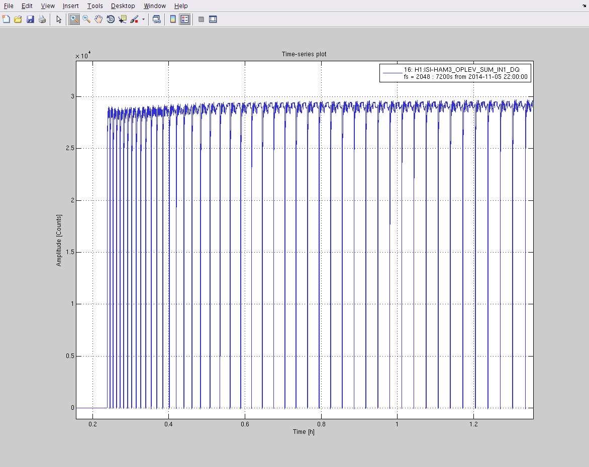
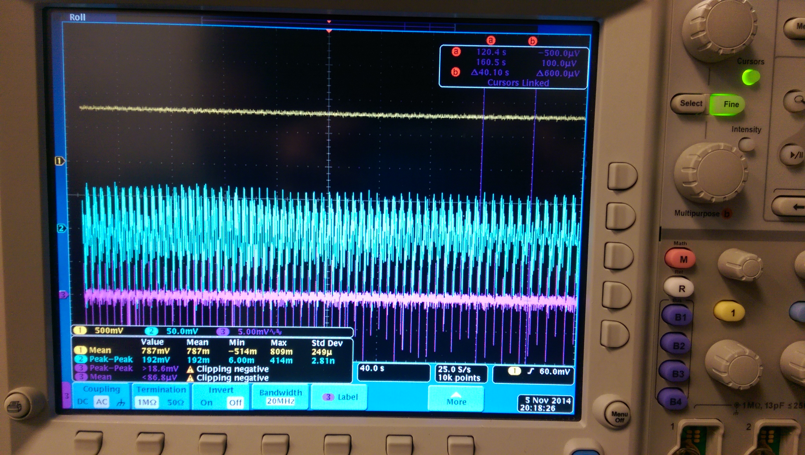
Yesterday we swapped out the HAM3 oplev laser (Sl. 122-1 was replaced by Sl. No. 199). However the Sl# 199 which had behaved well in the lab for four days chose to go into wild 100% power drops when placed in LVEA. The period between drop outs increased gradually as the laser approached thermal equilibrium (see the attached pic). However this was not a stable configuration so I brought it back to the lab and found that the problem was with the laser temperature servo. The power drop outs went away after a bit of tweaking of the servo gains and the set point (which was too high).
The Sl#199 has been replaced back in the HAM3 oplev and I am monitoring its performance.
Alastair, Greg, Eric
The X and Y tables are now almost complete. We have installed and aligned the FLIR camera, screen and cover (thanks to Greg's machining skills) on the Y-table - it currently has a beam dump in place to protect it. Main beam path on Y table also has a beam dump in place.
The power on the thermopile head at the output of the laser has been calibrated for both X and Y lasers. The rotation stages have been calibrated such that requested power should be correct (we note that sometimes you need to repeatedly hit 'minimum power' to get the rotation stage to go to the correct angle) on both tables. The on-table power meters have been calibrated for the power incident on the CP on both tables.
The X and Y tables both have flipper mounts installed and working on table, along with sensors for the mounts. The script to flip the mirrors that is connected to the MEDM screen is not yet working properly (possibly an issue with the sensors which it uses to test mask position). On the X table the flipper mounts are currently connected but out of the beam path, and the mask is being held in a fixed mount. On the Y-table the flipper mounts are both in place, however only the central mask is in its flipper mount. For this reason I've disconnected the flipper from its power supply to stop it accidentally being moved out of the beam. I've taken images with the FLIR camera on the Y-table that suggest that we could get better alignment through the mask.
Much progress on 3rd IFO storage - we've basically been through everything on site for the CO2 laser. At the moment we're still looking for the AOMs that we know are here (Thomas gave us serial numbers for these). Other than that, there are some other parts listed in ICS as being at CIT and we'll look for them there.
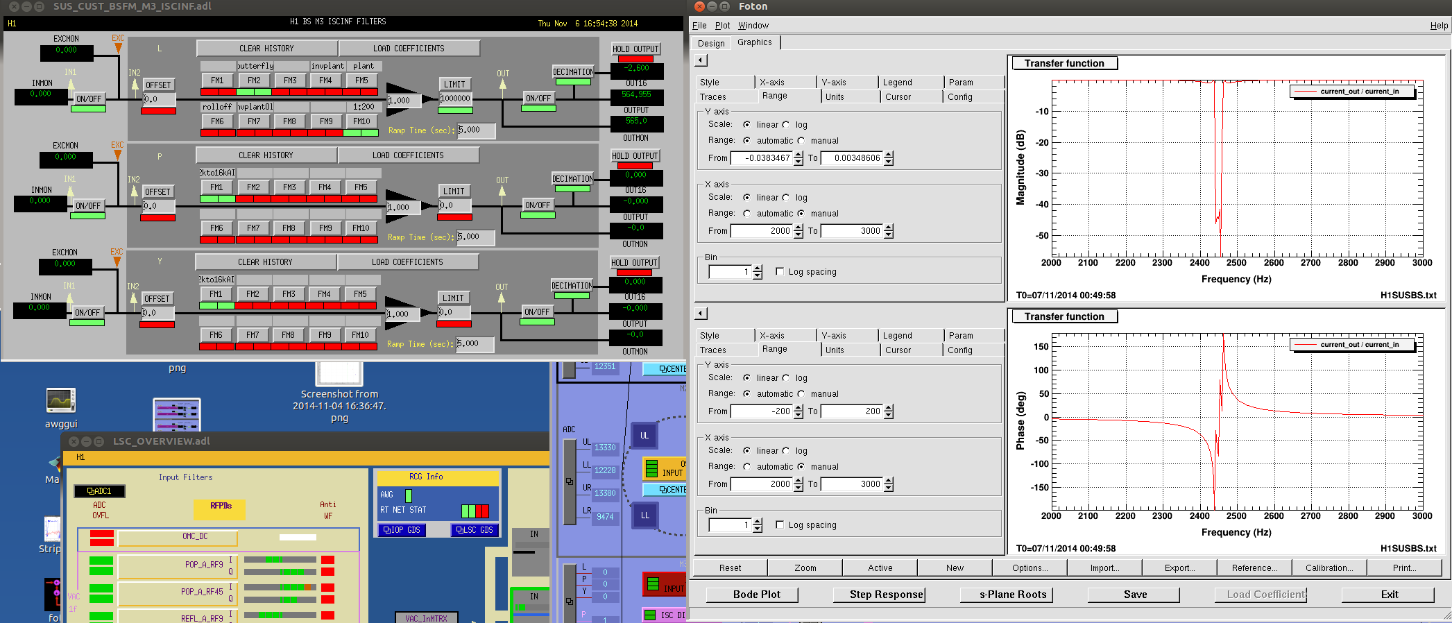
Though we are not directly touching the BS (there's no actuator for it), based on some a theory that 2449.25Hz line (https://alog.ligo-wa.caltech.edu/aLOG/index.php?callRep=14855) might be the BS butterfly, I put a band stop ellip("BandStop",5,1,40,2440,2460) in FM2 of H1:SUS-BS_M3_ISCINF_L, and turned it on.
If we continue to have this line rung up, we know that it's not BS butterfly.
K. Venkateswara
Sensor correction on X and Z at ETMX was left on last night. I turned it off this morning at 8 am as Filiberto and I were planning to work in the EX VEA. I modified the temperature sensors to take in +/-12V from the PEM power supply (thanks to Filiberto) and added a differential amplifier (with gain~50) to it.
In the afternoon, wind speeds were routinely hitting 50 mph. I've attached a pdf showing the ASD of the ground motion, BRS output and Stage 1 motion and some interesting coherences. Sensor correction was off in X and Z during this period.
Sensor correction has now been turned on and I will add plots of the result later.
J. Warner, K. Venkateswara
The X sensor correction we tried on ETMX was producing too much longitudinal motion in the X-arm at low frequencies. Sheila had to turn it off at 1:30 AM local time, this morning.
I've attached an ASD plot showing the GND_T240, GND_Super-sensor and Stage 1_T240 all along X. While SC improves Stage 1 motion above ~50 mHz, it injects a huge amount of low frequency motion. I think there are two main reasons for this:
1. While the super-sensor is likely measuring real displacement above 50-60 mHz, it is mostly measuring noise below ~30 mHz (see Brian's detailed SEI alog 602) . I'm still investigating the reason for this but it may not be an easy fix.
2. The SC filter is too aggressive (for the noise we have). Shifting it up to a higher corner frequency/faster roll-off may reduce low-frequency motion while hopefully keeping some of the benefit at 0.1-0.5 Hz.
Attempts are being made at better modelling. I apologize for rushing things without clearer understanding but hopefully, modelling and understanding will converge soon :)
08:13 Jeff B. and Andres moving 3IFO storage equipment in LVEA
08:26 Hugh restarting end Y HEPI database
08:29 Krishna retrieving tiltmeter thermometers from end X
08:49 Ed, Manny and Filiberto re-routing PEM cables at end X (WP 4935)
09:42 Alastair connecting sensors on TCS X and TCS Y tables
10:00 Cris checking for water leaks under rollup door at end Y and mid Y
10:21 Karen cleaning at end Y
10:27 Vending machine delivery truck through gate
10:32 Vending machine truck through gate
10:34 Cris back from end Y and mid Y
10:57 Kyle picking up tools and running scroll pump for ~ 30 seconds at end Y
11:16 Karen done at end Y
11:45 Gerardo taking inventory of cameras and illuminators at end Y
11:45 Kyle back from end Y
12:06 Gerardo done at end Y
12:53 Filiberto done at end X
13:07 Filiberto picking up tools at end X
13:08 Mitchell and Andres retrieving tooling from LVEA
13:13 Gerardo taking inventory of cameras and illuminators at end X
13:24 Mitchell and Andres back from LVEA
13:45 Jeff B. and Andres moving 3IFO storage equipment in LVEA
14:05 Gerardo done at end X
14:20 Dan taking picture of board at HAM6
14:20 Travis escorting visitor on tour through LVEA
14:50 Jeff B. and Andres done
15:49 Jeff K. taking tour through LVEA
16:13 Jeff K. out of LVEA
Continue cleaning up PEM cabling. This morning we powered off the PEM AA chassis and disconnected all floor bnc cabling for PEM Tilt, Seis, Mic, Magnetometer, and infrasound mic. The cables were pulled back and routed into cable tray over the beam tube. All excess cabling was cut off (up to 20 ft on some cables) and re-terminated.

Few cables left to terminate, ran out of time before noon deadline. Plan to run MIC and Op Lever power cables tomorrow.
This entry summarized the status of REFLAIR_B signals. REFLAIR_B is the broadband photodetector, D1002969, mounted in reflection of the interferometer which is responsible for measuring the 3f signals at 27 MHz and 136 MHz in DRMI. The 3f signals are relatively weak, especially at low modulation depth. This has lead to a low signal-to-noise ratio at sub milliampere photocurrent and distortion problems above a milliampere. The problem of saturation by out-of-band intermodulation products was recognized early on a LLO and fixed with a diplexer amplifier, D1300989.
The situation at LHO and LLO are essentially the same.
Koji has recently measured the second order intermodulation products of the RF chain in the broadband photodetector and found the second order intercept point to be rather low, around 30 dBm. This is maybe not too surprising considering these RF amplifiers are single transistors or Darlington configurations operated around a fixed DC working point. No specification of the IP2 is given in the datasheet.
This leads to the conclusion that 3f signals at LHO are predominantly due to intermodulation distortion in the RF amplifier chain and not due to the optical signals. This obviously works just fine for the DRMI, but probably doesn't give the required immunity to the carrier mode for full interferometer locking.
Possible solutions:
Increasing the modulation depth and reducing the photocurrent at the same time will not improve the situation, since the distortion depends on the absolute signal strengths of the individual RF lines. However, removing the first amplifier stage should give us enough room to further increase the modulation depth and improve the signal-to-noise ratio. Using a high modulation depth during locking may require an adjustable EOM driver, such as the, D0900760.
Summary
- Follow up measurement for the alog above was done.
- It was confirmed that the first preamp (MAR-6SM) is creating the domnant intermodulation and we will be able to improve it
by removing this first preamp as suggested (by costing some noise increase).
- It may become overkill if we are going to apply notch filters as being tested at LLO. Therefore it is also planned to test other amplifiers
that are similarly low noise to MAR-6SM, and are located between MAR-6SM and GALI-6 in terms of the intermodulation performance.
2nd-order & 3rd-order intercept points (IP2/IP3)
To quantitatively confirm Daniel's expectation above, I took measurements of the amplifier IP2/IP3.
IP2 and IP3 for an amplifier are defined by from the amount of harmonic distortions as
P2 [dBm] = P1 [dBm] x 2 - IP2 [dBm]

	P3 [dBm] = P1 [dBm] x 3 - IP3 [dBm]
Here, P1 is the power of the linear output, and P2/P3 are the power of the 2nd/3rd harmonics.
When P1 reaches IPn, Pn becomes equal to P1. i.e. the output starts to be dominated by the n-th order.
Of course, we usually can't drive the amplifier at that level, this is purely a mathematical way to quantify nonlinearlity of the amplifier.
Basically the power of the bilinear intermodulation can also be estimated with IP2 in the same way as above.
Just replace P1 with the total power of two signals into the formula for P2. There may be some factors like 3dB, but just forget about it for now.
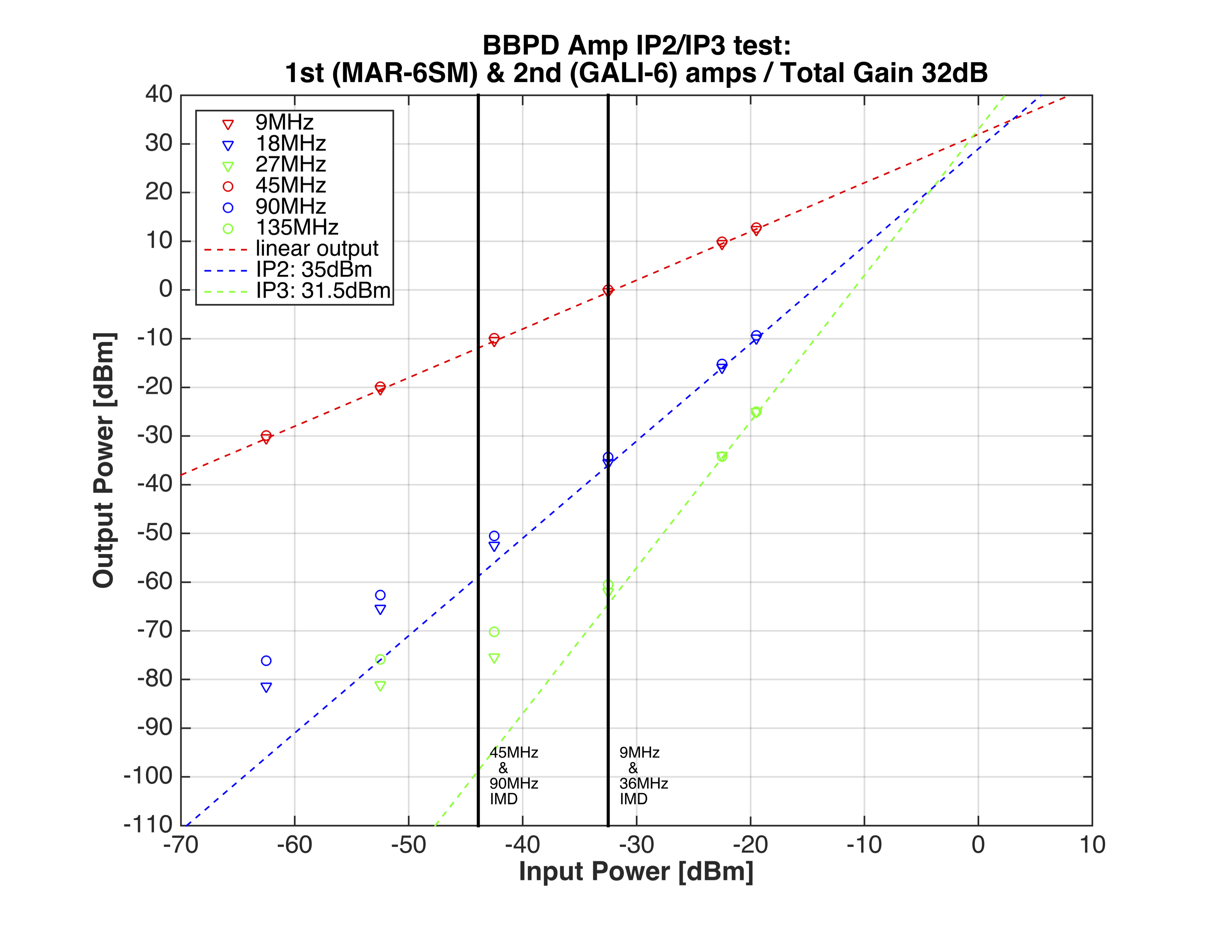
TEST1: Nominal configuration (MAR-6SM + GALI-6)
In order to measure IP2/IP3 of the nominal amplifier configuration of the BBPD, the input power was swept from -60dBm to -20dBm.
The input frequencies of 9MHz and 45MHz was used in order to check the frequency dependence. In fact, there was no significant
frequency dependence as we'll see in the result. Therefore only the input frequency of 45MHz was used in the other measurements.
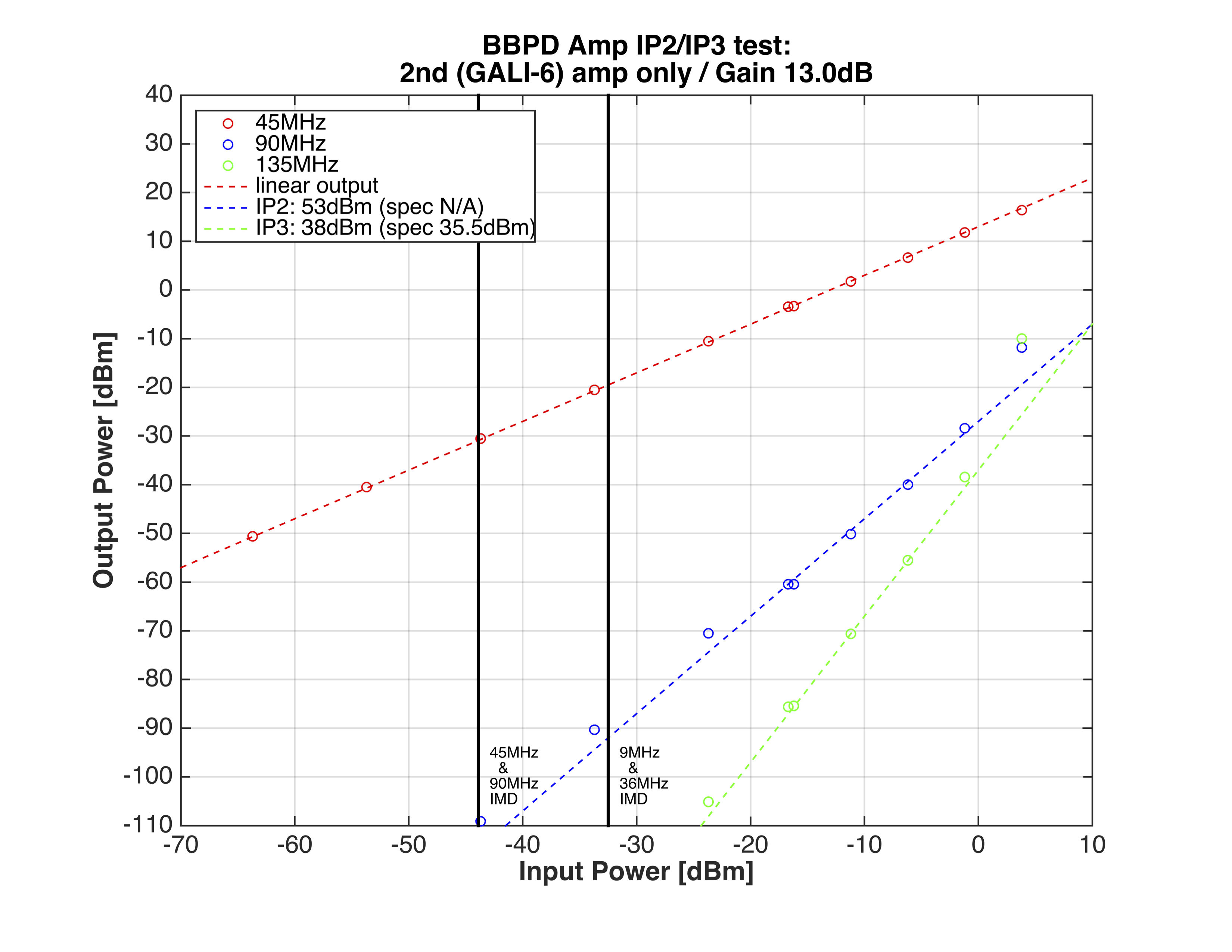
Attachment 1 shows the relationship between the amplifier input power and the output power at the fundamental, 2nd harmonic,
and 3rd harmonic frequencies. The lines were manually applied to illustrate IP2/IP3. From the line for the linear power (red), the gain of
the amp chain was determined to be 32dB. In this configuration, IP2 and IP3 were 35dBm and 31.5dBm, respectively.
Practically, we want to know how much intermodulation (IMD) we produce when the amplifier is connected to the IFO.
I gazed Evan's measurement (14807) again and determied the combined power for 9MHz+36MHz, and 45MHz+91MHz to be
-0.5dBm (-32.5dBm at the input) and -11.9dBm (-43.9dBm at the input), respectively. These are indicated as the vertical black lines in the figure.
We expect to have -0.5*2-35 = -35.5dBm of IMD for 27MHz, and -11.9x2-35 = -58.8dBm of IMD for 135MHz. That is not too far from what we see
from Evan's meausrment. (Sanity check)
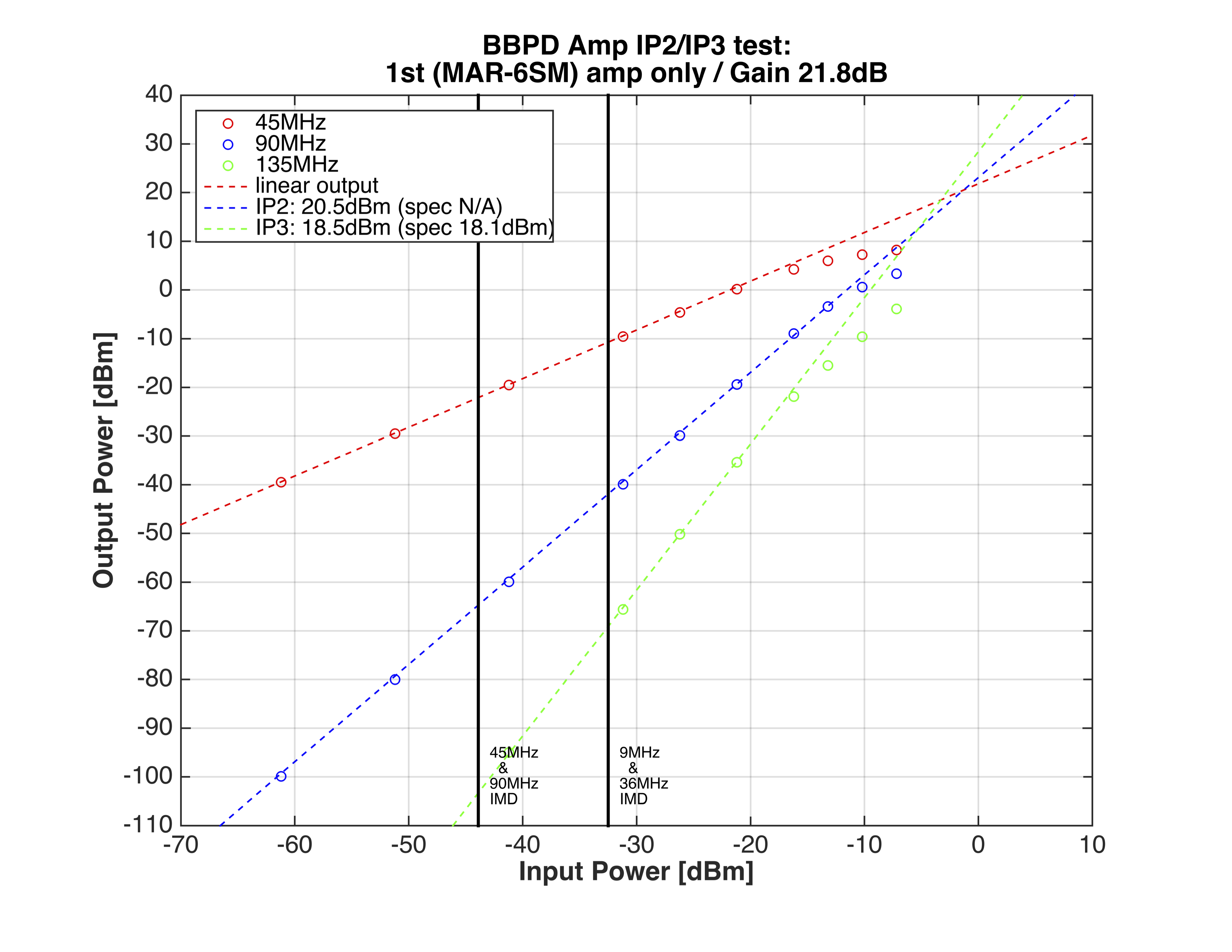
TEST2: The 1st preamp only (MAR-6SM)
Attachment 2 shows the same measurement only with the first preamp (MAR-6SM)
Roughtly to say, IP2 of MAR-6SM is reduced by a factor of 14.5dB, which is close to the gain of the second amp (13dB).
This means that the IMD performance of the chain is limited by this amp. Minicircuits show IP3 only in the spec sheet.
The measured value (18.5dBm) is close to the spec (18.1dBm). (I'm not insane)
TEST3: The 2nd preamp only (GALI-6)
Attachment 3 shows the same measurement only with the second preamp (GALI-6)
This amplifier has much better IP2/IP3 than the 1st one. Again the measured IP3 (38dBm) is close to the spec (35.5dBm)
This measuerement indicates that we'll have the IMD of -70dB and <-80dB relative to the source of the IMD when the first amp is removed.
Drawback & some other possibilities
As Daniel pointed out, the second preamp has worse Noise Figure than the first one. So we expect to have worse noise level in terms of the shotnoise intercept photocurrent.
Also Matt is testing on-board notch filters at LLO. If we consider to apply some notching, this GALI-6 could become overkill.
I ordered some other amplifiers like GALI-39, GALI-52 (Daniel's pick), and MAR_8A. They are similarly low noise to MAR-6SM, compatible packages
to the PCB, and located between MAR-6SM and GALI-6. Once they arrive, I'll carry out the same tests.
Betsy, Travis
This alog represents the last ~month of intermittent assembly work on the 3IFO QUAD unit "Q7".
After switching out 3 problematic wire segments and the entire set of top stage blade cartridges, we have finally launched a first round of testing on Q7 this morning.
Details:
After assembling and fully suspending Q7, we had a difficult time bringing the 6 DOFs of each chain into coarse alignment. We discovered that the top most blades used in the QUAD were the softest of any QUAD unit thus far, as per the stiffness catalog T1000068. In fact, this set had a much wider variation in stiffness than any other unit as well which was adding to our challenge. We decided that we should delegate this set of blades to the spare bin and swap them with another set. After swapping in a set from the middle of the stiffness range (Tops Set 7), we saw the QUAD chain alignment was much improved in side shift. We then continued to struggle with differential height. We decided that we might have had a wrong wire segment length lower in the chains so we first switched in new main chain PUM loop which had no effect, and then switched in a new set of reaction bottom and final wires which did help our differential height issue. (We confirmed the removed sets were ~1-2mm longer than the new set although we really don't know which is "correct".) With all of this new hardware, we were able to align the chains to within the coarse specs. We laced up the reaction chain lower stages and readjusted alignments and suspension mechanical groundings. Yesterday we assembled the top mass tablecloth and cabled/attached/aligned top 12 BOSEM sensors. Today we are running TFs.
Over the past 2 days, there has been a series of earthquakes (26 so far, ranging from 2.5 to 4.7 magnitude) near Lakeview, OR, approximately 400 miles south of LHO. Something for commissioners to keep in mind as they struggle to lock the IFO. See attachment.

re WP 4913
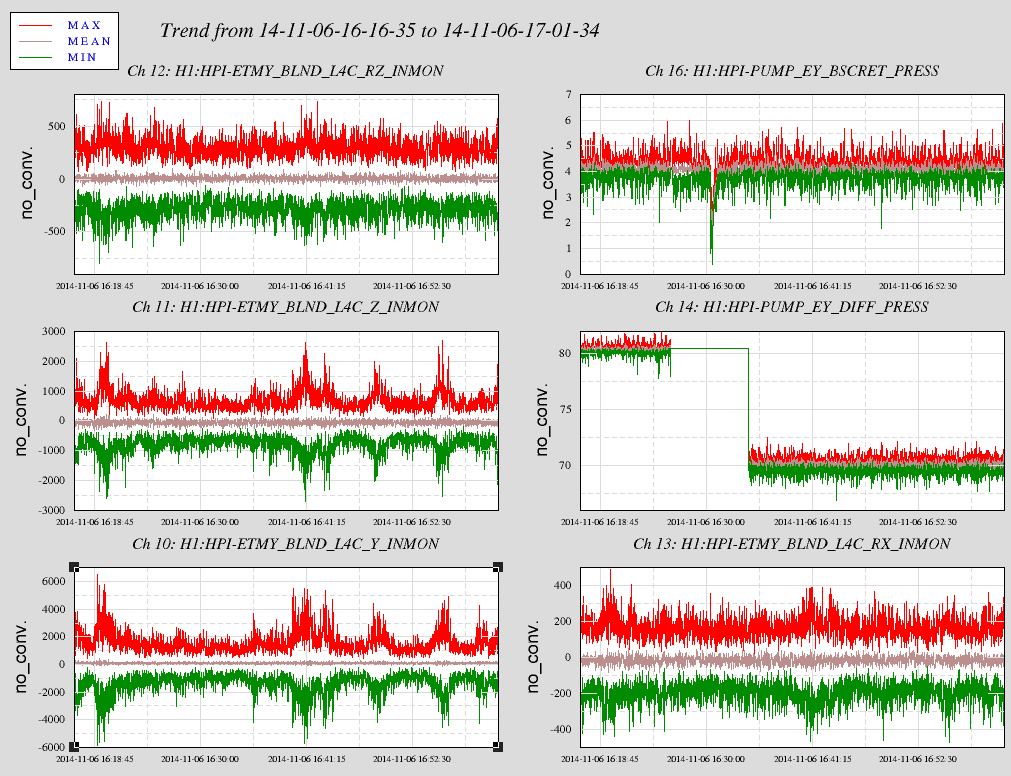
I switched the HEPI pump Servo to run on the true differential pressure as LLO has been doing forever. I did glitch the system through my sillyness. I was all ready to do it without any serious glitch and next time it will be better. Still, the HEPI position loops on the platform did not trip--pretty good support for the hydraulic system. The differential pressure now does look slightly noisier based on the time series. But of course this is now a sum of two noisy signals, maybe time for some smoothing and serious grounding study.
Attached is 45 minutes of second trends for the Pump station channels and some cartesian basis HEPI L4C signals. I don't see any ill affects of this transition so far.
So the alarm manager is okay as I changed the database alarms. The medm though is also common so if you open the EndY HEPI Pump Servo medm, it will show pressure not okay. When it is deemed okay to continue down this path, I'll update the medm when I install the same database changes at EndX.
no restarts reported
Nic, Alexa, Sheila, Evan, Dan
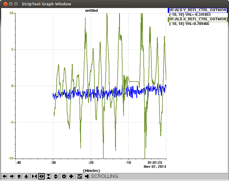
We wanted to measure the crossover between L1 and L3 of ETMY. We took a transfer function from LOCK_L1/L3 to ALS-Y_REFL_SERVO_CTRL_OUT with green locked to the yarm. We found an old template made by Sheila and Stefan for the L1 stage. We repeated the measurement for a few data points (green trace), and it seemed the same as the old measurement (blue) so we aborted the measurement and went with the assumption that it was still a valid measurement. We then measured for the L3 stage (red trace). Clearly the crossover between L1 and L3 is about 2 Hz as expected. Nic plans on dividing these two transfer functions tomorrow morning...
Fo reference the xml file is located here: /ligo/home/sheila.dwyer/ALS/HIFOXY/Y_UIM_2.xml
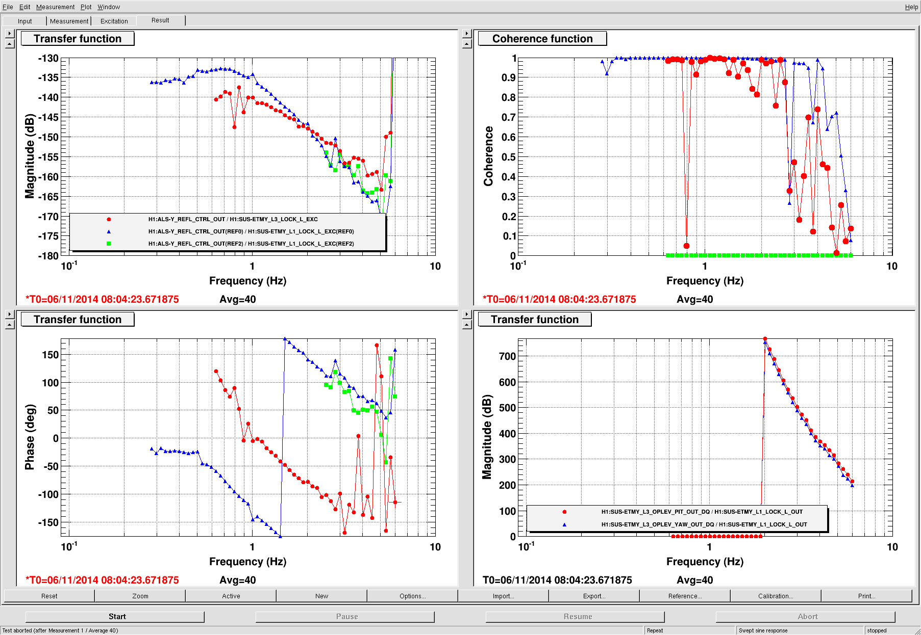
Here is the ratio of the ETMY UIM and ESD actuator gains (red and blue traces in original post).
It looks like our crossover is about 2Hz and the phase margin is about 45 degrees.
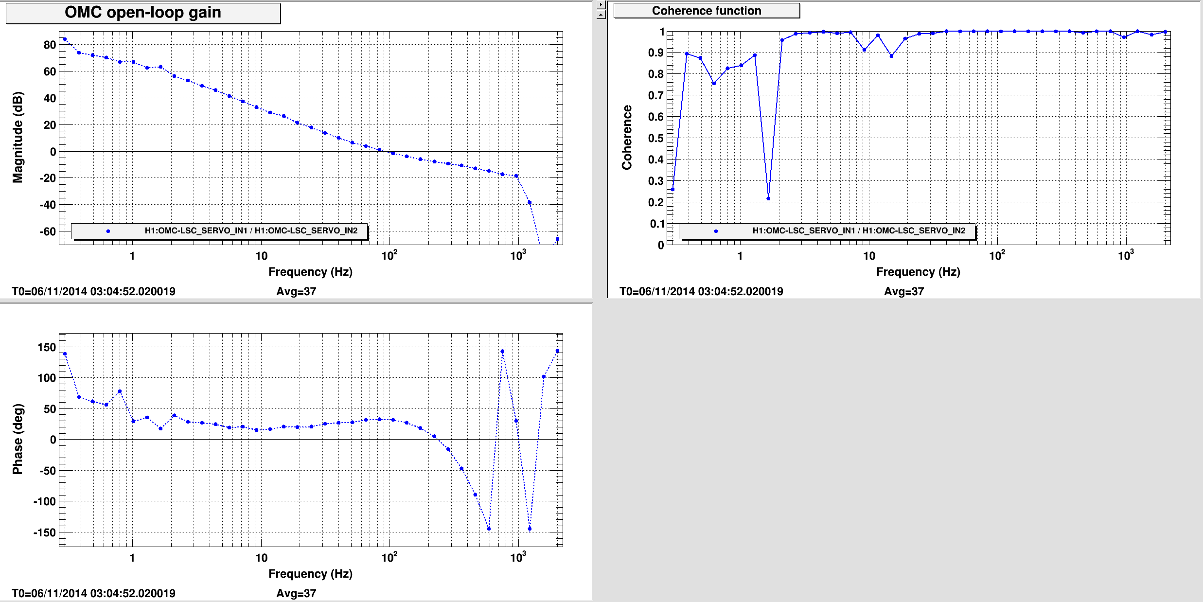
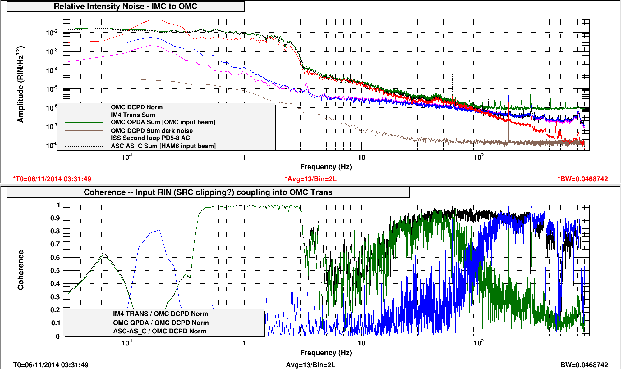
After spending far too long scratching my head about calibrating the OMC DCPD signals, I've measured the RIN of the OMC transmitted beam, and it's not pretty.
To make the measurement I locked the OMC on the side of a carrier TEM00 fringe, as described here. I measured the open-loop transfer function; this is the first plot attached (UGF is 100Hz, which is about the same as when we're dither-locked on the peak of the fringe with much higher gain in the LSC servo). To calibrate OMC-DCPD_NORM into true RIN I divided by 1/(1+G) in DTT so that the loop suppression is accounted for. To calculate the RIN seen by other PDs, I divide by the PD sum at DC.
The results, in the second plot, show that the beam incident on HAM6 has some issues. At high-ish frequencies, 100Hz and up, the OMC Trans intensity noise is due to noise out of the mode cleaner. It's coherent with IM4 Trans and the ISS second loop PDs. Probably this noise can be mitigated using the ISS second loop and also reducing the IMC angular fluctuations that were described by Gabriele.
At low frequencies, between about 0.2 and 3Hz, there is huge intensity noise on the input beam to HAM6 beam that is not seen just after the IMC (neither IMC_TRANS or the ISS second loop PDs). The noise is seen in HAM6 by the OMC QPDs (in green - limited by electronics noise above 50Hz?) and by ASC-AS_C (dashed black). At high frequencies the intensity noise in HAM6 is coherent with the noise out of the IMC, but the loud stuff around 1Hz is likely due to the clipping that Keita measured yesterday.
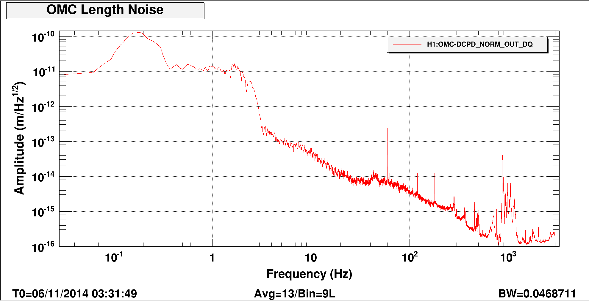
The third plot shows an attempt at characterizing the length noise of the OMC; the loop-corrected RIN was converted into meters using the derivative of the usual Fabry-Perot transmission formula at half-resonance (the conversion factor is 3.7e8 RIN/meter). This is a first step towards building an OMC noise budget, following the work by Zach at LLO. At high frequency (around a kHz), the noise begins to drop below the limit of 3x10^-16 meters/rt[Hz] prescribed by Valera's estimate in G1100903, but there's a forest of lines around 1kHz that's not unlike what was observed at L1. At lower frequencies, the noise seen at the DCPDs is dominated by the input intensity fluctuations, and it's not possible to measure the length noise that's intrinsic to the cavity. The photocurrent during these measurements was about 3mA for each DCPD (shot noise RIN of 10^-8/rt[Hz]).
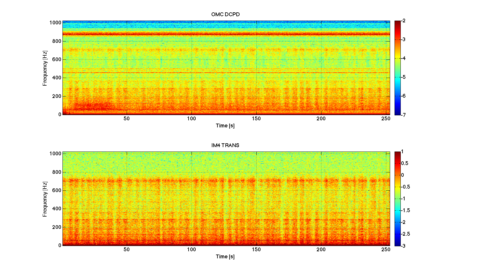
Most of the noise between 50 and 800 Hz is largely non stationary, as visible in the spectrogram (figure 1). It is also clear that the non-stationarity is very similar to the one we see directly in transmission of the IMC
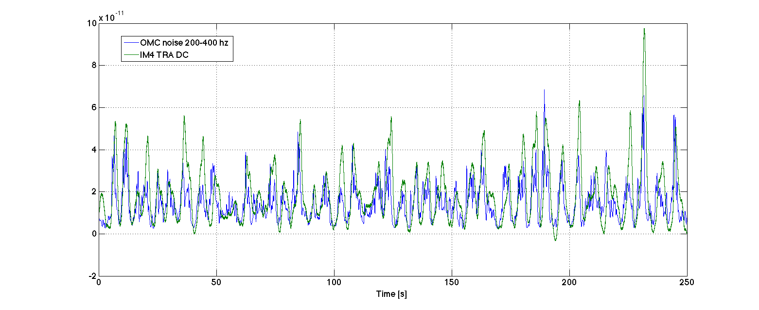
This non stationarity is, as expected, closely related to angular motions of the IMC. In particular, the noise fluctuates in the same way as the IMC transmitted power (figure 2). My guess is that the DC alignment of the IMC is again not very good.
Alexa, Evan
The ETMY oplev damping was off. We have turned both picth and yaw damping back on.
Additionally, I have tweaked the filters and the gain slightly in order to reduce gain peaking:
According to conlog, the loop gains appear to have been randomly adjusted several times over the last week.
We hope that this might improve the robustness of the ALS locking. If not, we might try a similar recommissioning of the ETMX oplev damping (since this are also off).
Nic, Evan
Last night, we were playing around a bit with the loop shape of the ETMY pitch oplev damping. We returned to the original shape, but found we could not reengage the loop without causing the optic to oscillate. It is currently locked with a factor of 10 less gain (0.3 → 0.03), which is stable but is probably not suppressing the optic motion at all.
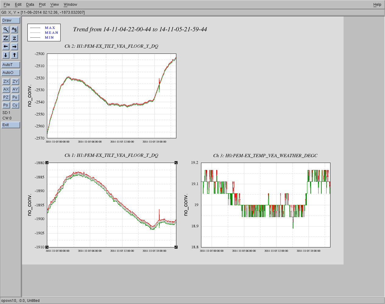
K. Venkateswara
I had installed temperature sensors on BRS and GND_T240 yesterday as described in 14825. The first plot shows the trend over a day along with the PEM_VEA temperature sensor. The count to Kelvin conversion was expected to be 1.56e-3 K/count. This seems roughly consistent with the temperature of the T240. The BRS temperature sensor shows a lower magintude and a phase offset due to it's extra thermal shielding and larger mass.
The attached pdf shows the ASD of the temperature sensors and the coherence between them and their respective instruments. The temperature sensors are mostly limited by ADC noise. An op-amp based pre-amp of 50-100 gain would be useful. BRS_RY_Out shows a little bit of coherence near few mHz while T240 X, Y and Z show no coherence with the temperature sensor.
You should add the ADC noise to this plot
I've added a comment about it in 14909. I'm not sure how to display the ADC noise in DTT. In any case, it shouldn't be limited by ADC noise any more.
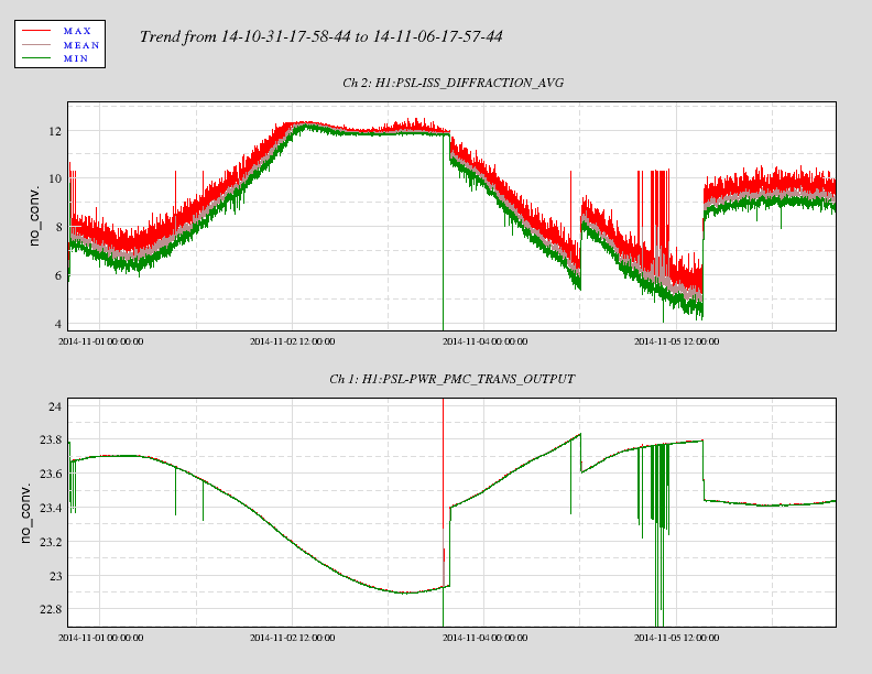
As the wandering laser intensity continues I intend to learn more about these systems. I can only report the findings and make the adjustments. ISS diffracted power is down to ~5% this morning. REFSIGNAL was at -2.04V as it was set by me yesterday. Today I have adjusted REFSIGNAL to -2.02V to bring the diff power to ~8.6%. Attached is a past 5 day trend. the spikes, i am told, are likely caused by activations on MC2? (for example)
Here is the former plot put together with the PMC trans pwr plot as requested by P King.
Evan, Sheila, Nic, Lisa

To answer Peter's questions , we have relocked the DRMI (without arms) on 1f and 3f
(10W input power, 27 mW on the BBPD photo-detector).

The DRMI was very stable in both cases, here are the good times:

 Nov 5, 6:00 - 6:15 UTC  DRMI locked on 1f, WFS on

 Nov 5, 6:30 - 6:45 UTC  DRMI locked on 3f, WFS on

Evan is about to post plots with error signal spectra.

It is probably a good idea to make some plots with ground motion/ISI/optical lever signals to "capture" these good times.
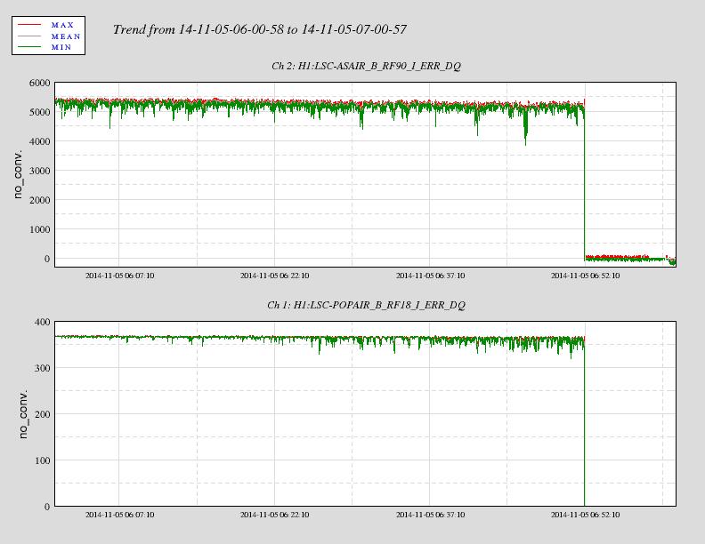
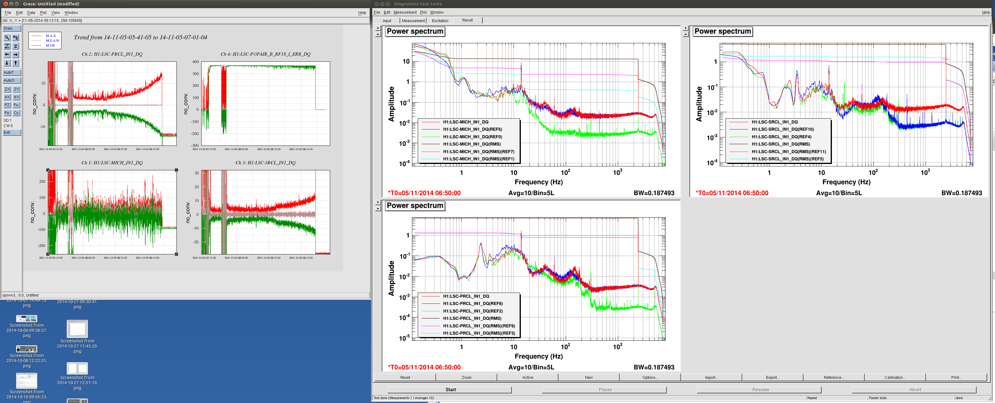
These are the corresponding RFPD spectra. The analogous LLO measurement is LLO#15430. LLO's measurement of RF135 seems pretty surprising, since the 3f demodulated spectra appear to be almost entirely noise-dominated above 20 Hz.
What's this 2449.25Hz line that grows over time?
In the attached left, the error signal for PRCL and SRCL grew larger and larger toward the end of the lock.
In the attached right, red, blue and green correspond to the end, middle and the beginning of the lock. The difference in noise floor might be that they were switching from 1f and 3f or vice versa.
Regardless, a line at 2449.25Hz grew larger over time and it was dominating the error signal RMS.
Is this something intentional? Oscillation somewhere? Rogue line?
I am not sure what the 2449.25 Hz line is; there is not a line there that I know of...
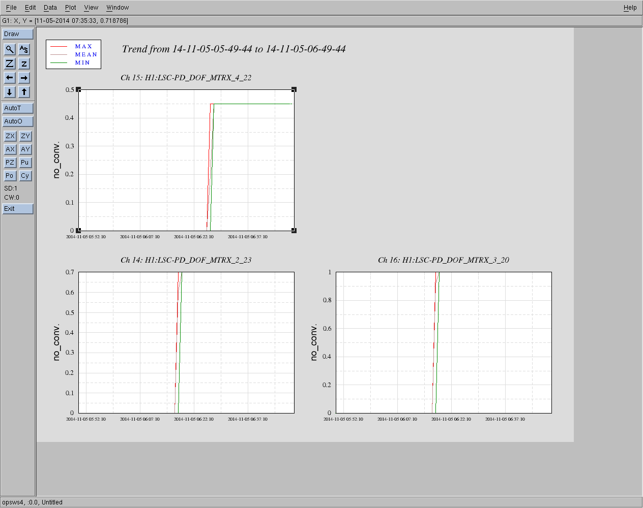
In terms of the difference in the noise floor, I can confirm that this comes from the 1f to 3f transition. Keita's green trace was taken from 5:50 PM UTC, blue trace from just after 6:20 PM UTC, and red trace was taken at 6:50 PM UTC. I have attached a dataviewer snap shot showing the LSC PD input matrix of the MICH (2_23), PRCL (3_20), SRCL (4_22) 3f signals around that time. The MICH and PRCL signal transistion at around 6:17 PM UTC, which explains why the blue and red traces in those plots go up. Meanwhile, SRCL transitions a bit later at 6:26 PM UTC, which explains why only the red trace goes up in the noise floor.
According to Dennis the lowest elastic mode of the beamsplitter is expected to be at 2458 Hz (right circular cylindrical without wedge angle, bevels, wire standoff-prisms).
