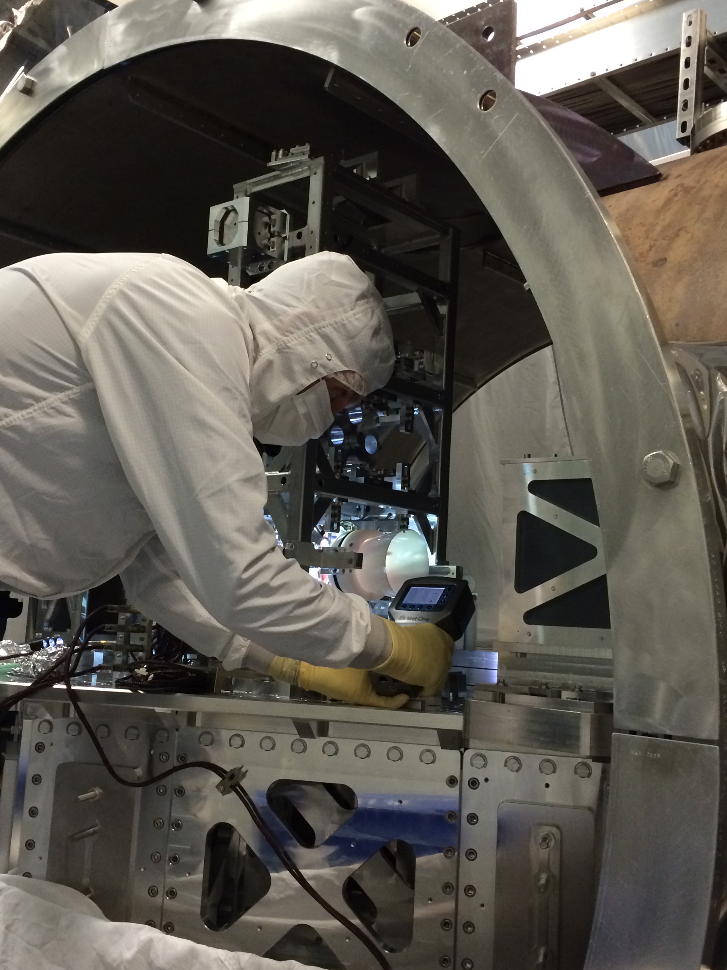
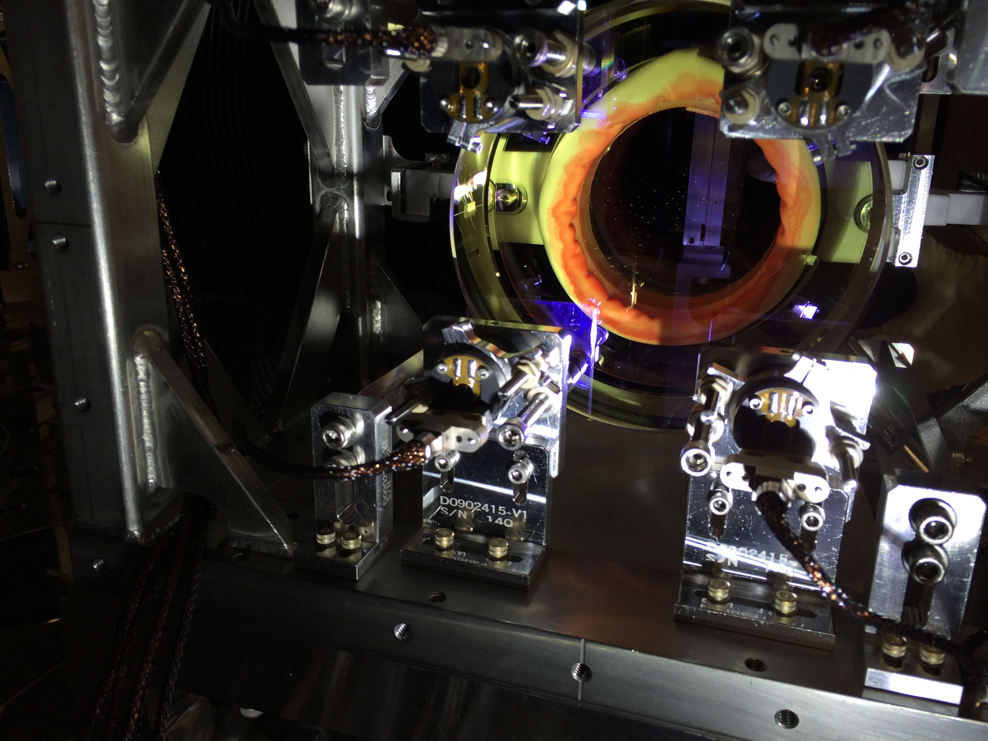
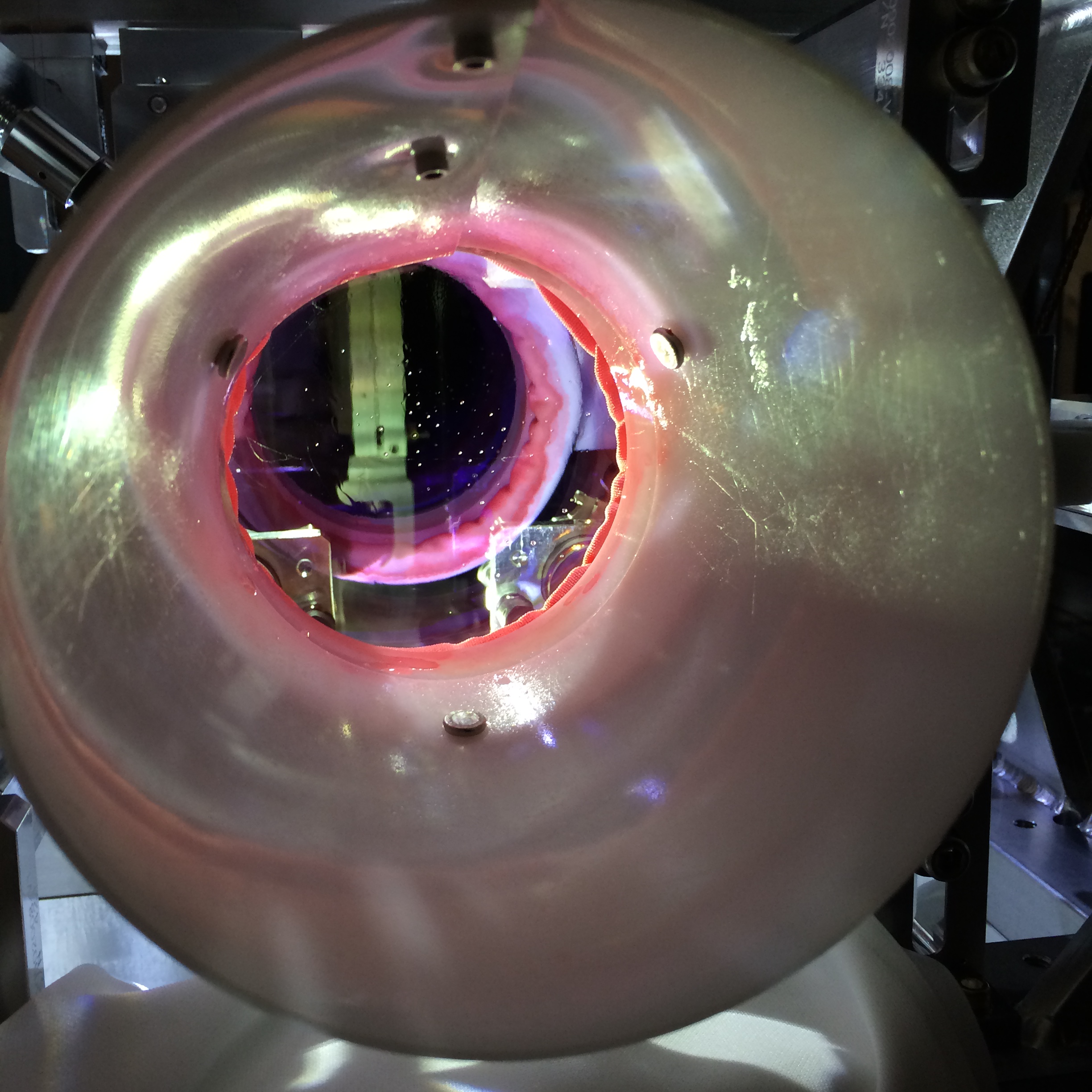
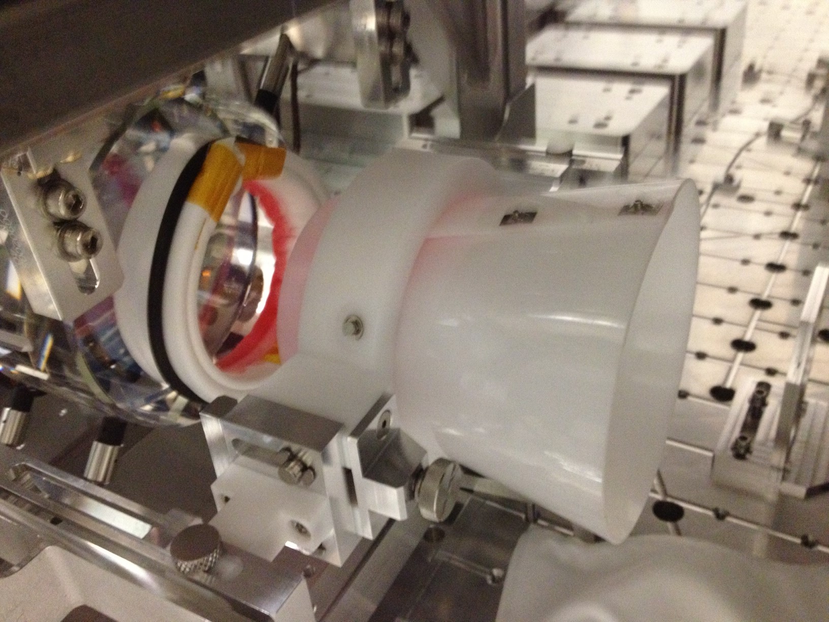
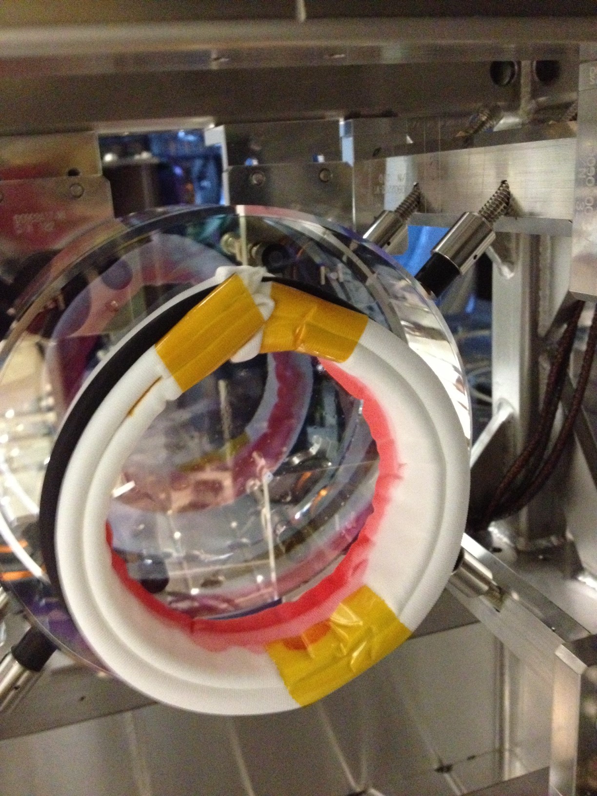
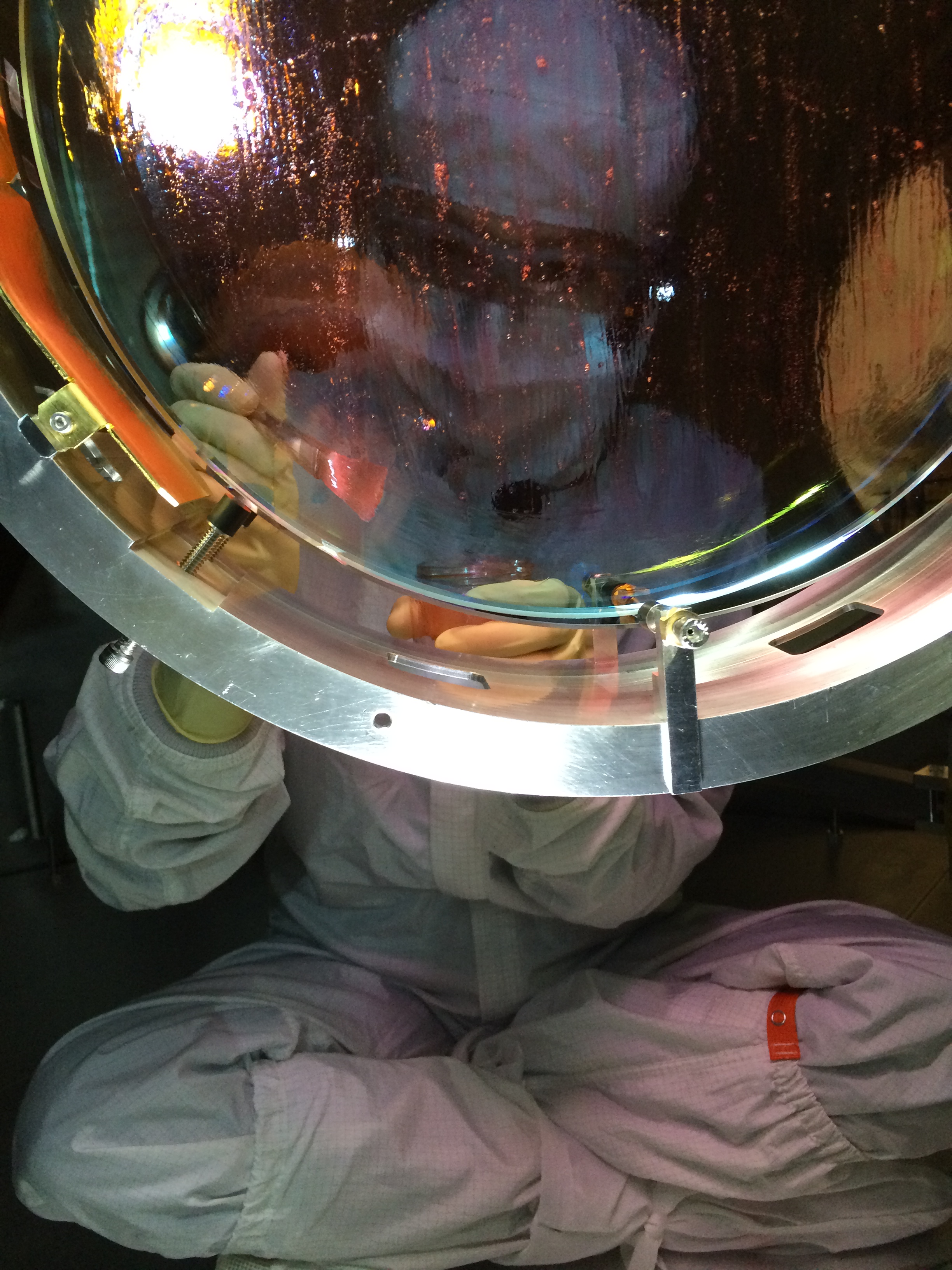
This morning after Jim locked the BSC1 ISI, I applied First Contact to the ITMy CP-AR surface via the spray cone technique. We then made final preps to the SUS locking down nuts, closing the ring heater, etc.
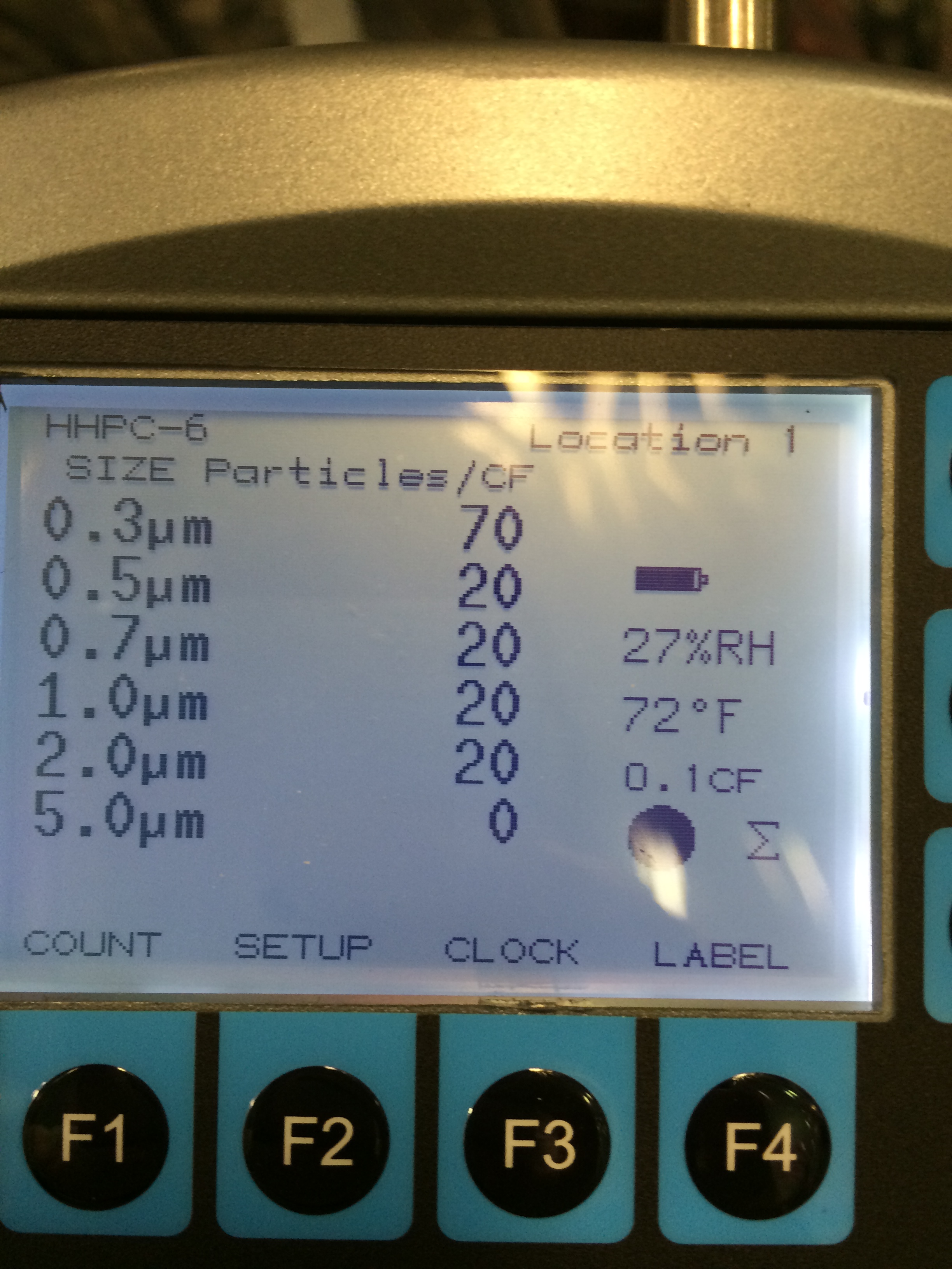
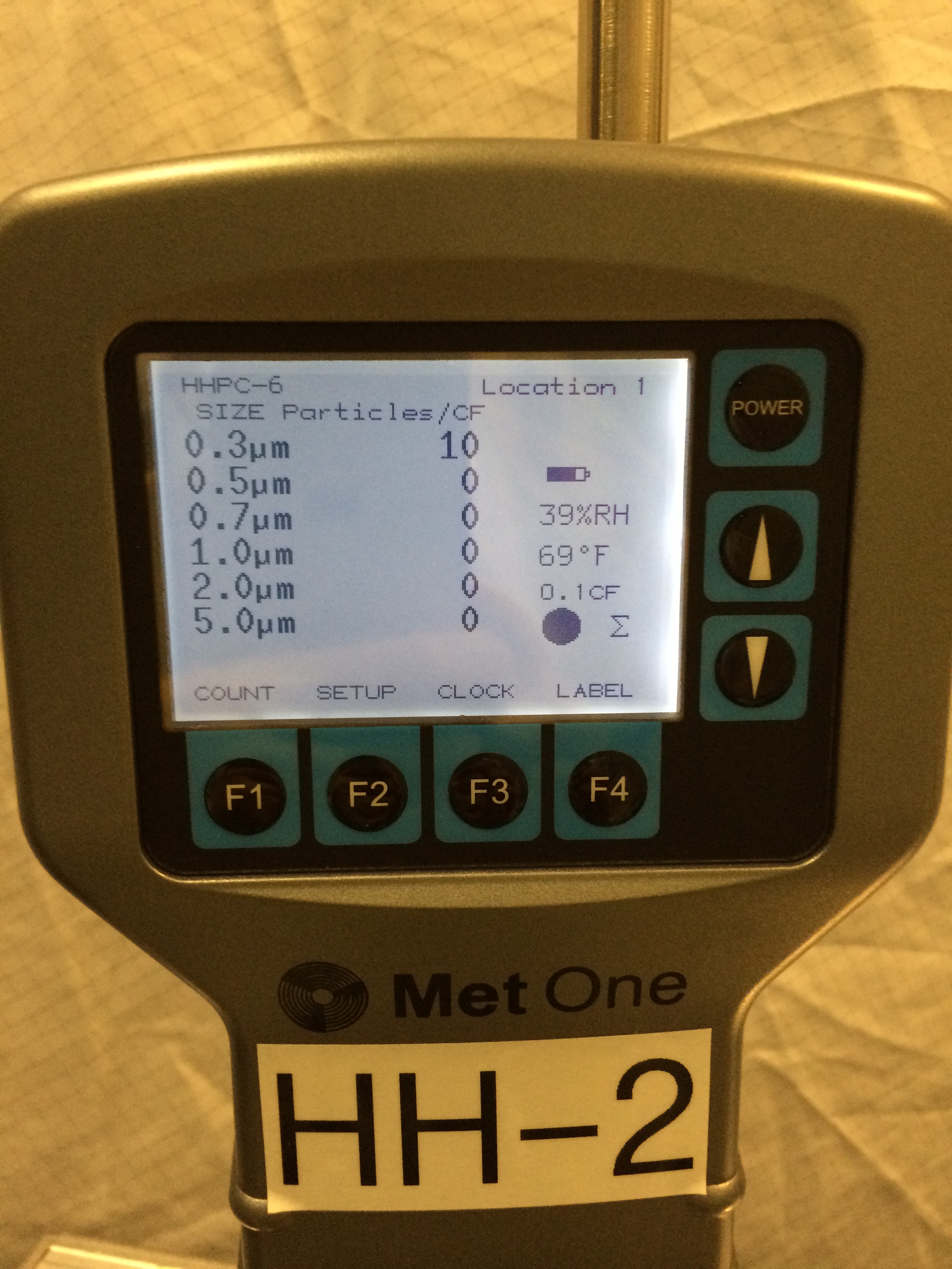
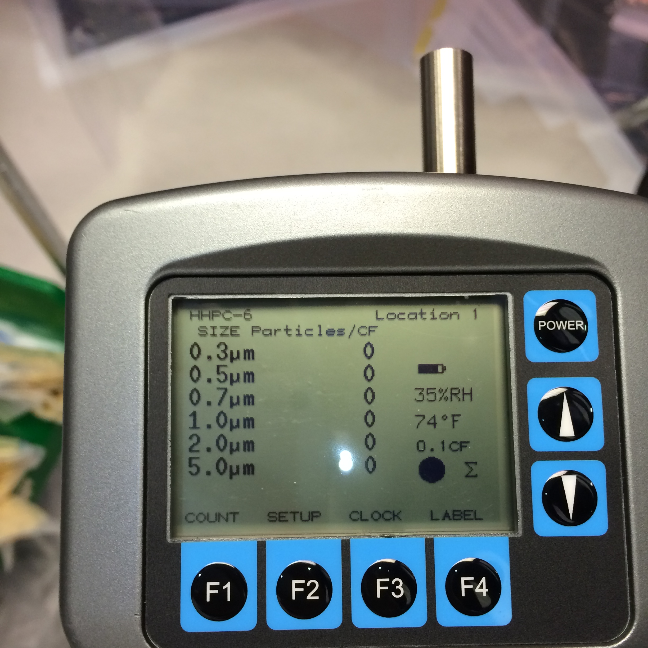
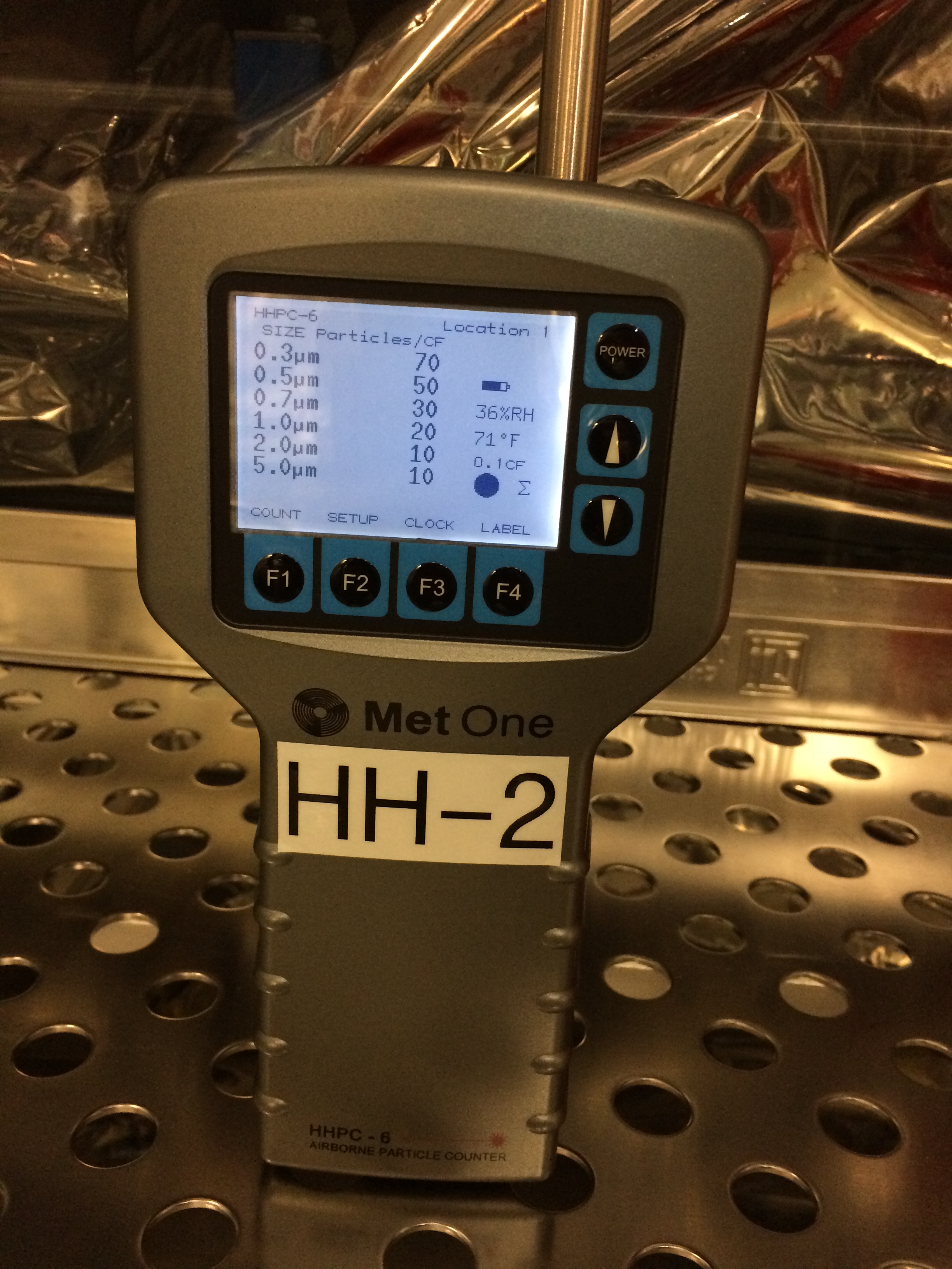
Particle counts in chamber before we started, but after Mitch had walked through for access to the X-spool ~an hour earlier:
0.3um 30
0.5um 10
1.0um 10
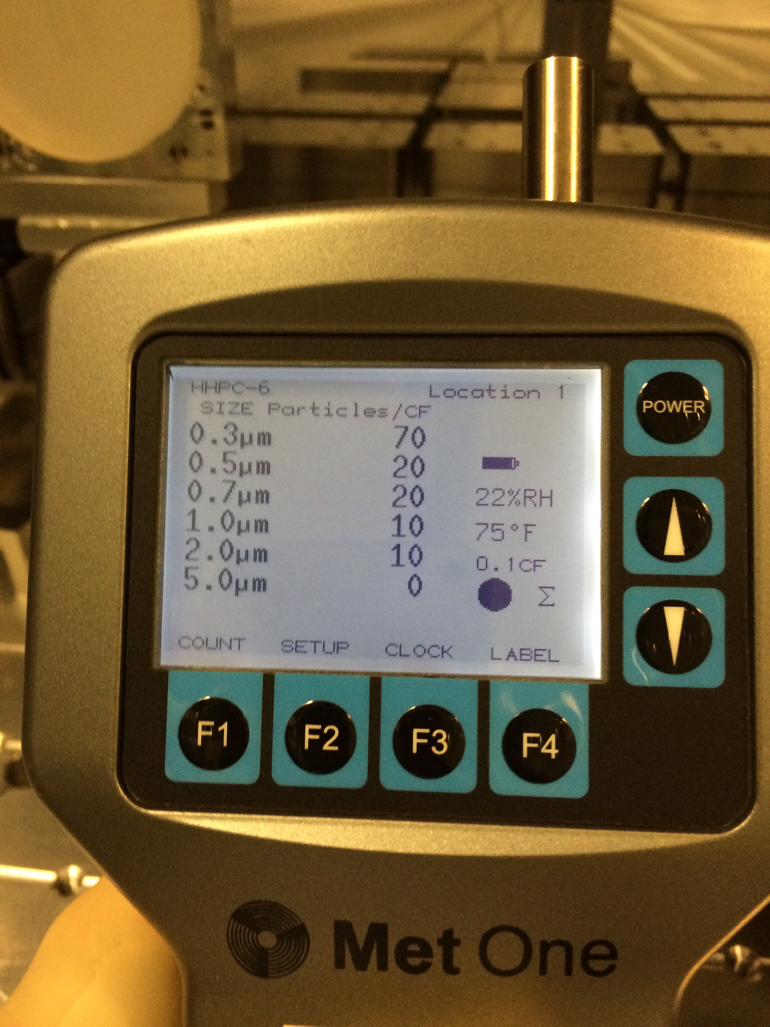
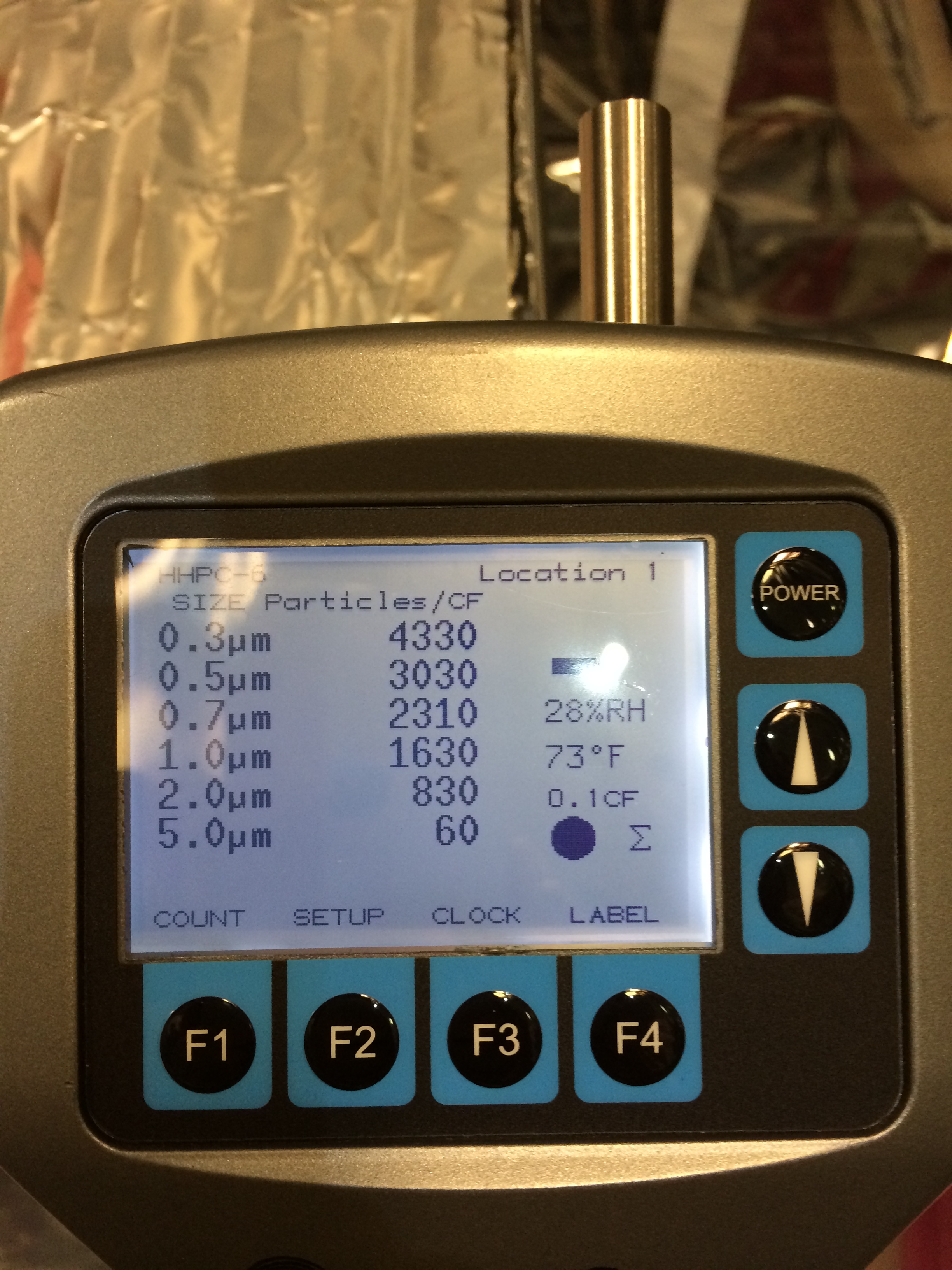
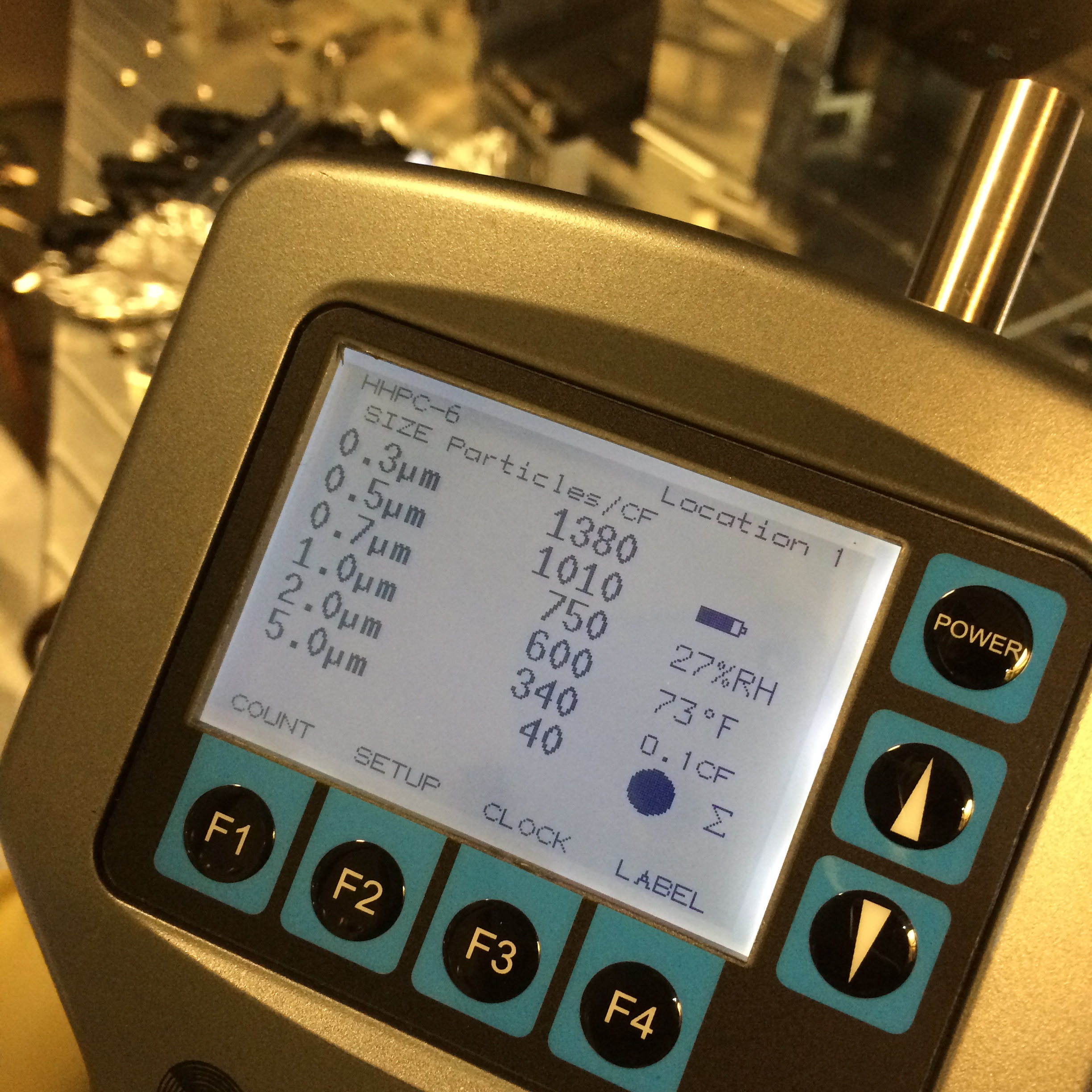
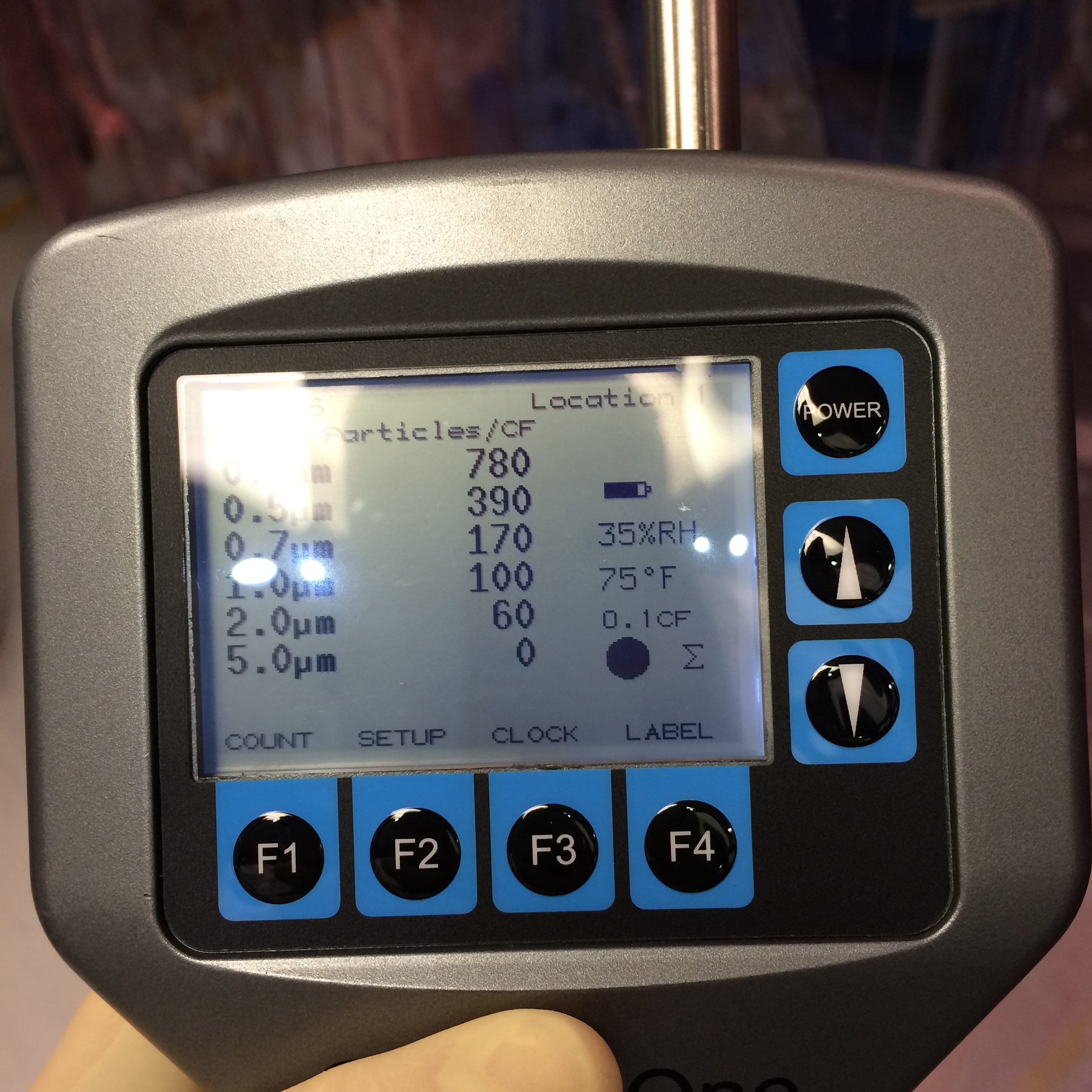
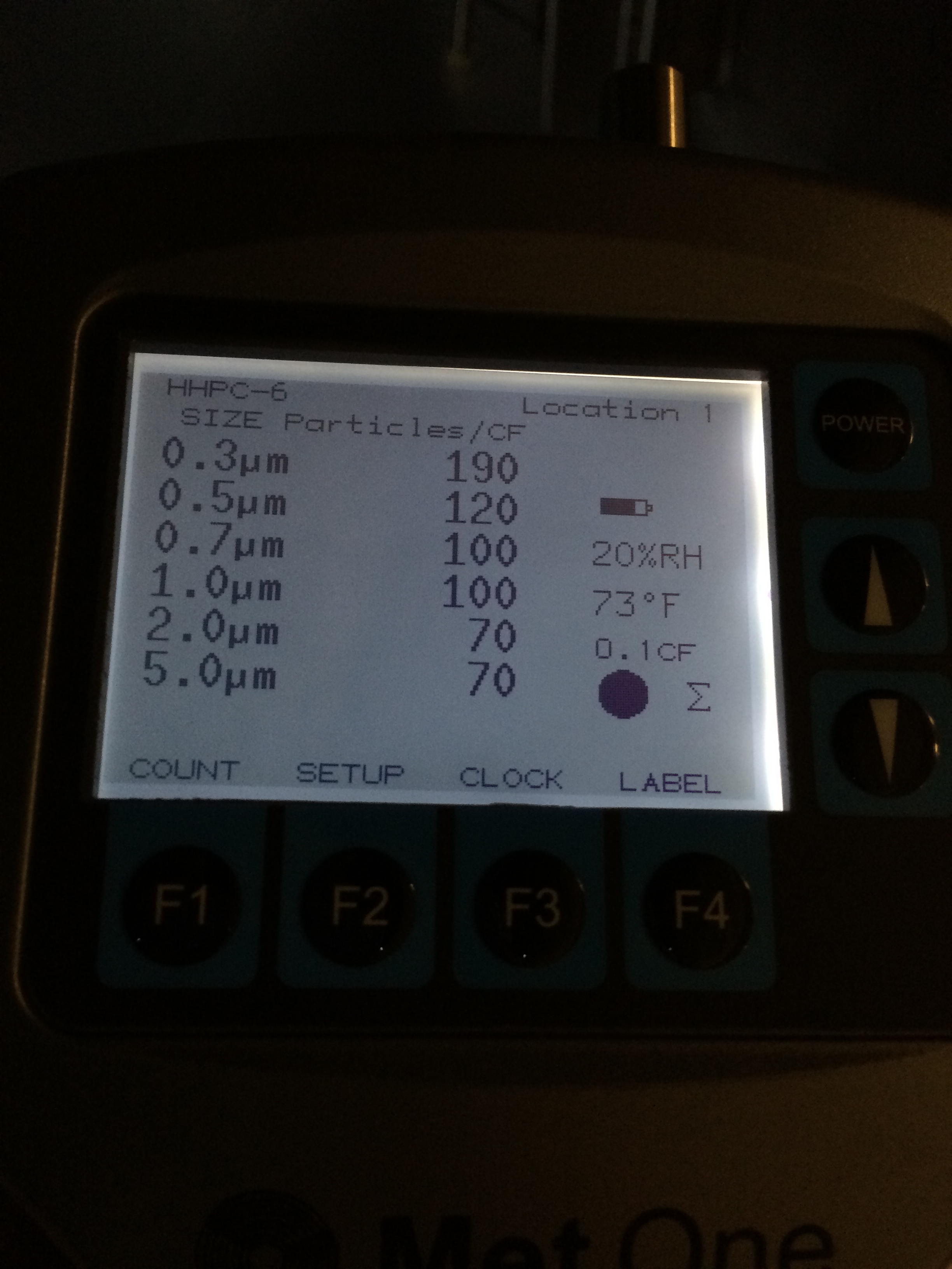
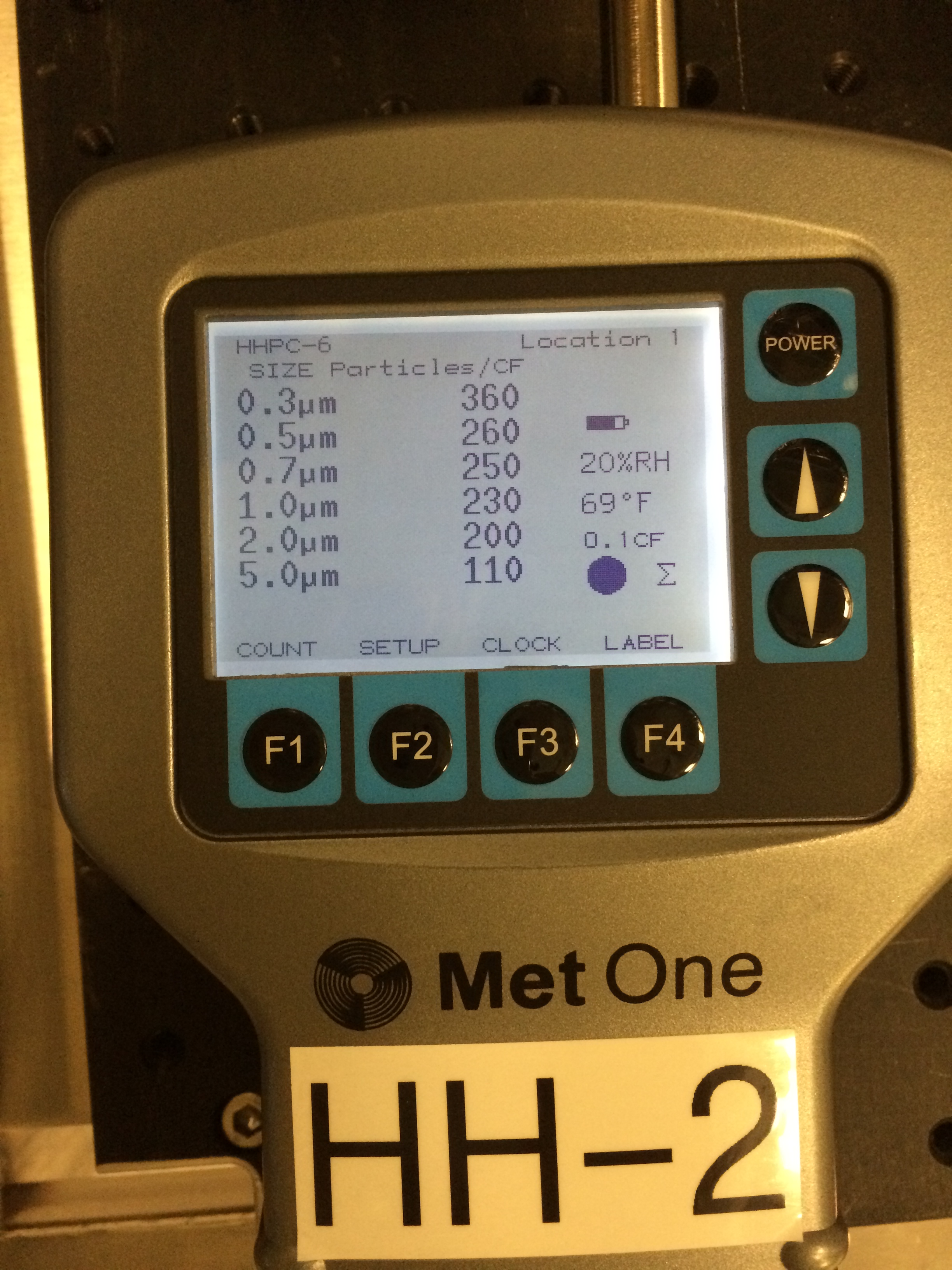
Particle counts after FC spraying was done, taken nearish door ~10 mins after spraying complete, 3 people working in chamber:
0.3um 840
0.5um 430
1.0um 260
Greg also looked at the TCS mirrors in BSC2 while we were there - more from him later I suspect.
We wiped our way out of BSC2 and BSC1.
I then went into BSC3 and wiped the floor.
We broke for lunch.
After lunch we used the N2 gun and removed the FC from the CPx-AR and ITMx-HR. We then alternated blowing on the ITMx-HR and gap between optics for 1 min intervals until each set of surfaces had seen ~5min of N2 deionization at 10psi. I blew the barrels a little while as well.
After unclamping the TM and CP, we set the 1" witness optic and the 3" witness plate on the QUAD SUS and 1 3" WP horizontally on the floor in the center of the chamber. A quick check of TFs in V, P, and T showed a healthy suspension, so we closed the BSC3 door.
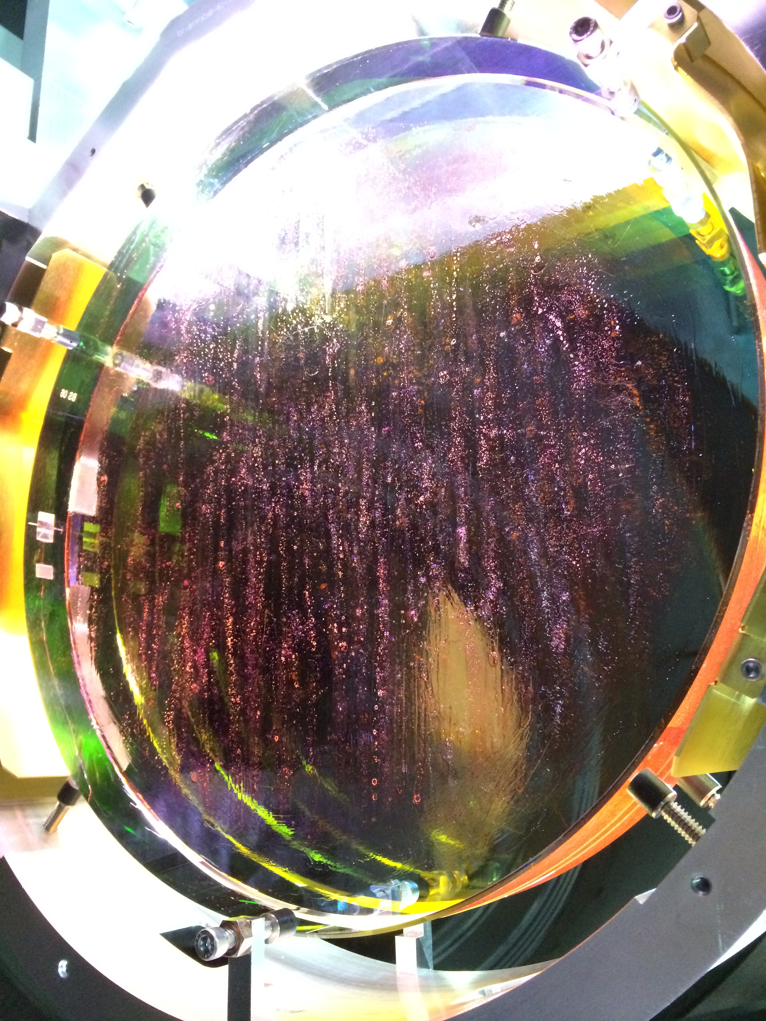
Moving down to BSC2, we pulled the FC on the BS-AR. It tore across the top and then as we pulled it down across the optic it left 2 ~2mm chunks of FC in the center ~4 inches of the optic. We determined that we would need to respray clean this surface (phiszzll) so we aborted the BSC2 and BSC1 chamber closeout.
We pulled the BS-HR FC to make sure it wouldn't leave anything else either.
Jim locked the BSC2 ISI again and we mounted the FC spray cone to respray FC on the BS-AR and HR surfaces. We reinforced the edges of the sheets with paint-on FC as usual. Tomorrow we will reattempt to pull the BS and ITMx FC sheets and move on to close these chambers.

 Unfortunately the mass of the FC came in under the expected mass and below the allowed variation; if you look at E1200791 the allowed variation of the FC mass is 0.159 g, which results in a low end mass expectation of 2.955 g, not the 2.8 g I measured.
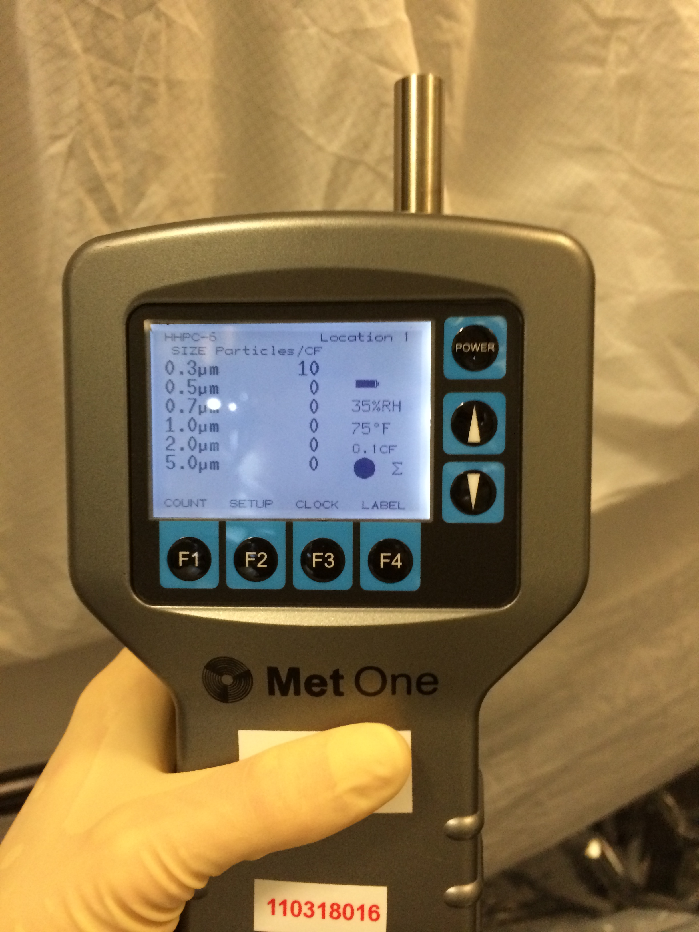
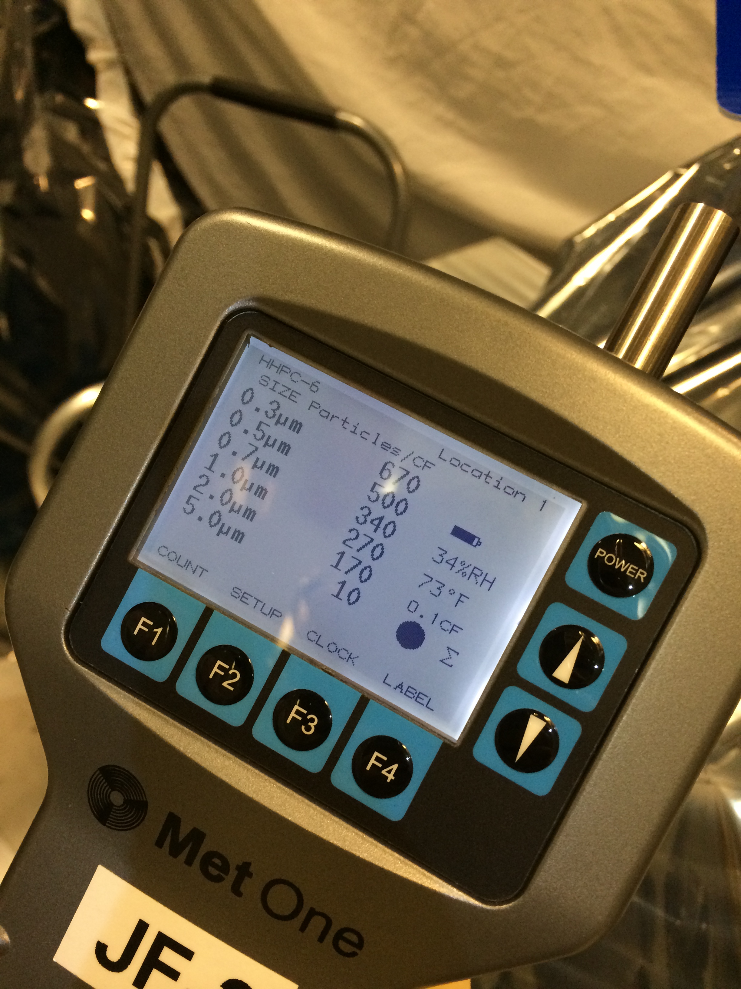
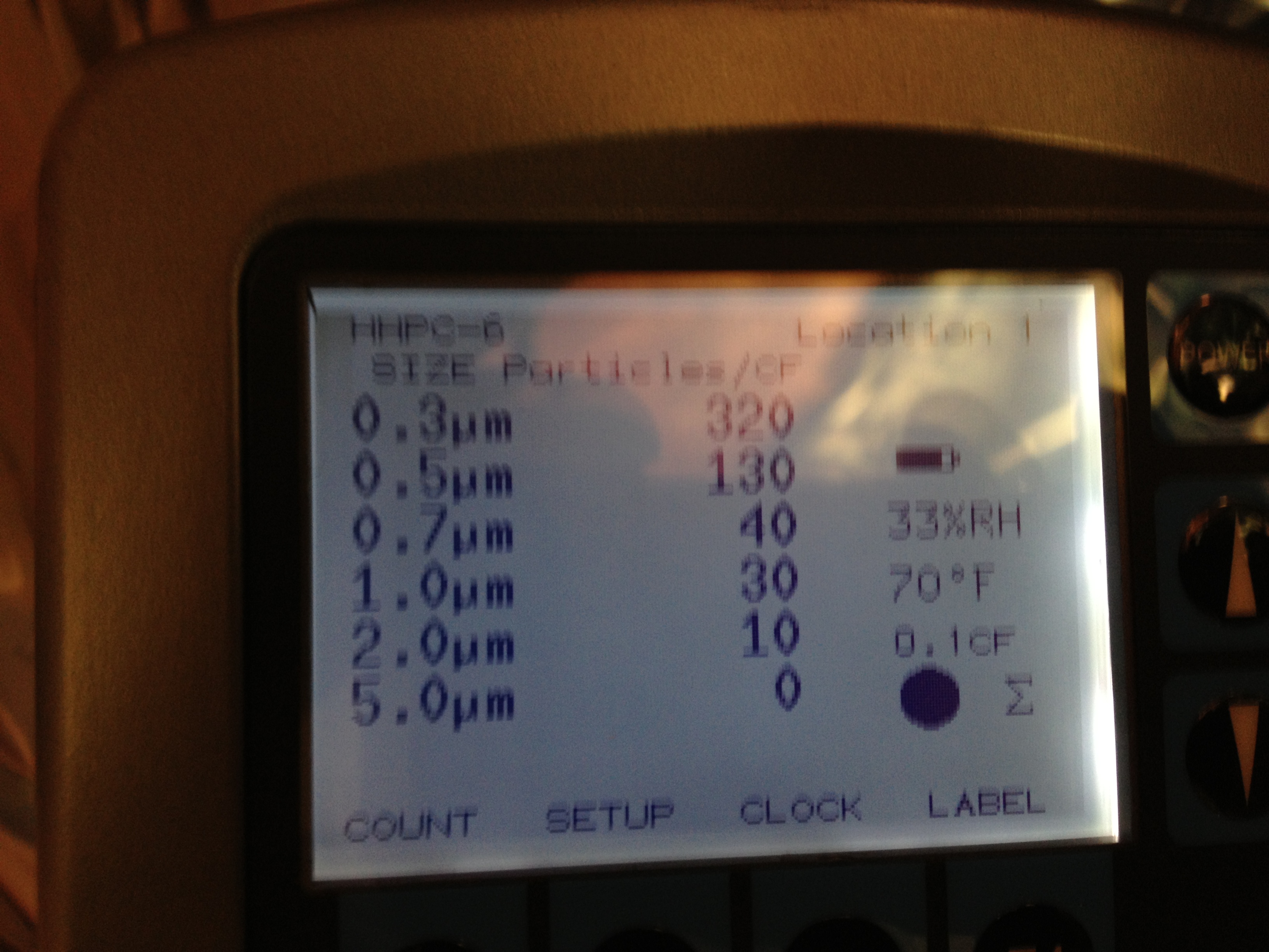
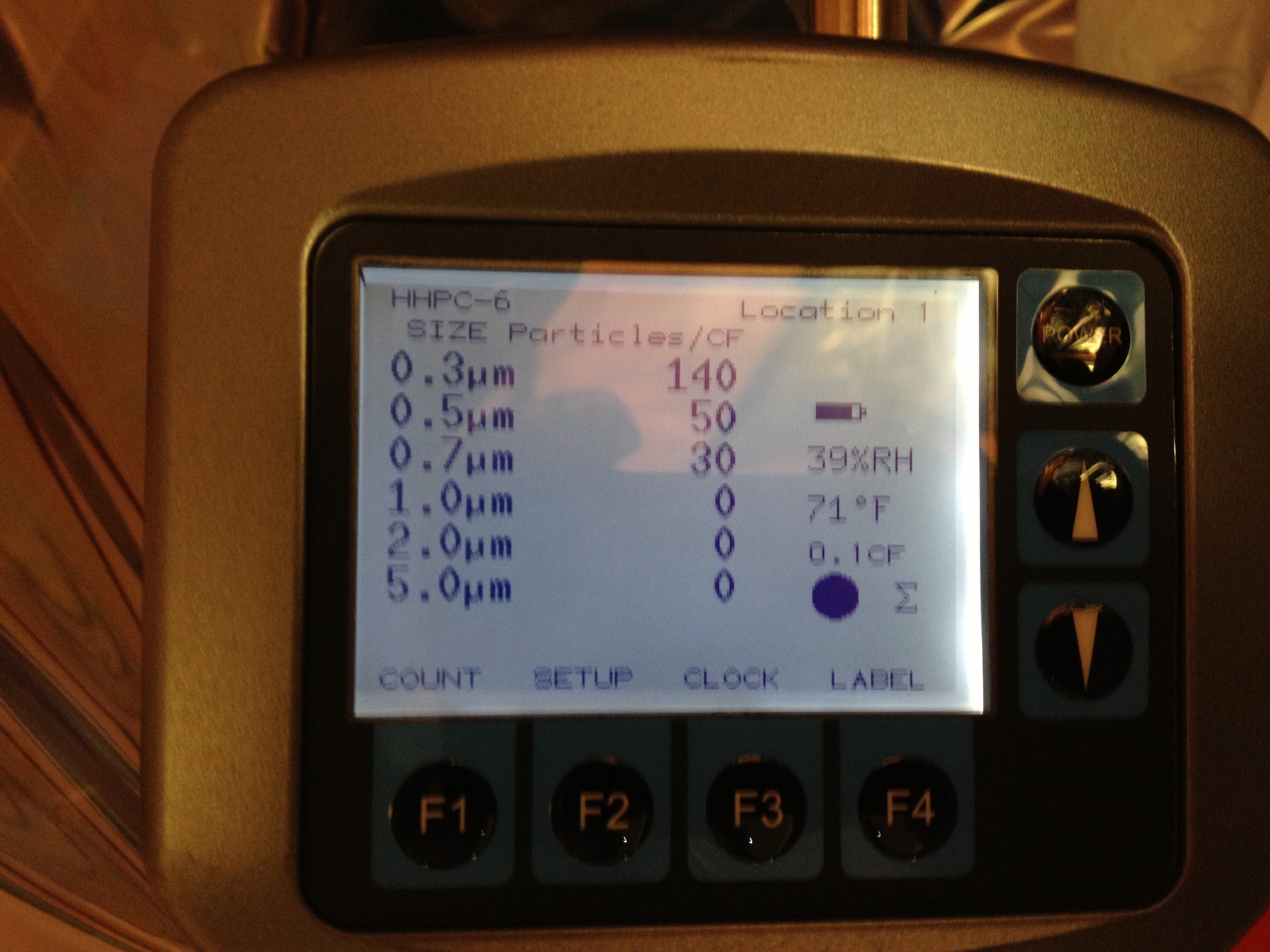
Particle count measurements were taken in BSC 1 and 2 numerous times during the ~2 hours of First Contact removal and chamber closeout on Friday. First Contact was pulled on the BS HR and AR surfaces around 12:30pm. FC was pulled on the ITMy HR, CP-AR around 1:45pm. BSC1 door was attached to chamber around 2:30.
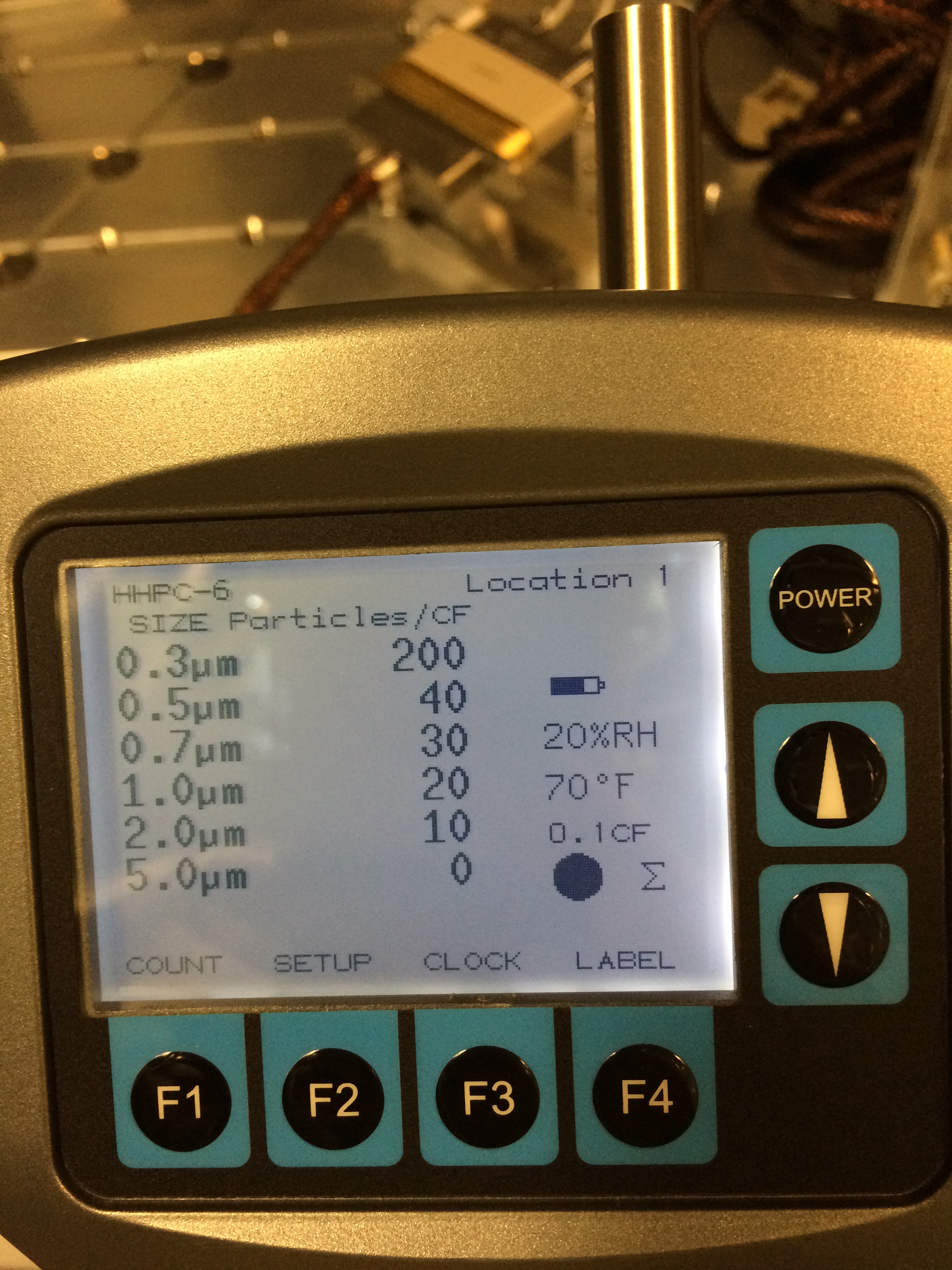
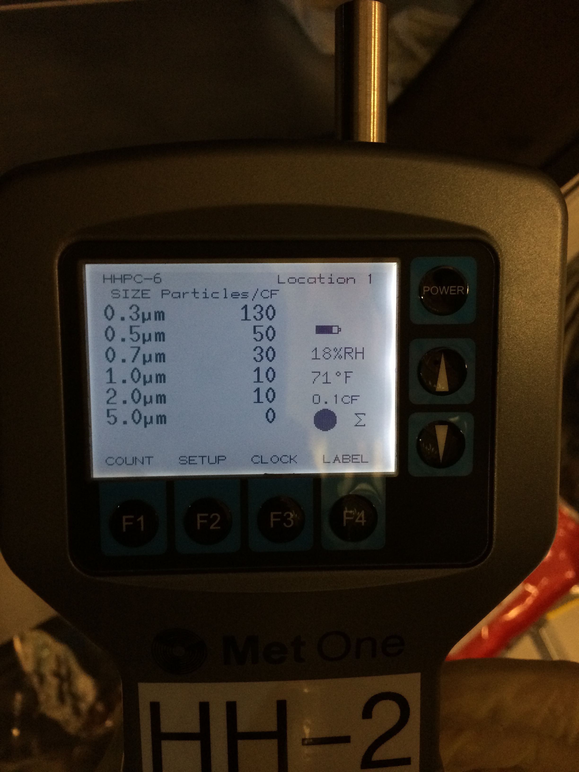
Counts were always around:
0.3um ~200
0.5um ~60