Gary T, Danny S, Matt H, Stuart A
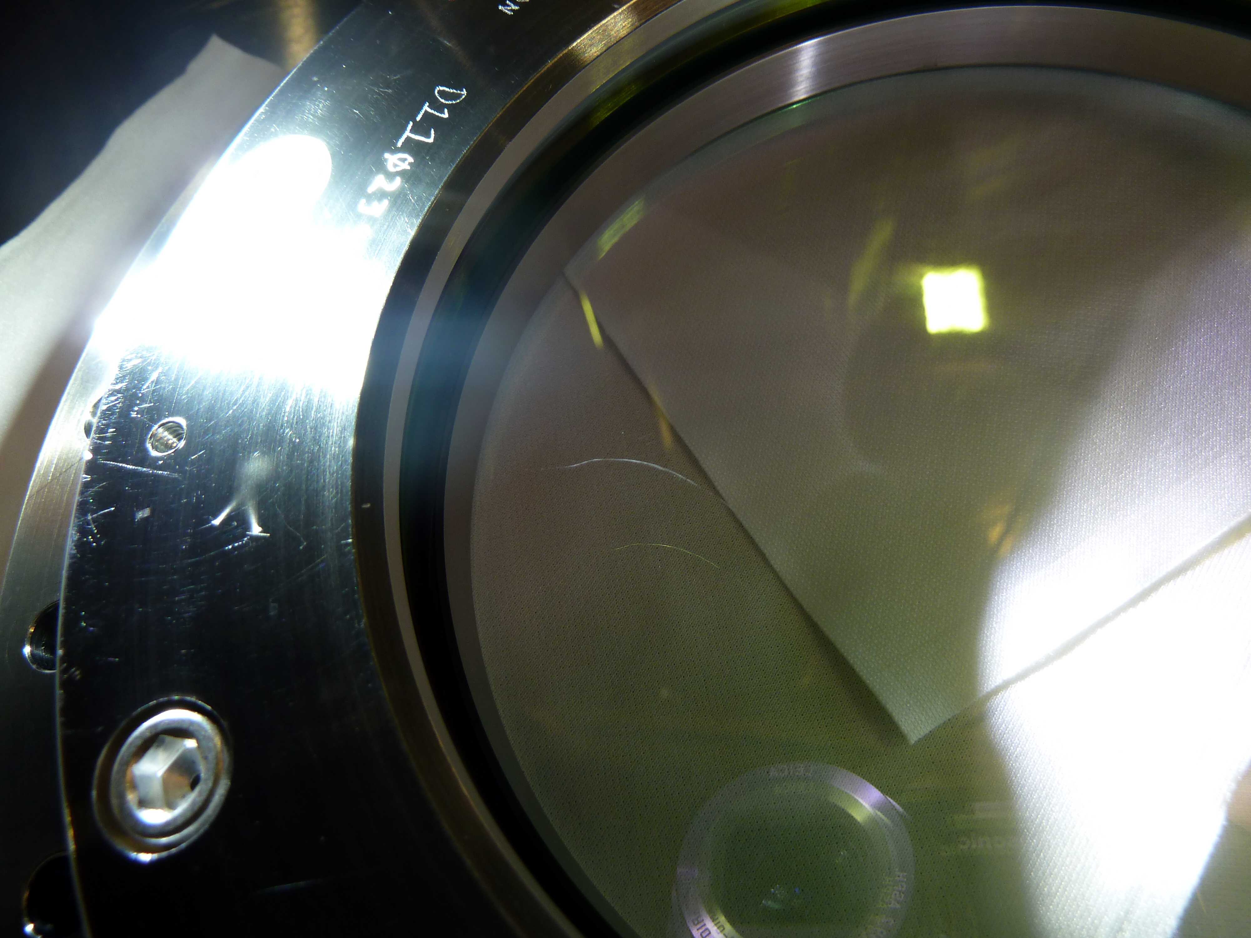
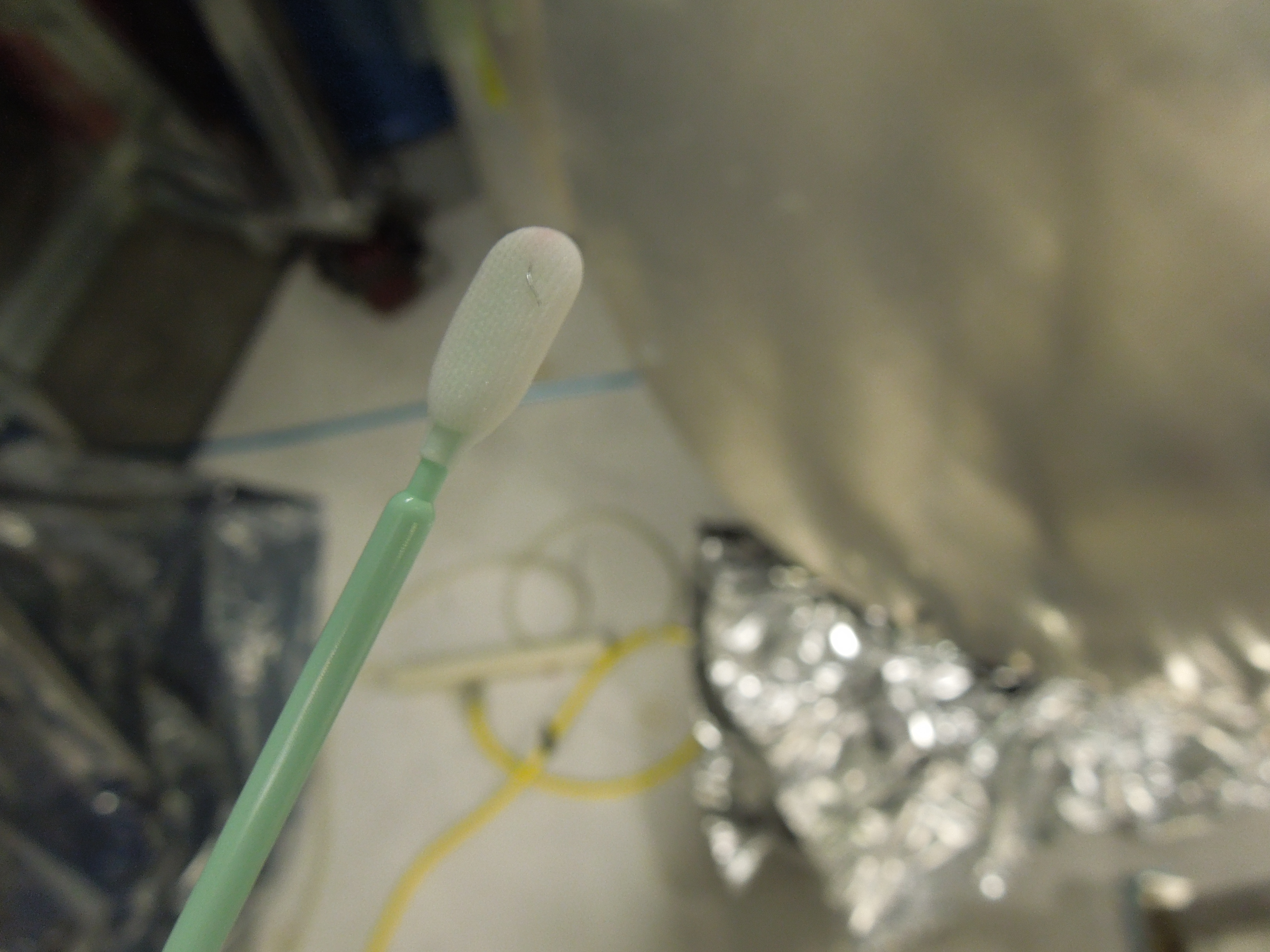
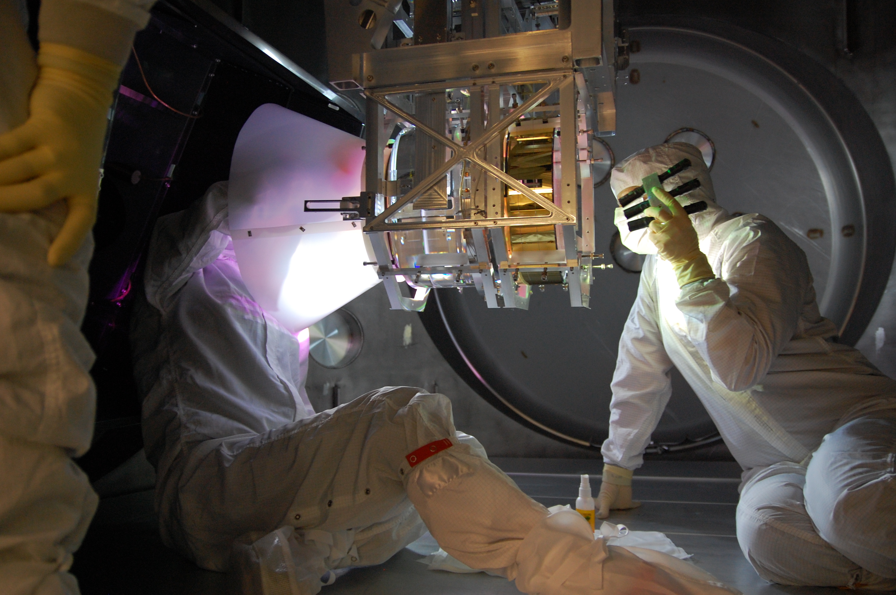
Well was a frustrating day today. We removed the 3 wafers (2 horizontal and 1 vertical) and the vertical optic that was still in chamber, and also put in a 1inch optic (still with its first contact). We gave everything a wipe and then vacuumed everything then wiped again.
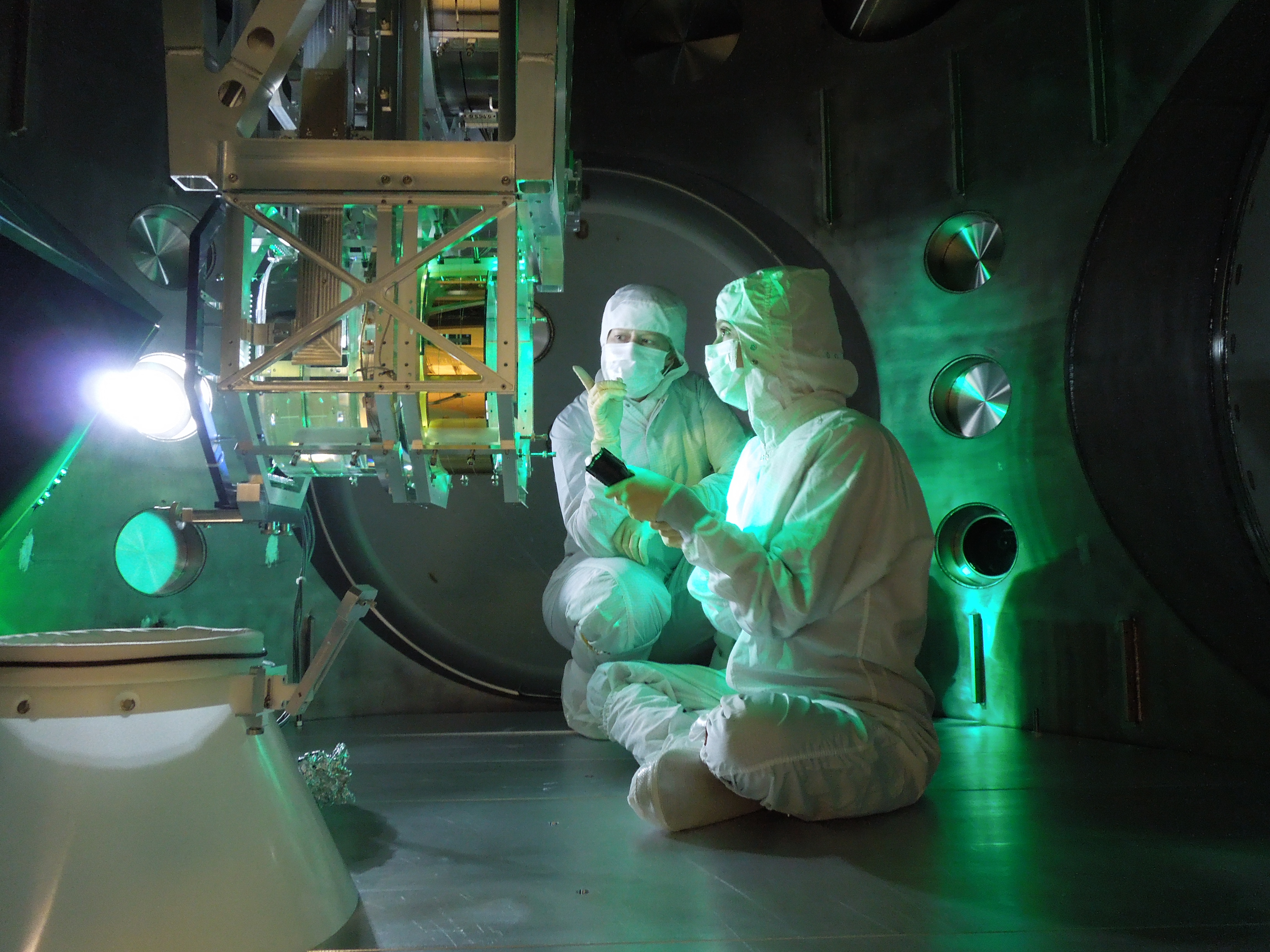
Keita asked us to centre the BOSEMs on the TMS with the offsets applied and the TMS damped. And so this is what was done. Keita had a look at what we had done and okayed it.
Counts were still really high after vacuuming so we broke for lunch and during that time we got Jim to unlock the ISI. We wiped again and counts okay, so thought we could start the closing process and started with blowing off quickly the TMS. This put the counts up highish, but figured we would try blowing between the two optics for the 5 minutes agreed upon with Mike L and Norna, let counts settle low and then pull FC. Unfortunately we could never get the counts to go lower than say 400-500 (for 0.3um) with people not moving in the chamber for ~30 mins, and as soon as they did the counts would go up into the 900's-1300's (for 0.3um). We tried wiping floor yet again and couldnt get counts lower. Note: we even have a new BSC door cover on.
So I talked to Calum and we decided that we will just have to go with as low as counts as we can get and just log the counts we have whilst doing the closeout tasks. As its getting on today we decided to stop here, Jeff B is going to come in early and wipe the chamber again one more time...this should give time for everything to settle and then we wil ljsut go for broke with pulling this. I dont think we can get this much better in the near term. I think shows how important that we need to do cleaning on the go everytime anyone is in there.. We are very confident we can get everything done in a couple hours after morning meeting tomorrow though and then that end is done.
PS..Gerado just came and talked ot me and the "stuff" we see on the middle viewport of eastern door is on the middle. We we will paint FC on that tomorrow as well and pull that (before we pull FC on optics)
Quick timeline
Particle counts
In cleanroom start of day
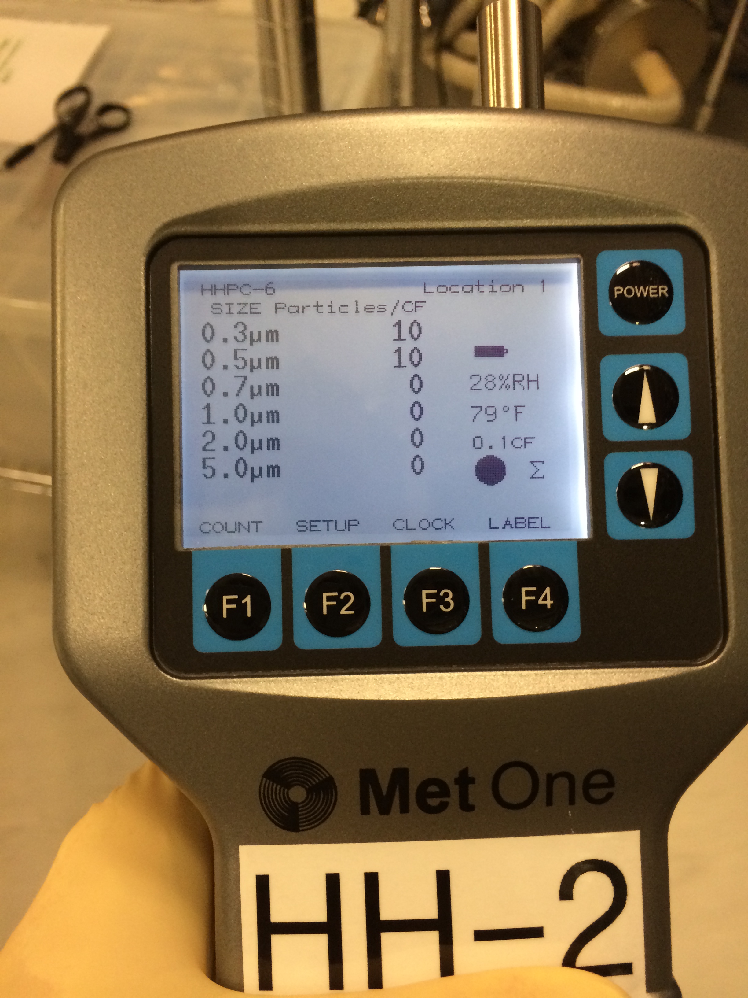
All counts zero (see pic 1)
In chamber start of day
All counts zero (see pic2)
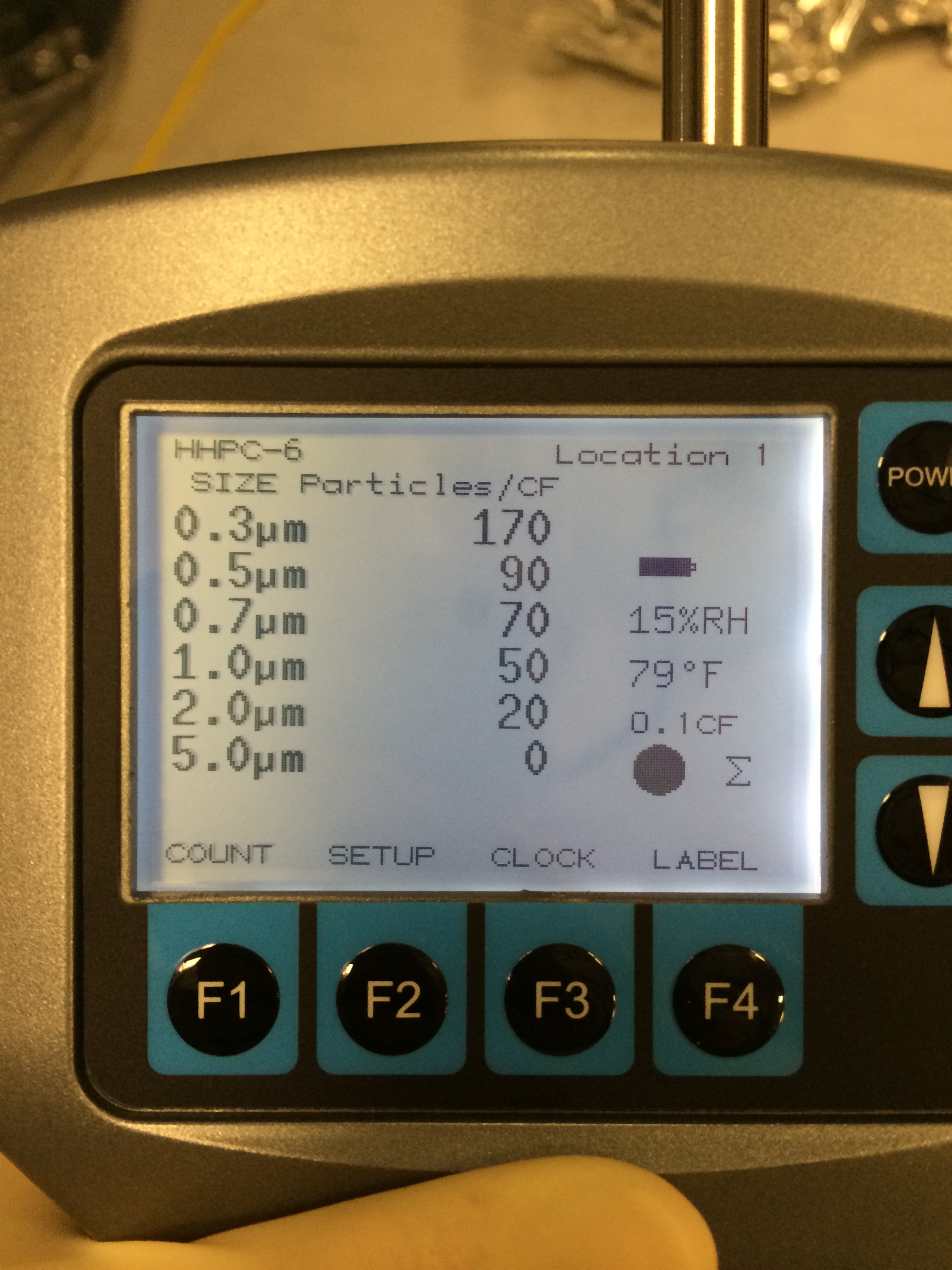
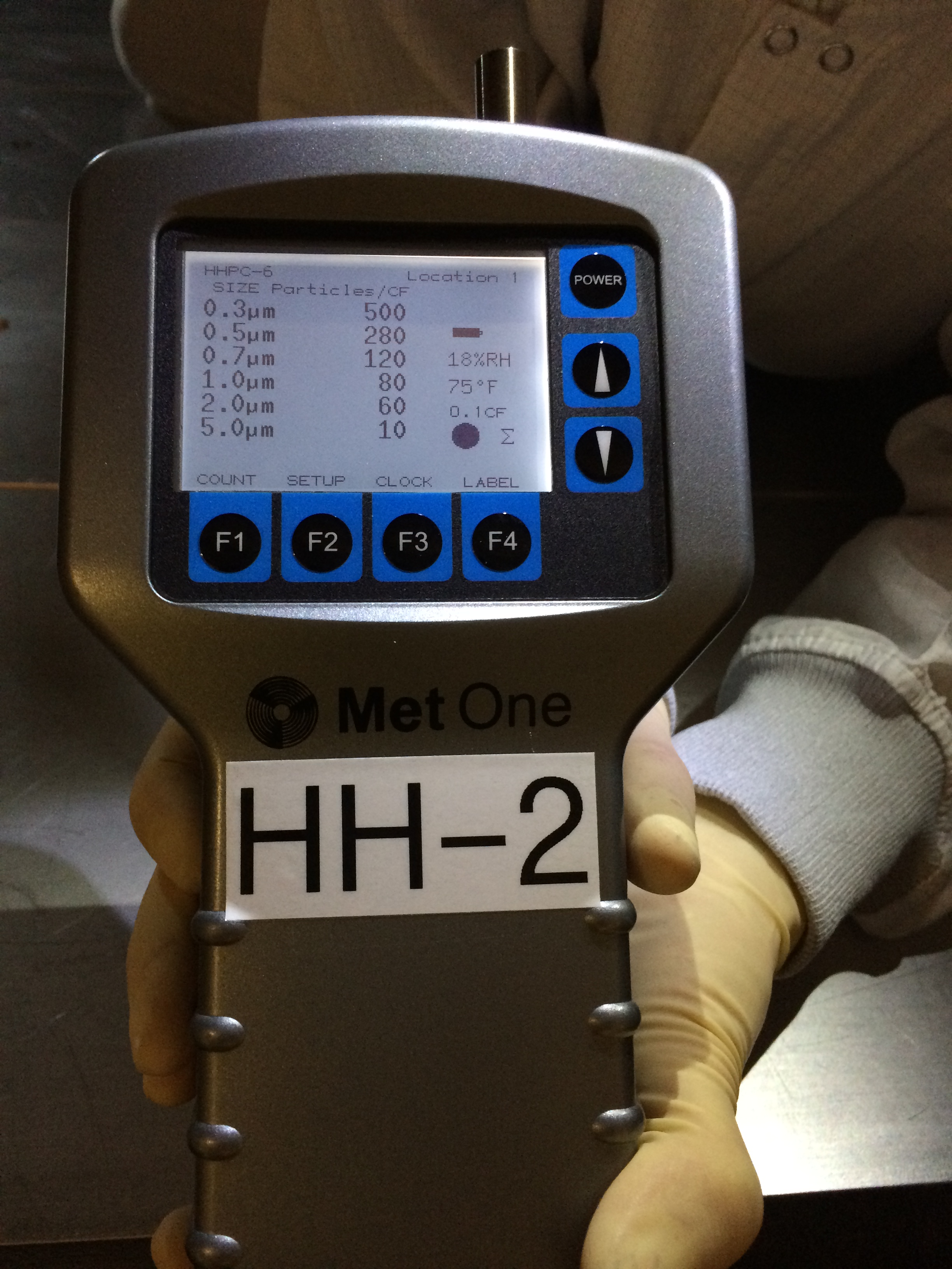
In chamber as removing wafers (see pic 3)
0.3um.....950 counts
0.5um....400 counts
0.7um....270 counts
1.0um....200 counts
2.0um..140 counts
5.0um...60 counts
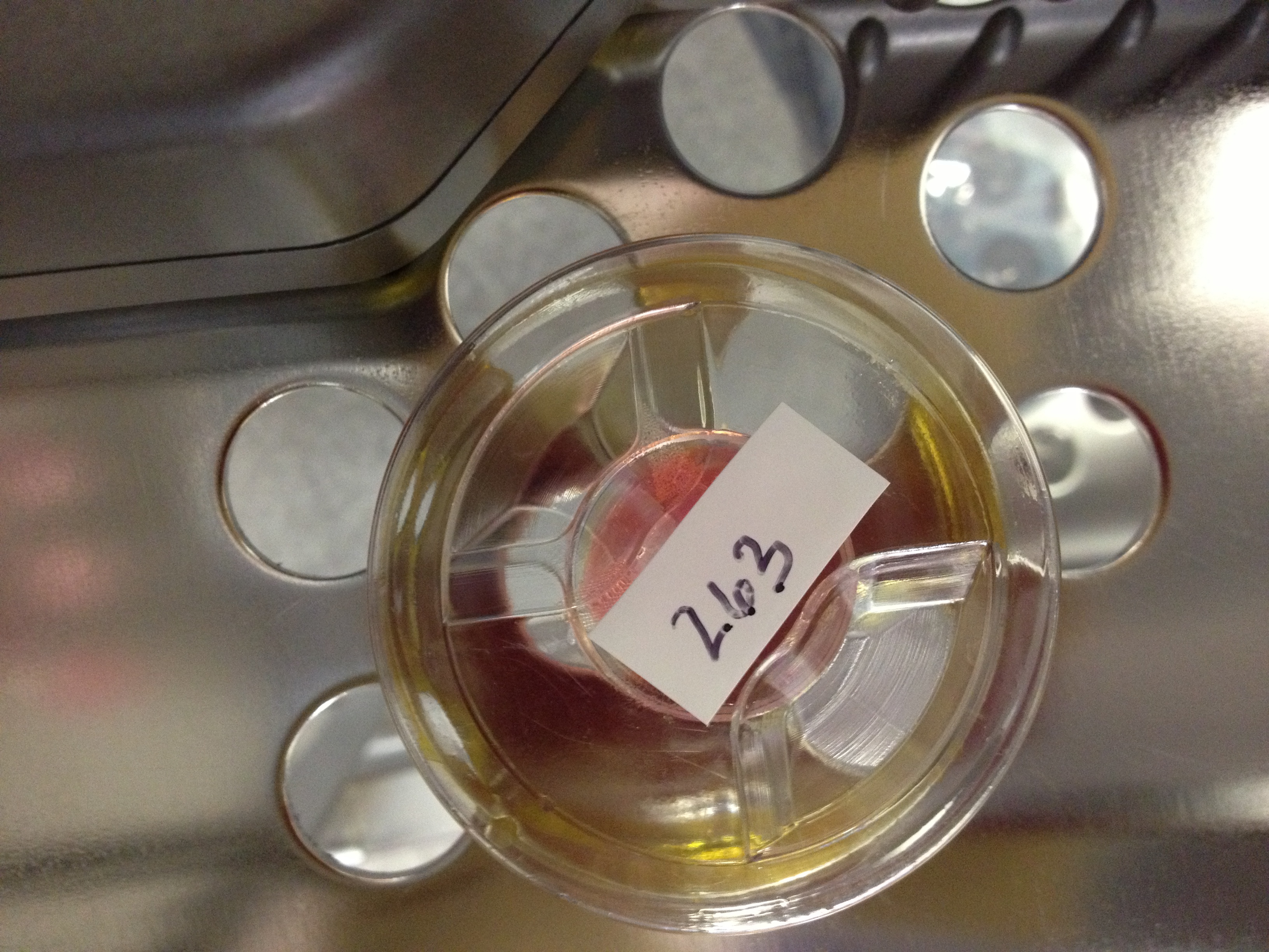
Pic 4....S/N of the optic put into X end station
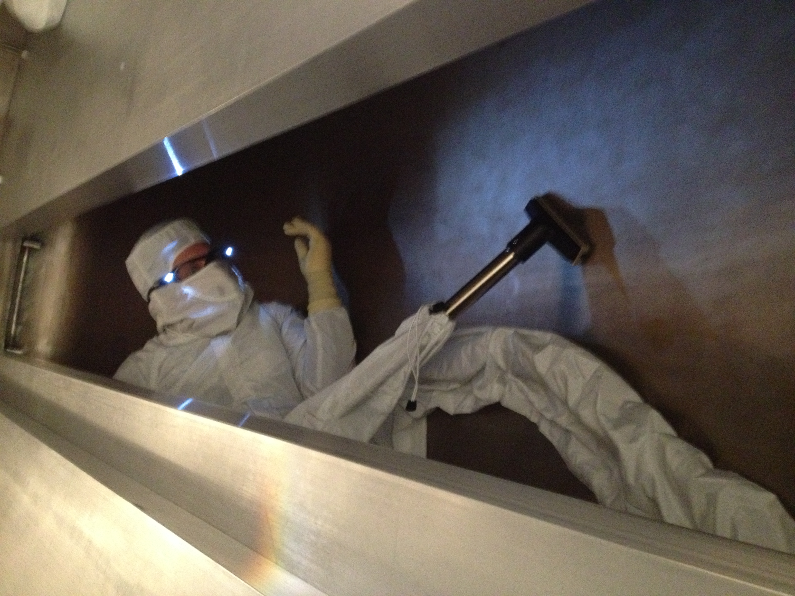
Pic 5...vacuuming under the floor boards
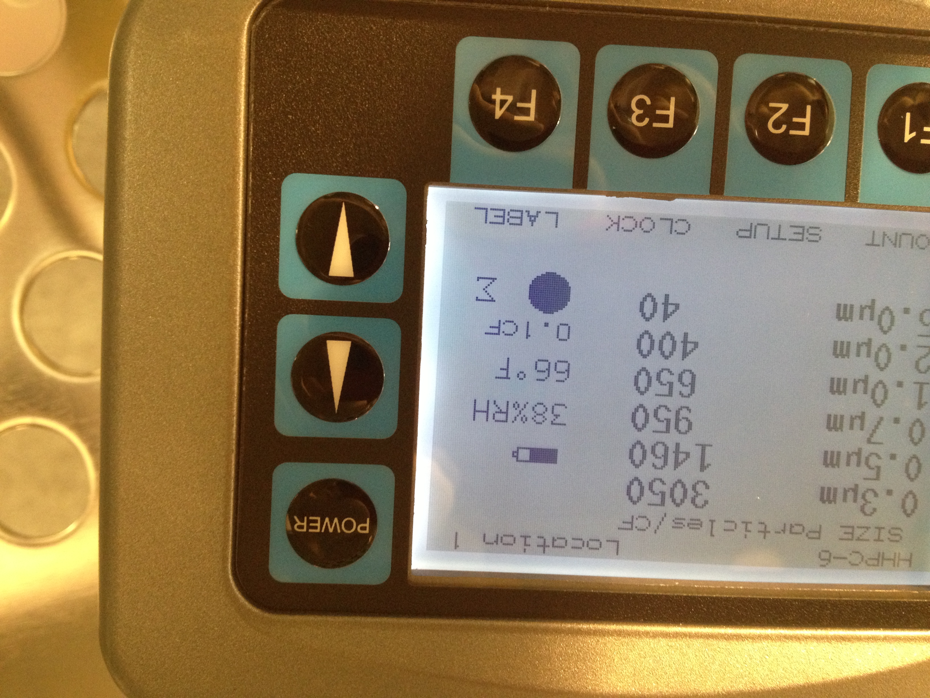
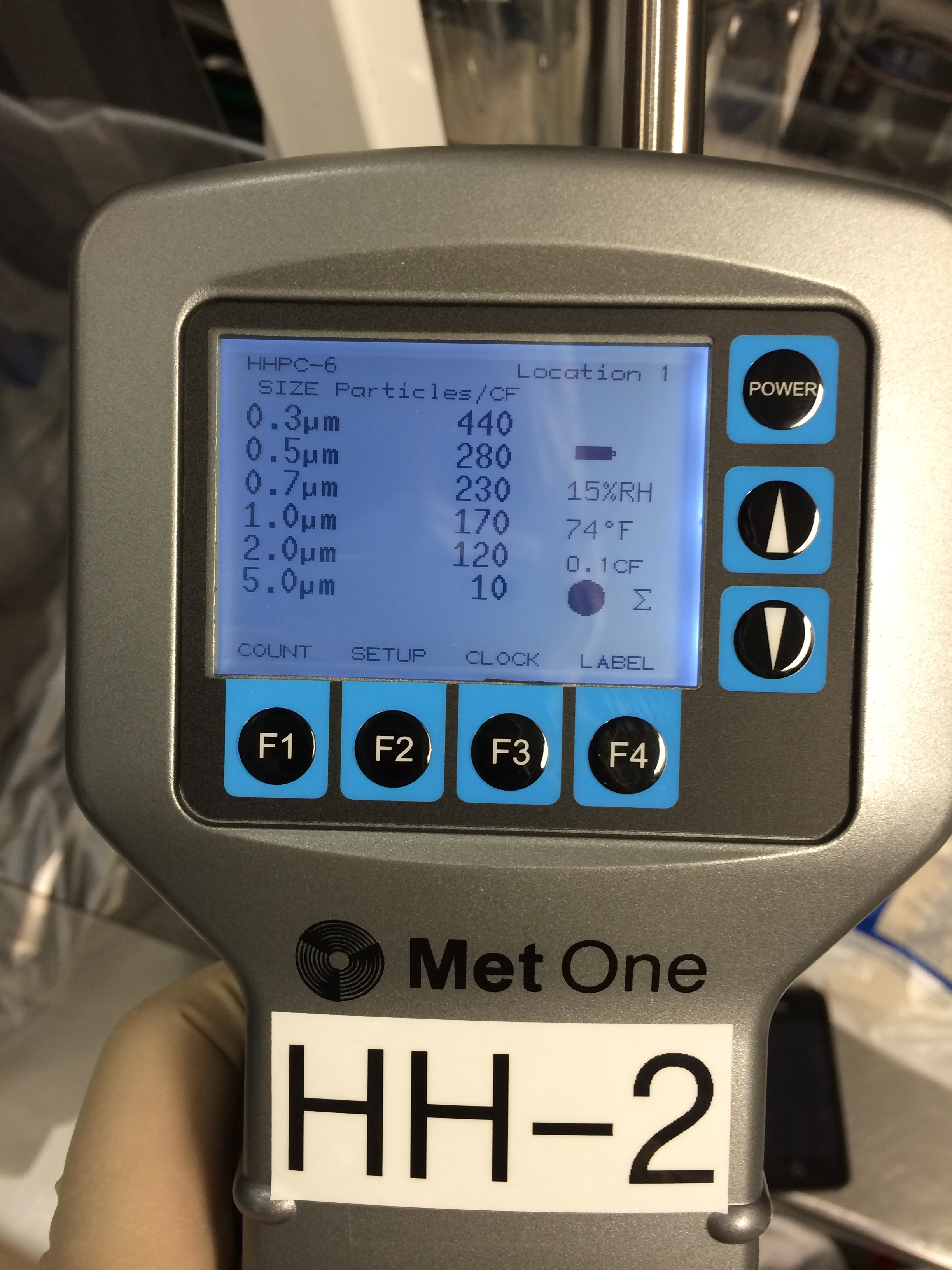
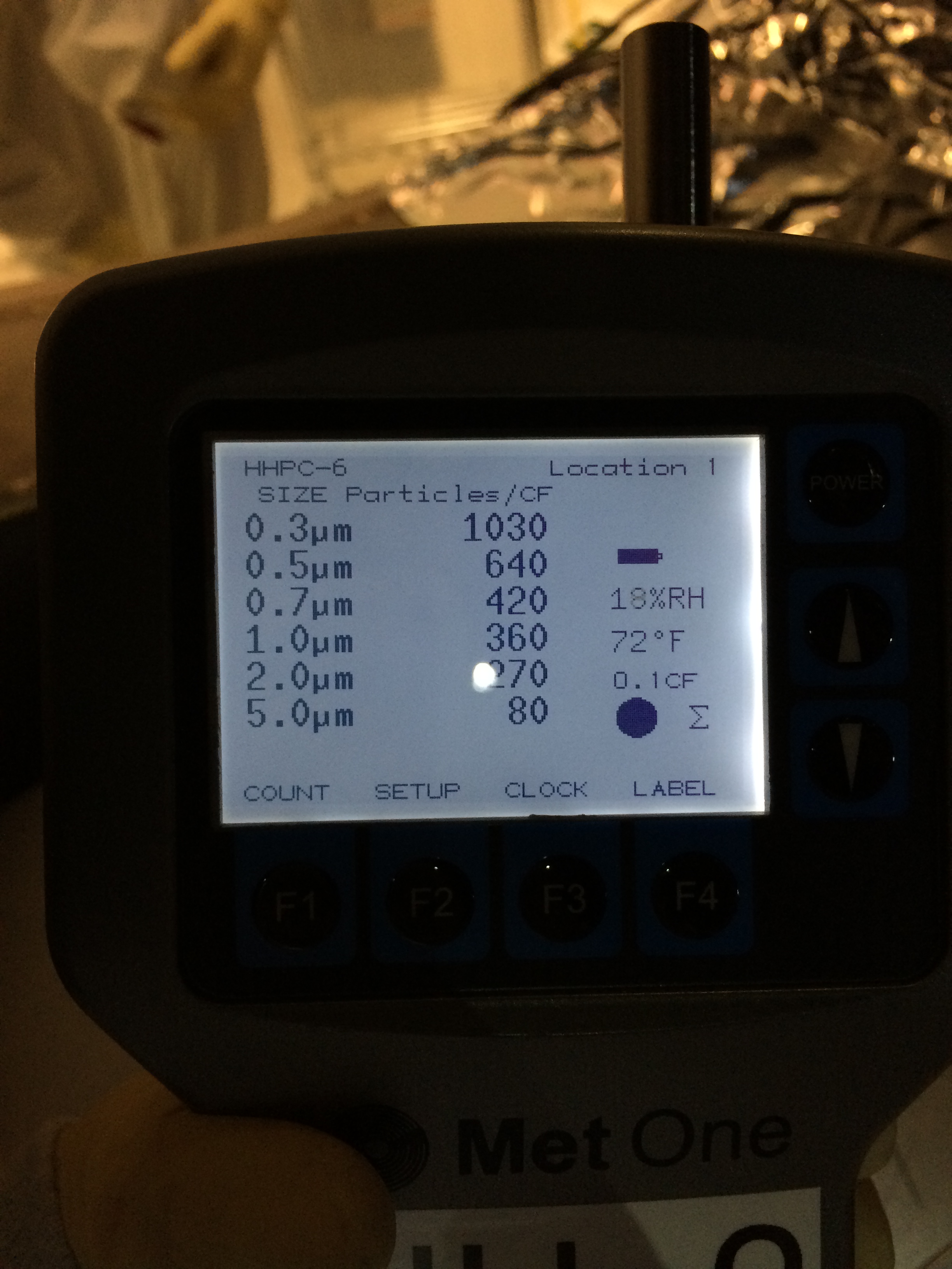
In chamber during vacuuming (see pic 6)
0.3um....3050 counts
0.5um....1460 counts
0.7um...950 counts
1.0um....650 counts
2.0 um...400 counts
5.0 um....40 counts
In chamber exiting for lunch..to let counts settle (see pic 7)
0.3um....2310 counts
0.5um...1030 counts
0.7um....570 counts
1.0um...340 cunts
2.0um...240 counts
5.0um....60 counts
1.30pm...in cleanroom after lunch
All counts zero
1.32pm..In chamber after lunch (see pic8)
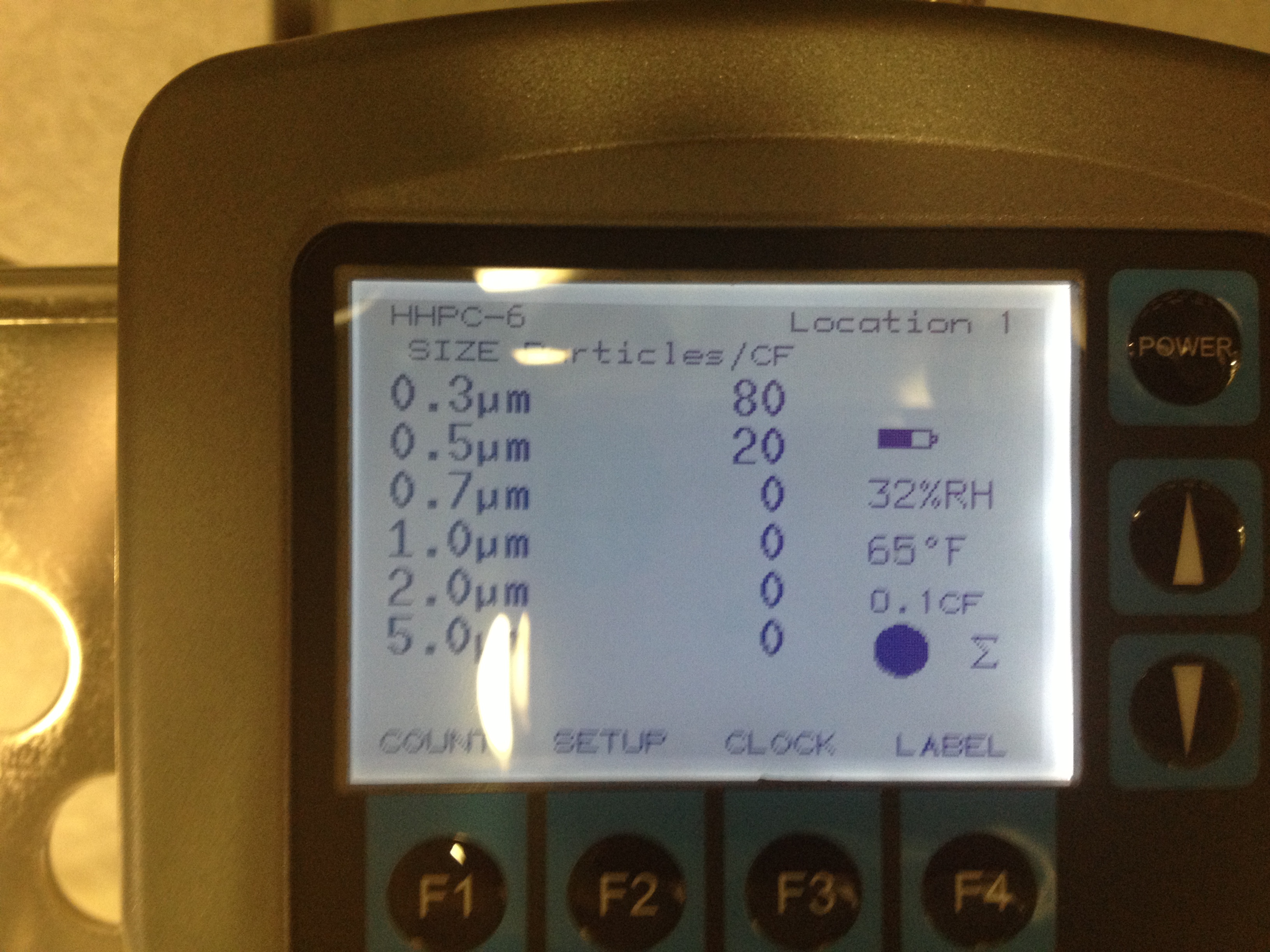
0.3um...80 counts
0.5um...20 counts
rest zero
1:44pm..blowing TMS optics
1:49pm..finished blowing TMSoptics
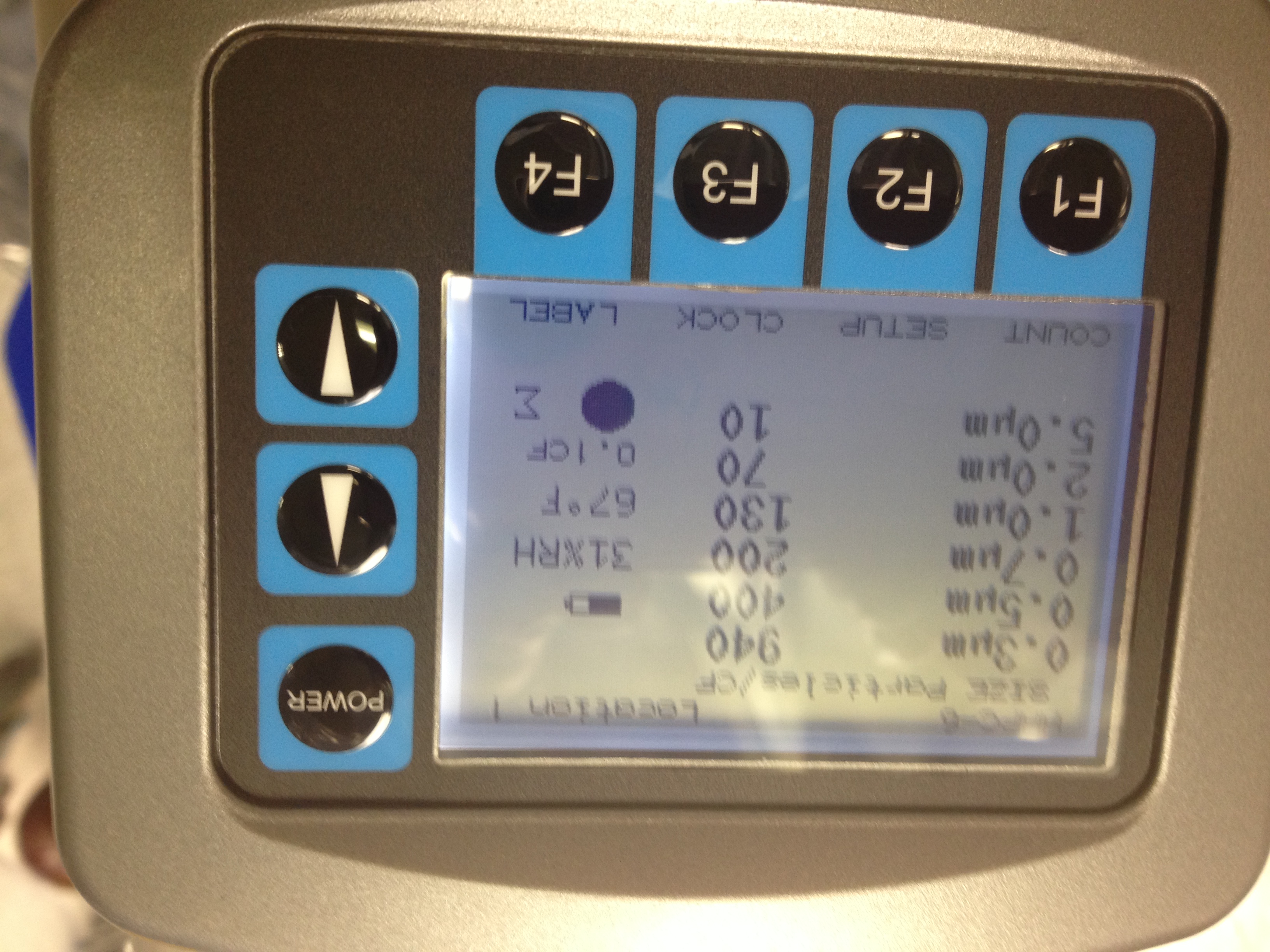
Particle counts (see pic 9)
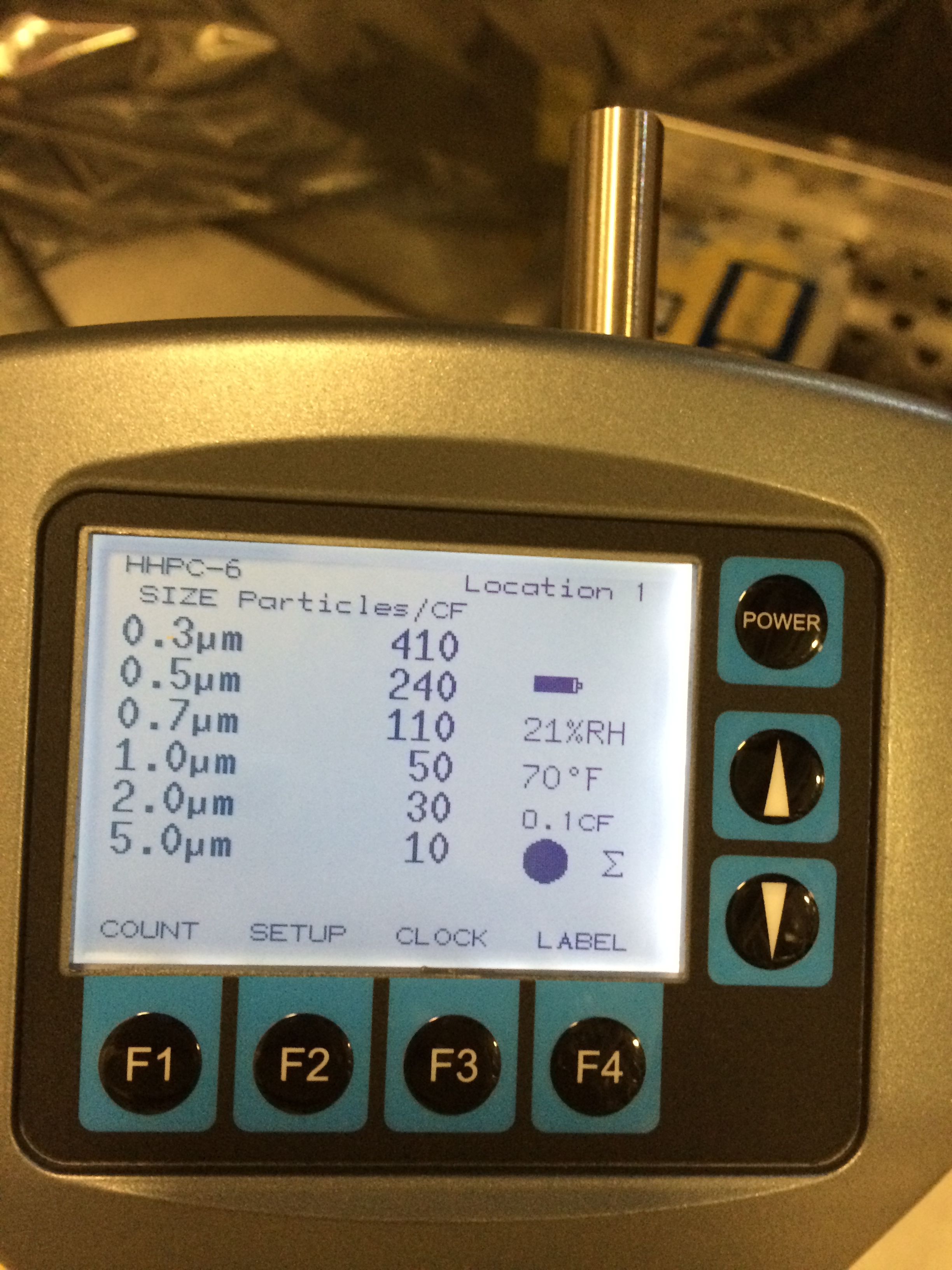
0.3um...940 counts
0.5um...400 counts
0.7um...200 counts
1.0um...130 counts
2.0um...70 counts
5.0um..10 counts
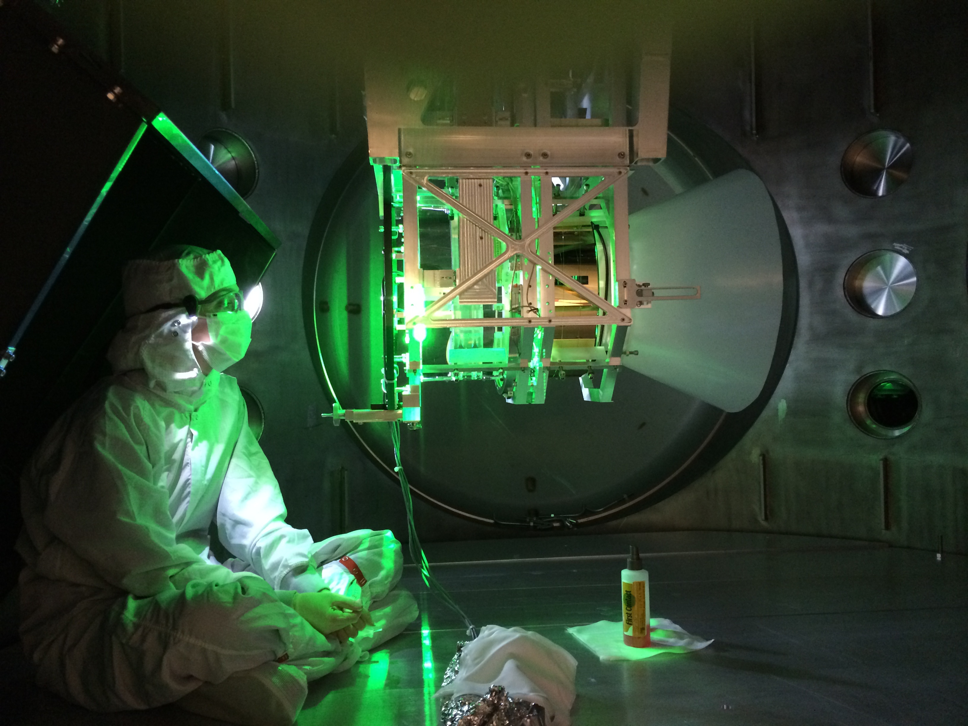
1:50pm...blowing between two optics for 5 mins
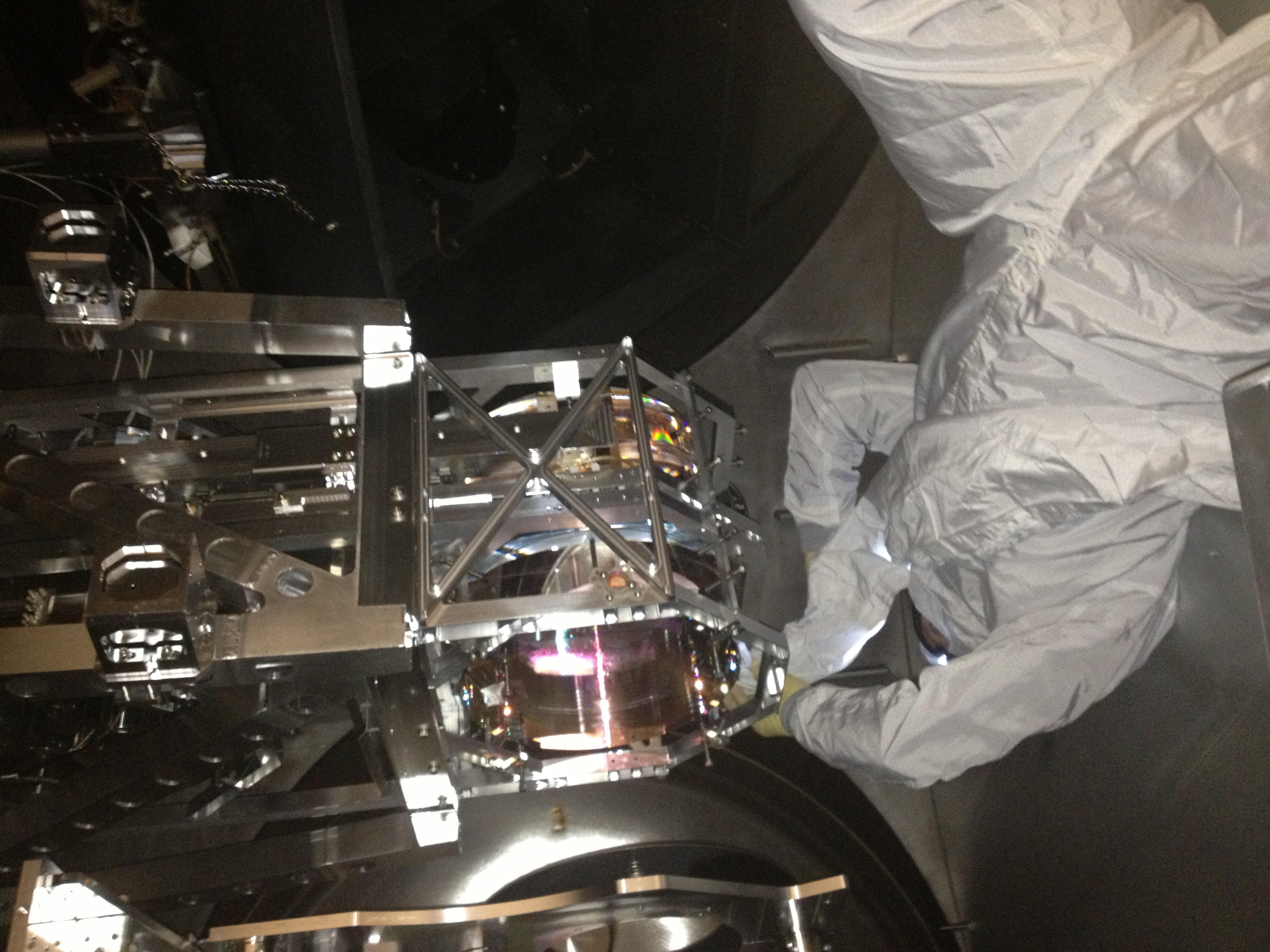
Pic 10...Gary blowing between optics
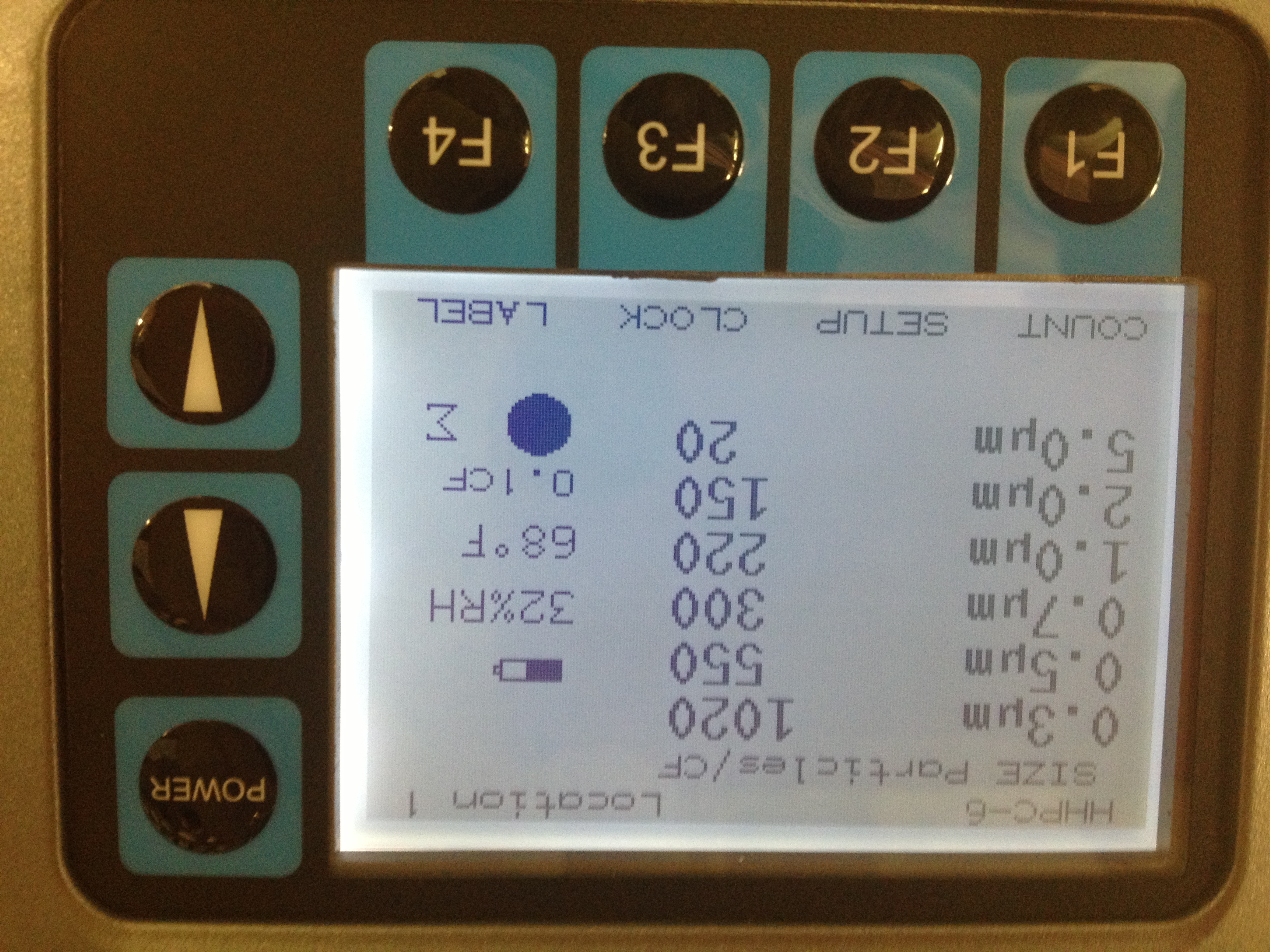
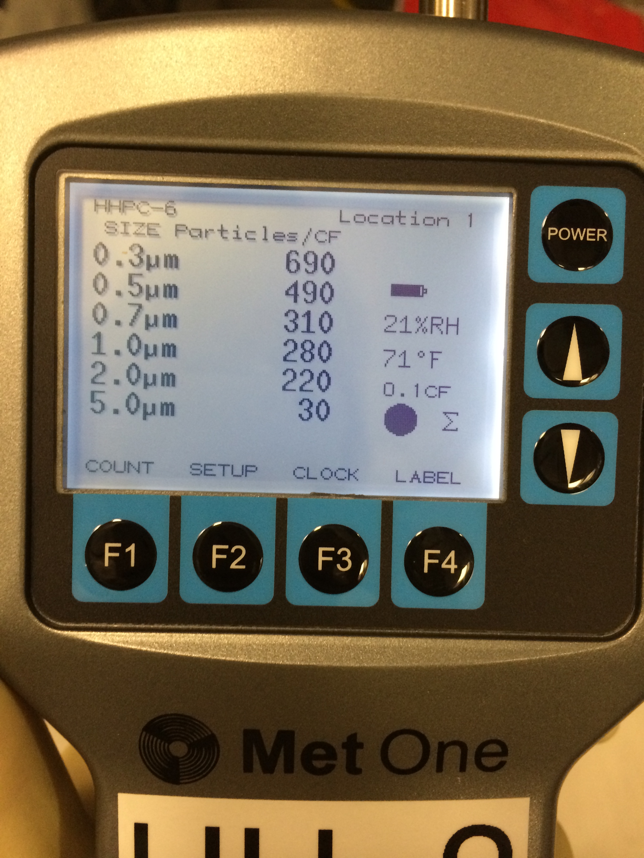
Particle counts end of blowing (see pic 11)
0.3um....1020 counts
0.5um...550 counts
0.7um...300 counts
1.0um...220 counts
2.0um....150 counts
5.0 um...20 counts
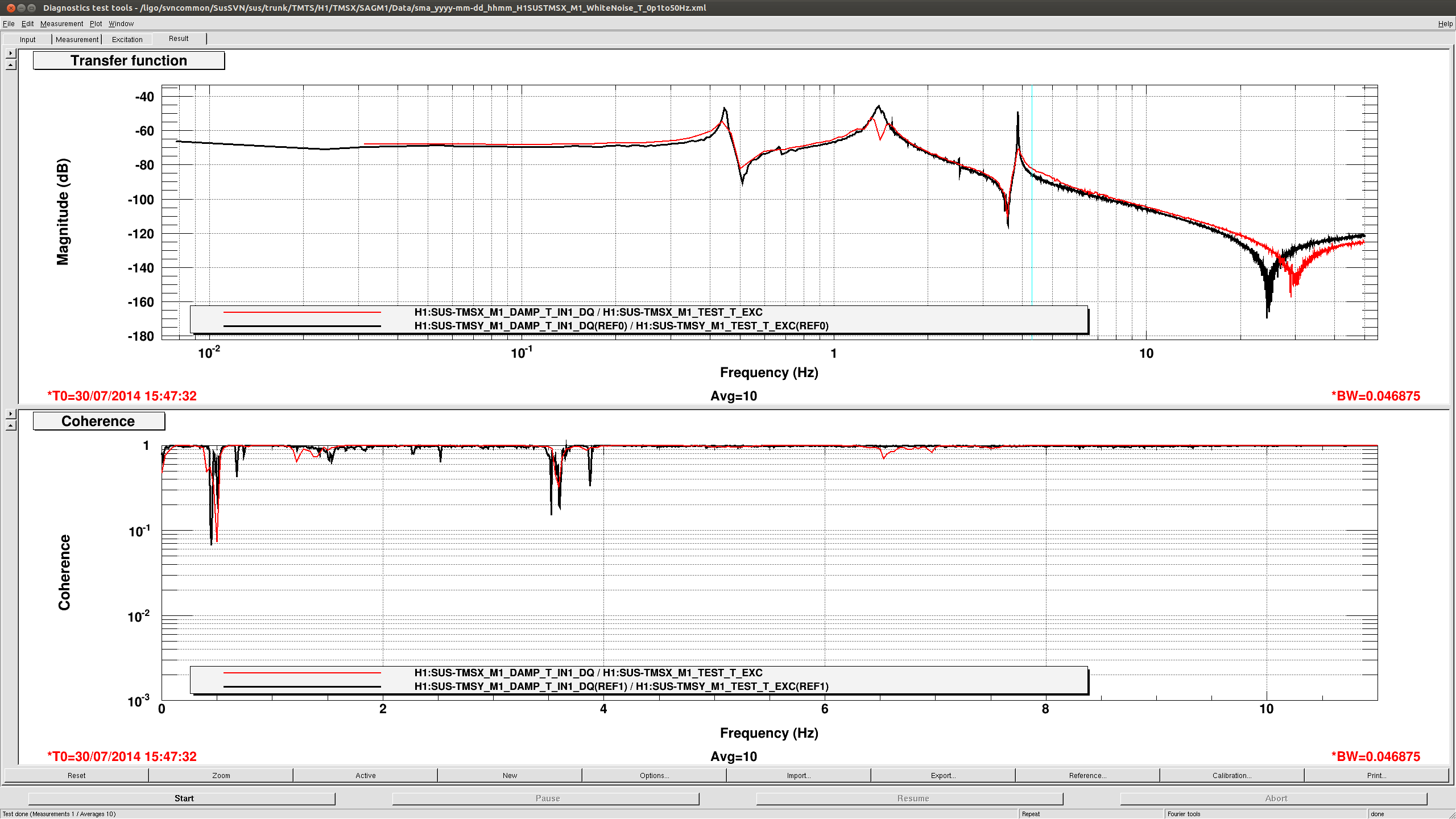
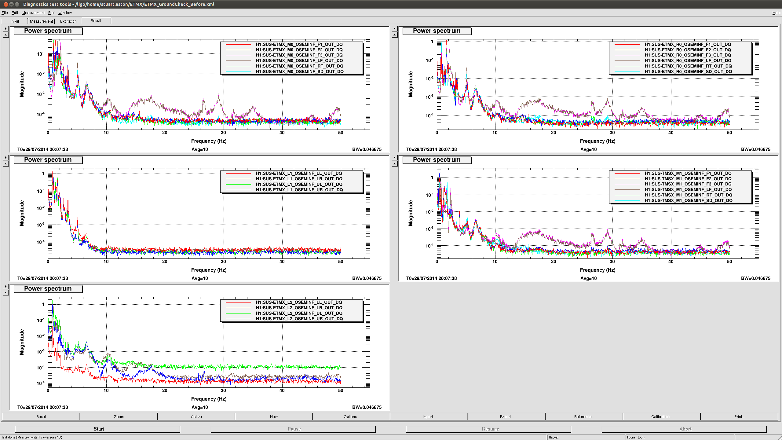
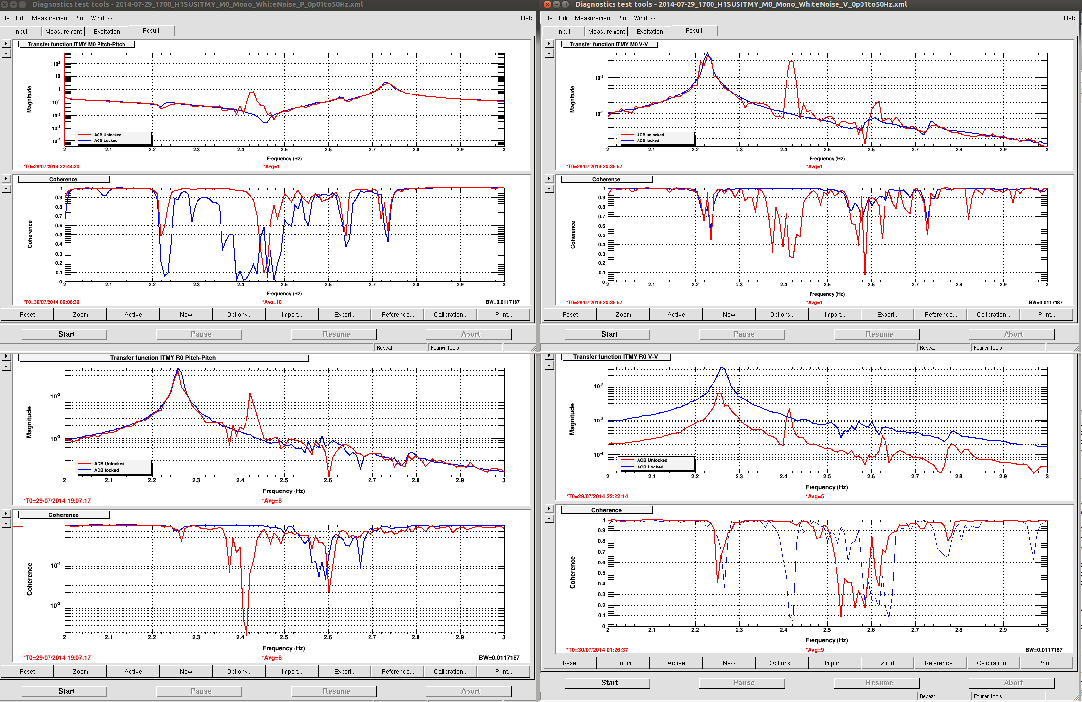
1.58pm...starting TMS TF;s
2.15pm..counts still in 400-500's for 0,3um range
2.40pm...talked to Calum about Particle counts....Will go with lowest we have seen (400-500 count range) to be our new "zero" for this chamber this time
2.45pm...counts in 0.3um range back to 600-800 range with little to no movement by guys in chamber
2.52pm..wiping floor again
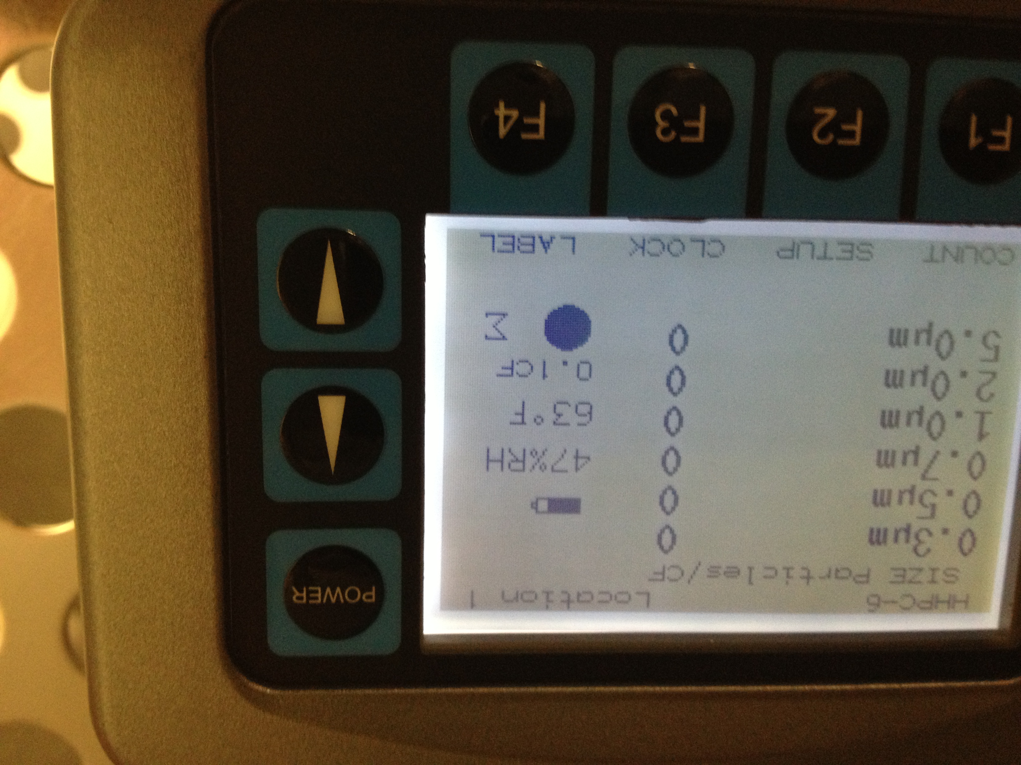
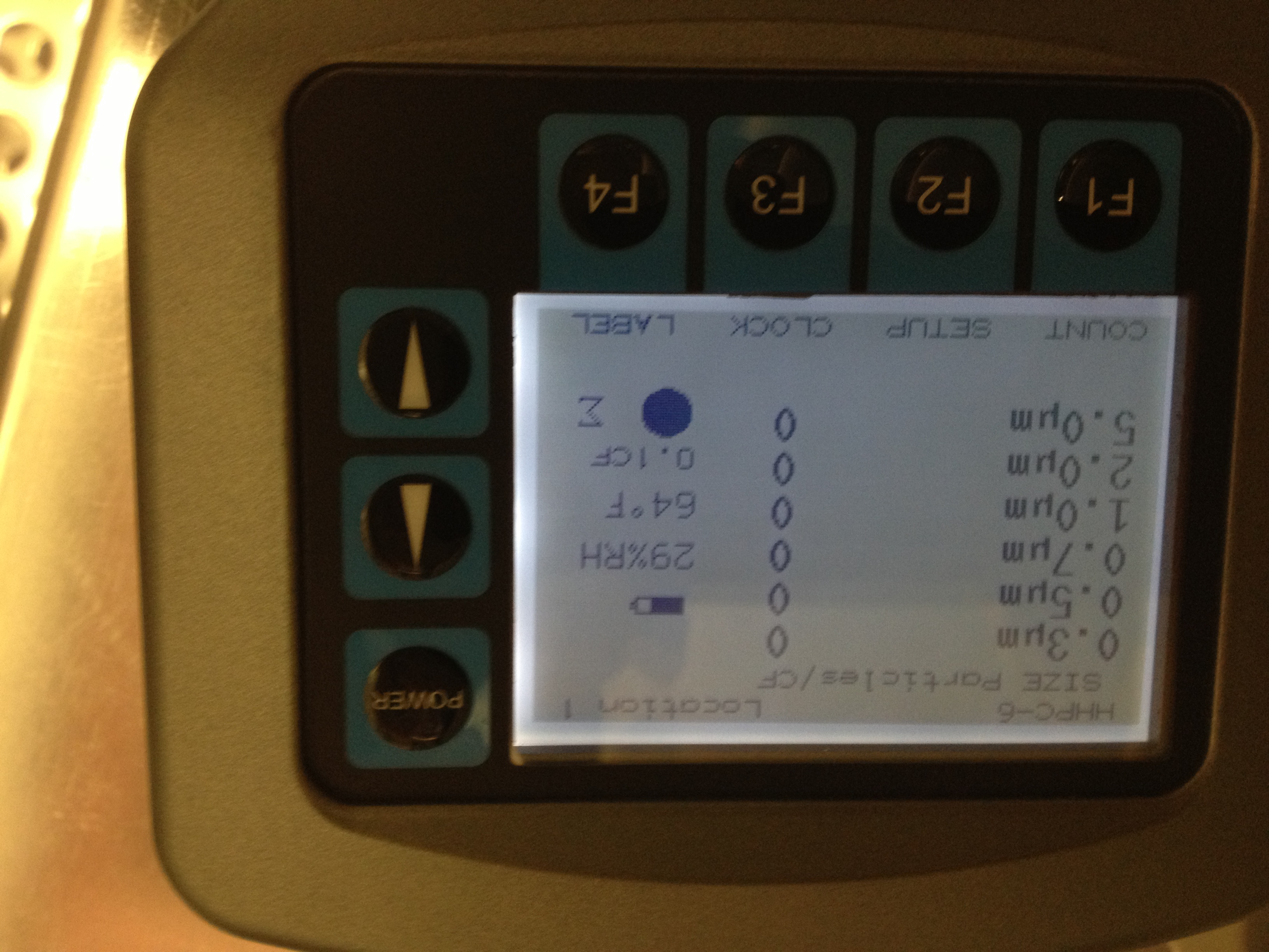
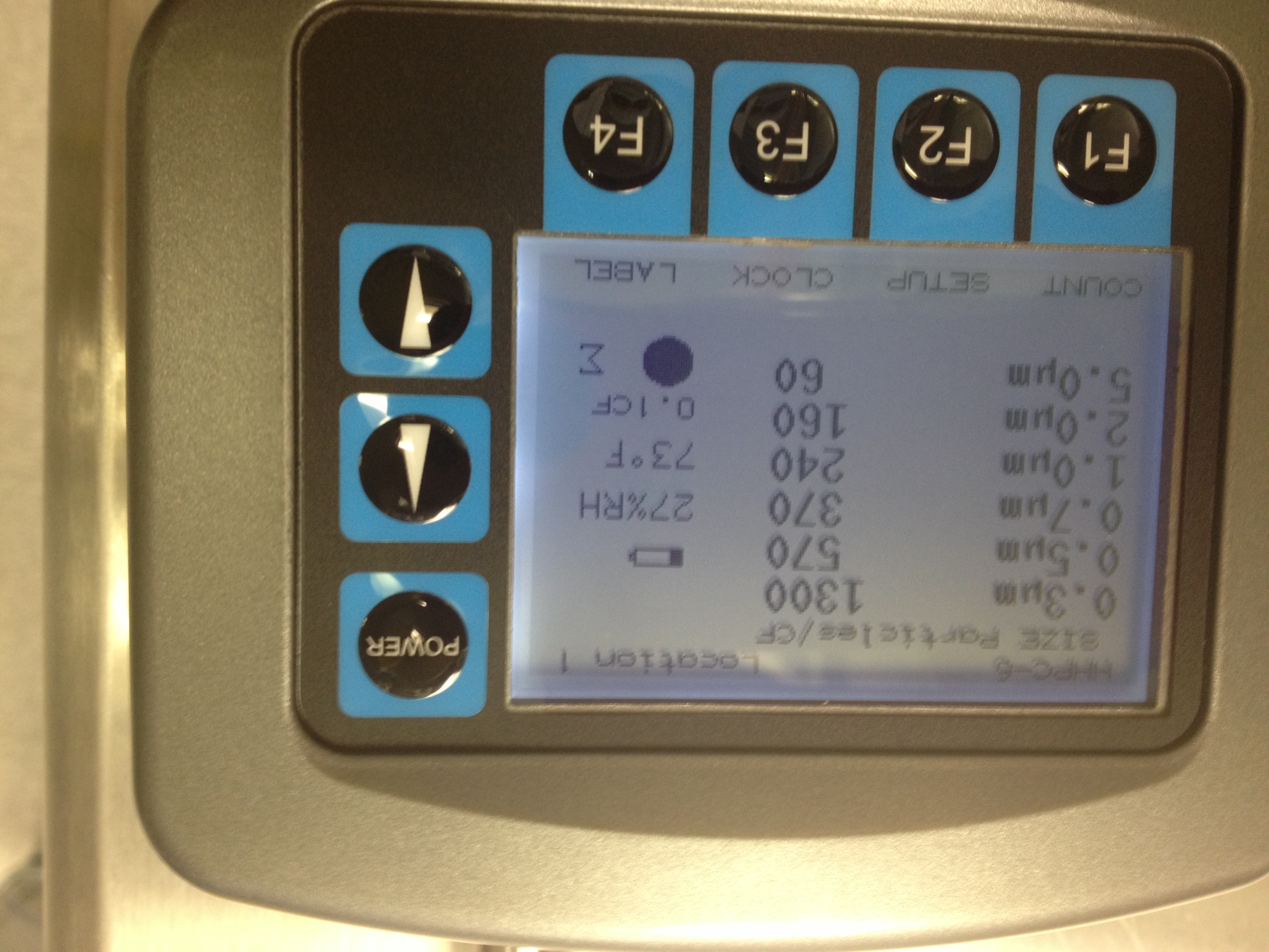
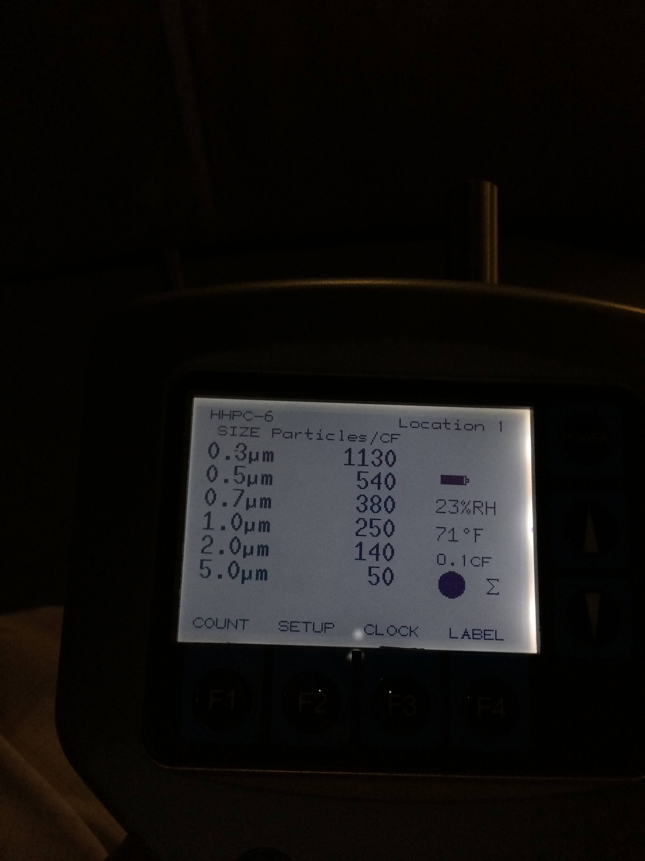
3.17pm particle counts (see pic 12)
0.3um...1300 counts
0.5um....570 counts
0.7um...370 counts
1.0um..240 counts
2.0um...160 counts
5.0um...60 counts
3.30pm..calling it quits