I and Dan replaced the bad UL BOSEM unit (SN of bobbin part of that assy is SN250, D0601106-C) with a good one (SN282) pulled out of spare "half-assembled" tip-tilt assy (base plate SN 034).
We also replaced UR one (SN258) with a spare (SN134) that was pulled out of the same half-assembled TT assy simply because we were not sure if the open voltage of SN258 (about 20000 counts) was too small. Later it turns out that 20k counts open voltage is not abnormal.
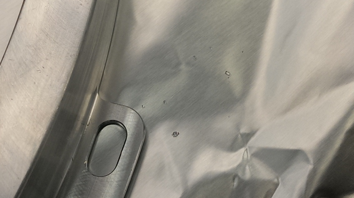
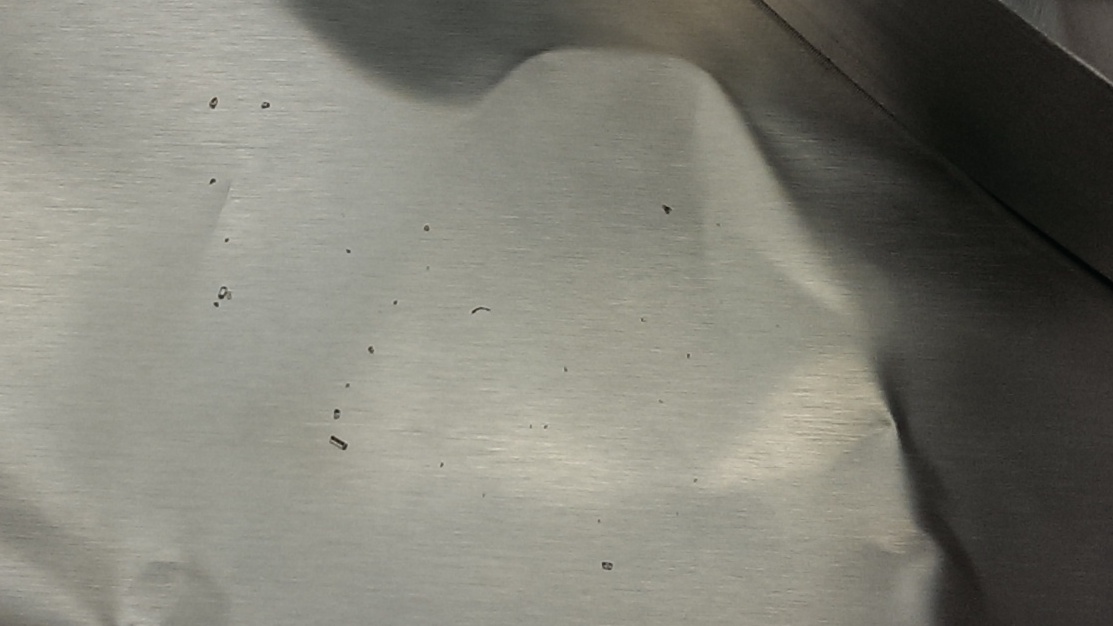
The newly installed units were of course assembled in the past but without fit check, and it turns out that the gap around the connector was non-existent and I had to loosen some screws and shift things around to make a good gap. I also used aluminum foil shim trick.
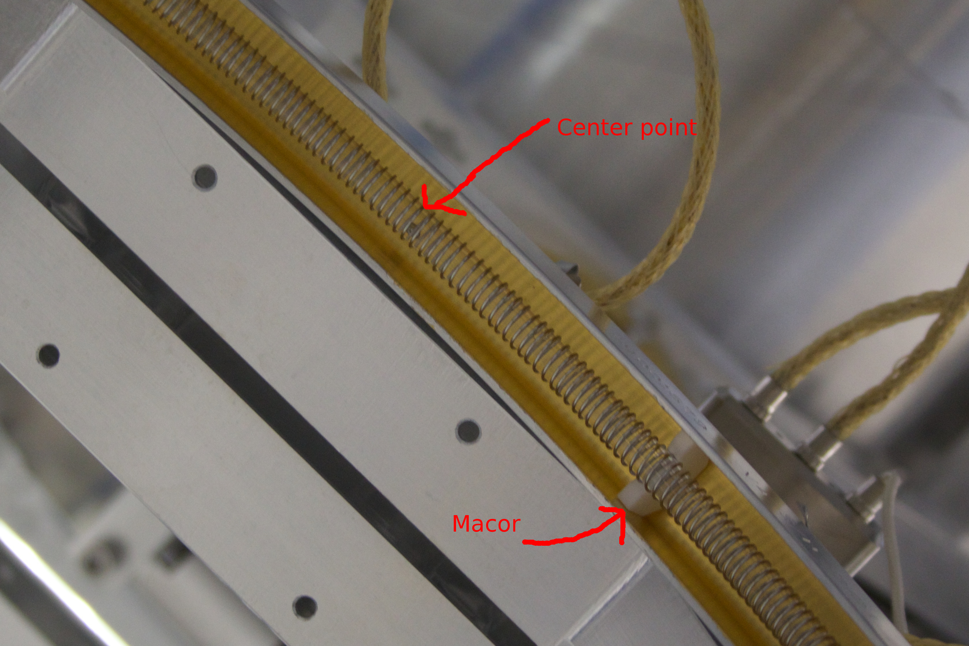
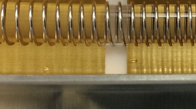
After this, we centered BOSEMs for all Tip-tilts to half the open voltage.
|
|
UL |
LL |
UR |
LR |
|
OM1 |
-16k |
-12k |
-16k |
-13k |
|
OM2 |
-11k |
-11.5k |
-15.5k |
-16k |
|
OM3 |
-16k |
-14k |
-16k |
-11.5k |
WFS DC, AS_C QPD, OMCR QPDs, OMC QPDs and OMC DCPDs all responded to flash light.
Beam diverters moved back and forth.
Picomotors moved. On cable #234, the first, the second and the third channels correspond to WFSA, WFSB and AS_C picomotors. On cable #235, the first channel is the downstream 2" mirror for the QPD sled, the second the upstream 1" steering.
Checked ground loops from outside the chamber, and all cables including SUS were good except beam diverters (we know that they ground inside the chamber) and OMC QPDs (shield grounted to the DCPD signal ground) and OMC PZTs (same as OMC QPDs).