J. Kissel, D. Barker, J. Batch, A. Pele
Another harrowing day of front-end code changes.
In summary, I've now completed and committed all the simulink / front-end model, MEDM screen, and macro file modifications for the HLTS, HSTS, and OMCS. This involved several more recompiles, reinstalls, restarts, and restores of all 10 models involved, a couple of more crashes and restarts of the DAQ, and a whole lot of eye-crossing details. The final modification -- to the OMCS front-end code -- has crashed the h1sush56 front end again (as the rest of these installs have, save h1sush2a for some reason), and almost undoubtedly because of the usual mx_stream failure. Thankfully, if did not crash the rest of the DAQ, so data taking should still hold over night.
Though I'm confident every thing I've done is legit, we should give a day to get things back up and running before we officially release everything to LLO. (Though I know they're not interested in more changes until they vent next Wednesday.)
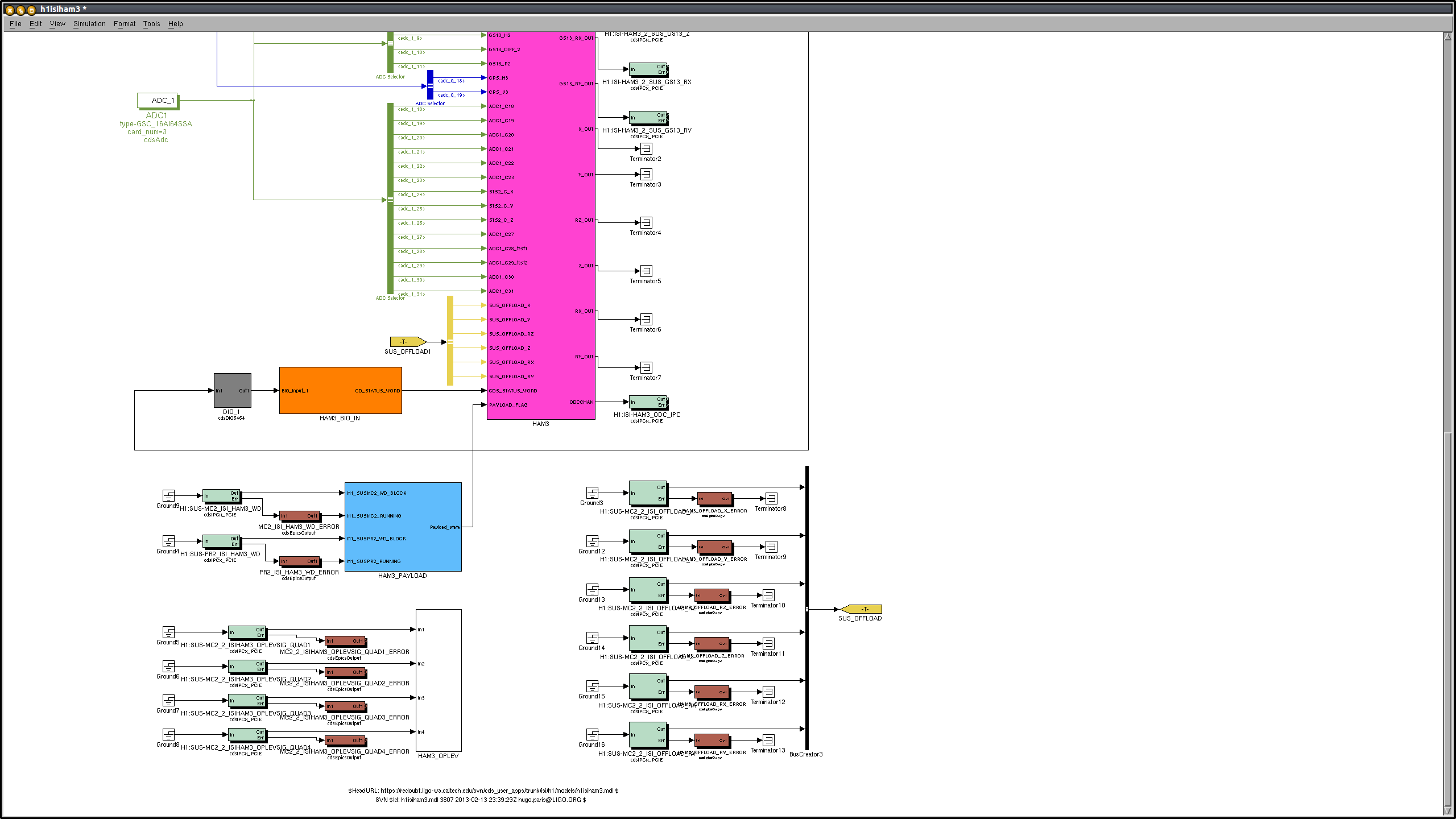
Of note -- It was not until I got to the MC_MASTER parts today, and getting some feedback from ISC folks that I realized -- for calibrated, interferometric control channel purposes (think IMC_X, PRCL, SRCL, MICH, DARM) -- we need to send out the output of each LOCK filter bank (including the top stage) to the top level to be sent over IPC to the OAF / Calibration model. For those SUS that aren't involved in global control, we'll just terminate the unused connections at the *top-level* of each model (currently only h1susmc2 is *actually* using this type of spigot to form IMC_X, the remaining IFO DOFs' control signals are pulled out for calibration in the LSC model). There are a couple of ways to do the calibrated channel thing; I'll bring up with ISC / Systems as to how we want to do it (because it's currently inconsistent across the ISC / IO models). Unfortunately, this means I've gotta go back to the QUADs and BSFM, but I'll wait for the discussion to conclude before I do so.
Next on the chopping block -- tackle the severe upgrades and merging needed on the HAUX / HTTS models. Then that finally, finally, OMG finally, will close out this gosh darn ECR. Then we can do it all over again with the watchdog modifications. #facepalm.