hugo.paris@LIGO.ORG - posted 17:22, Thursday 13 June 2013 (6750)
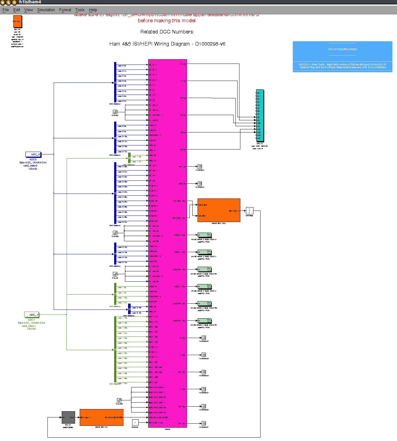
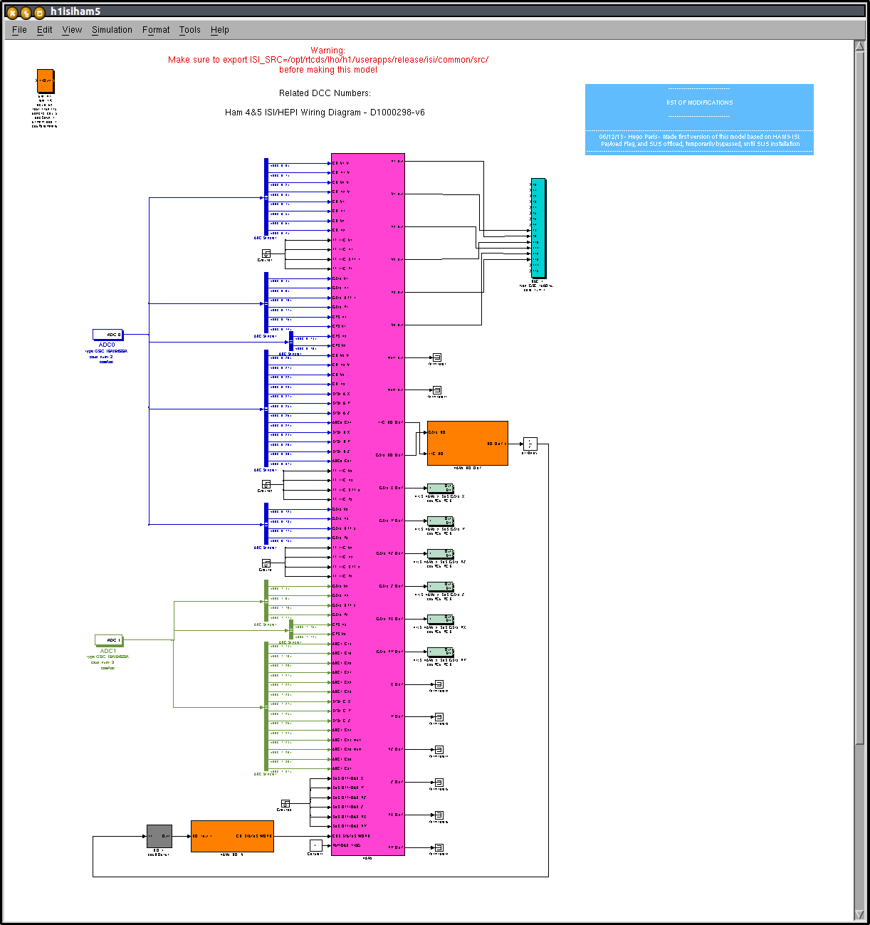
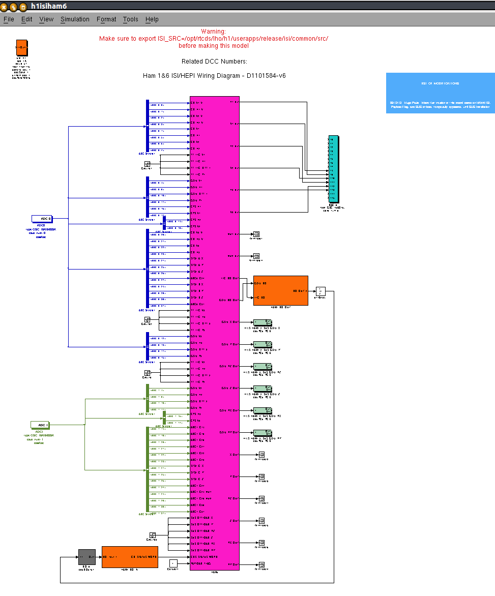
ISI models created: HAM4, HAM5, HAM6
Made the simulink models for the ISIs of HAM4, HAM5 and HAM6
- Payload watchdogs are bypassed (until the installation of Suspensions)
- SUS offload path is bypassed (until the installation of Suspensions)
Macro substitution text files created for those ISIs.
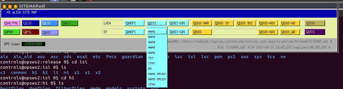
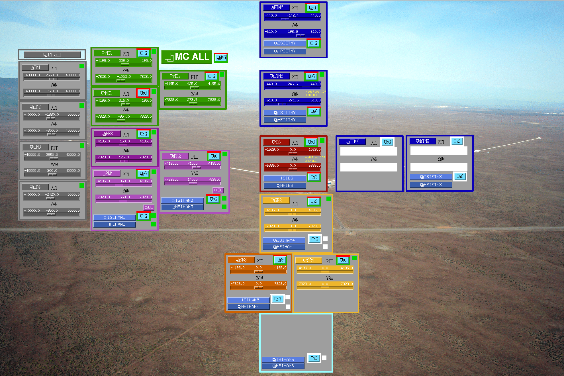
Added the related entries to the Sitemap.
Same work to come for the HEPIs of HAM4, HAM5 and HAM6.
Each new model will be restarted tomorrow. A DAQ restart will follow.
Models, sitemap, and mactosubstitutions were commited under the SVN:
- h1isiham4.mdl - r4717 initial, r4723 typo fix
- h1isiham5.mdl - r4718
- h1isiham6.mdl - r4722
- SITEMAP.adl - r4724
isiham5_overview_macro - r4721 simulink models for the ISIs of HAM4, HAM5 and HAM6
- Payload watchdogs bypassed (until the installation of Suspensions)
- SUS offload bypassed (until the installation of Suspensions)
Added the related entries in the correct ISI scroll down menu of the Sitemap.
Macro substitution text files created for those ISIs.
Mopdels were compiled and started.
Same work to come for the HEPIs of HAM4, HAM5 and HAM6. DAQ restart will follow.
Models, sitemap, and mactosubstitutions were commited under the SVN:
h1isiham4.mdl - r4717 initial, r4723 typo fix
h1isiham5.mdl - r4718
h1isiham6.mdl - r4722
SITEMAP.adl - r4724
isiham4_overview_macro - r4720
isiham5_overview_macro - r4721
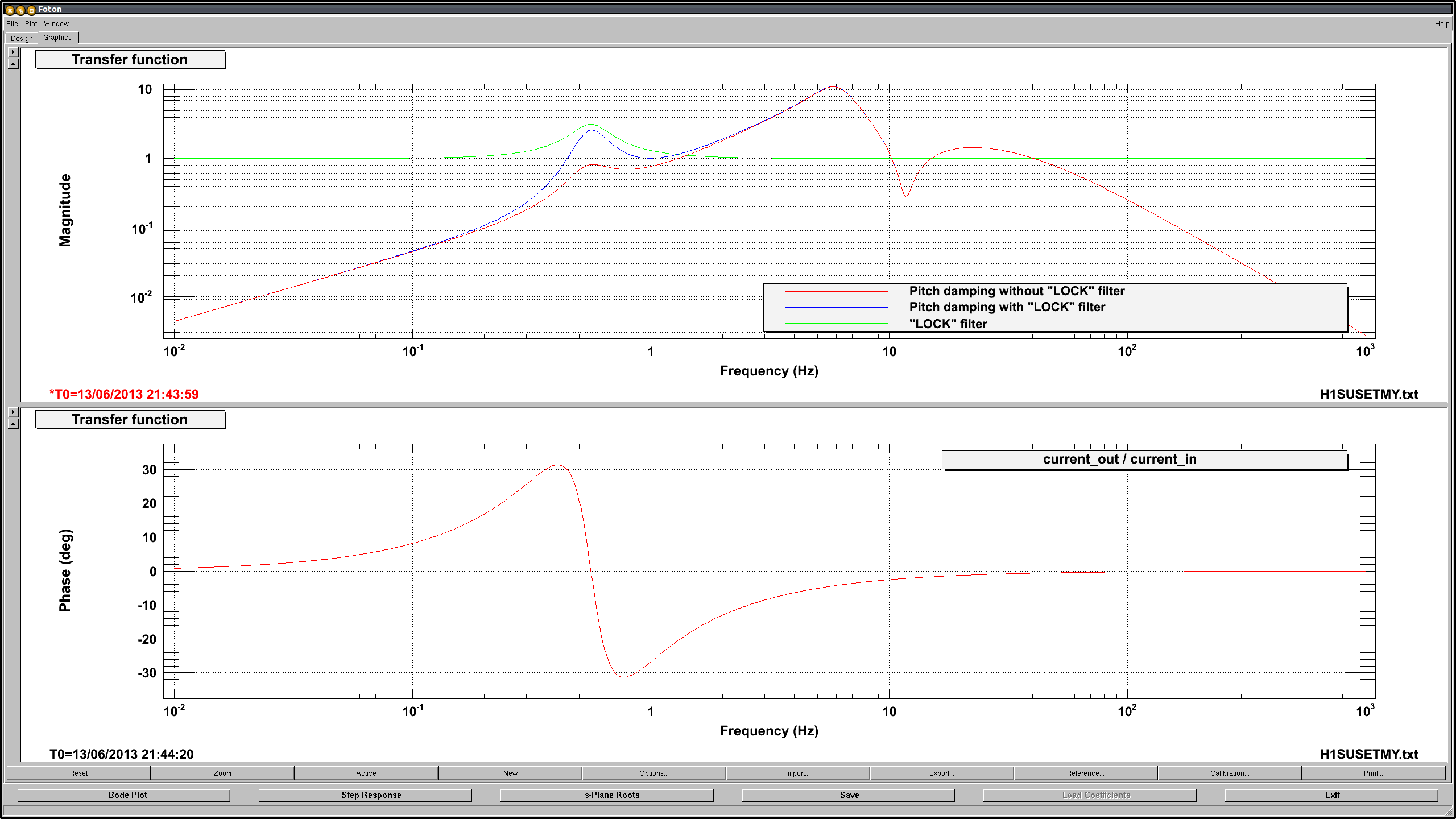
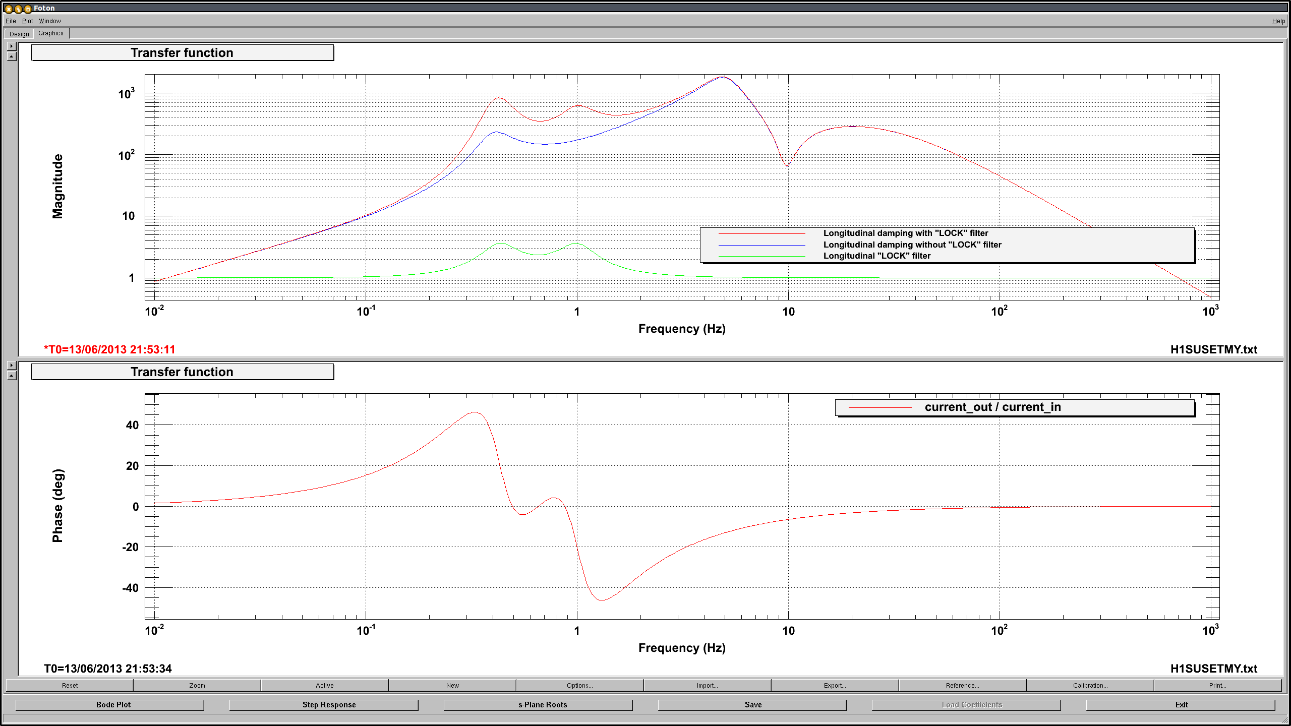
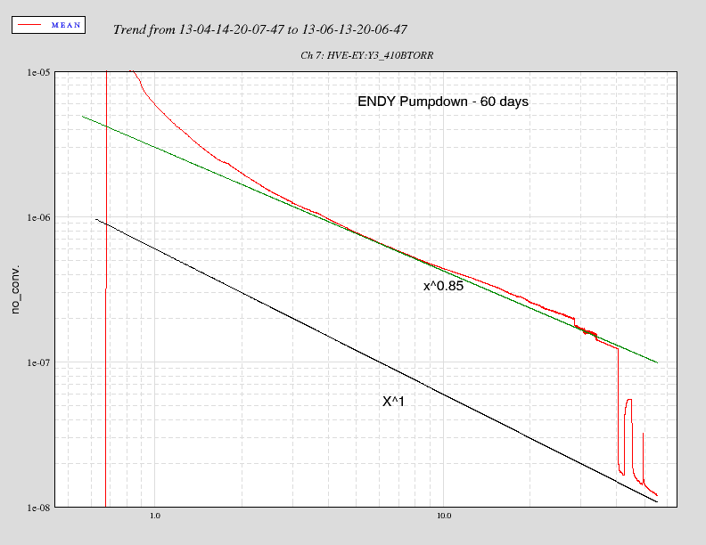
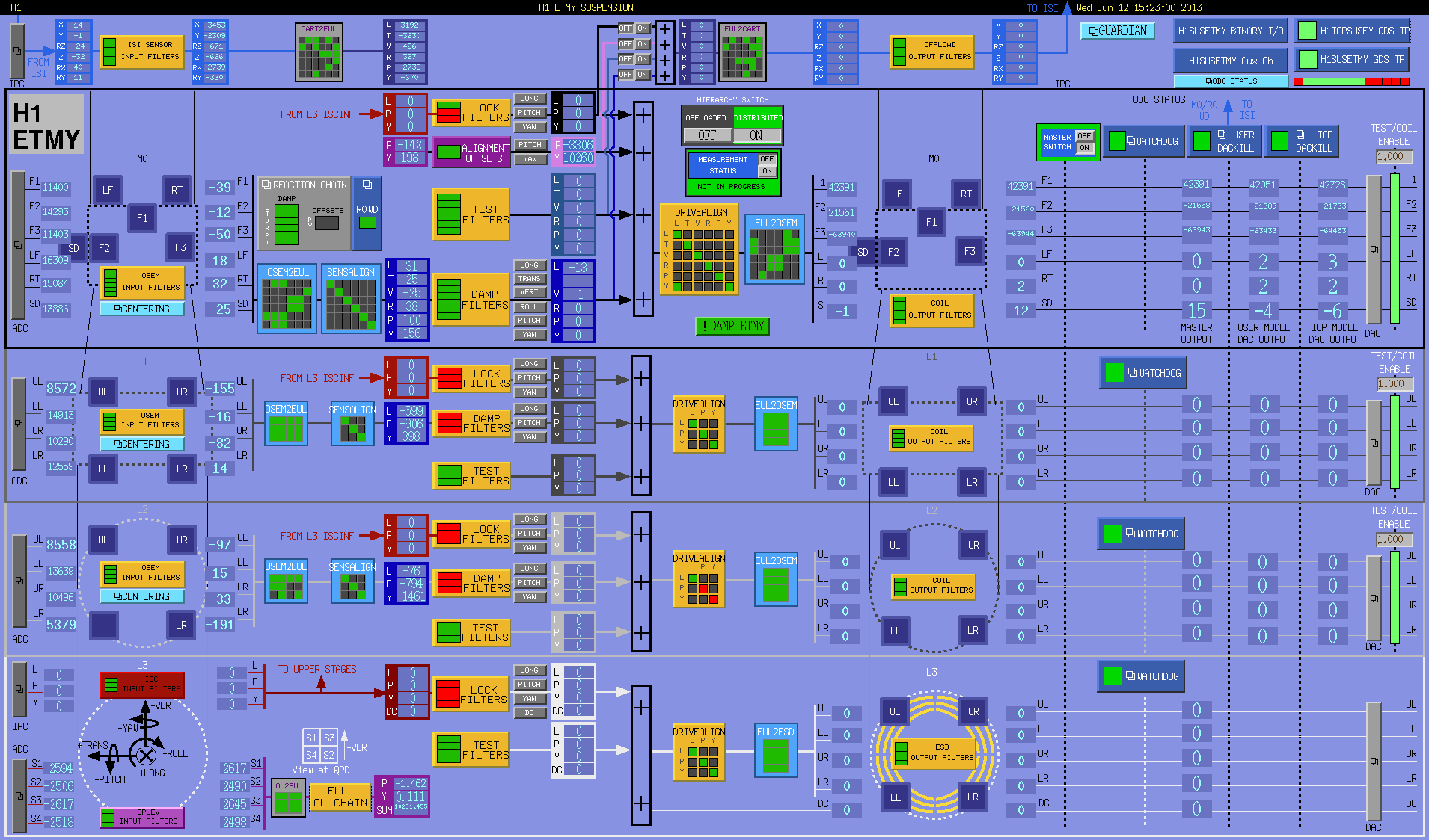
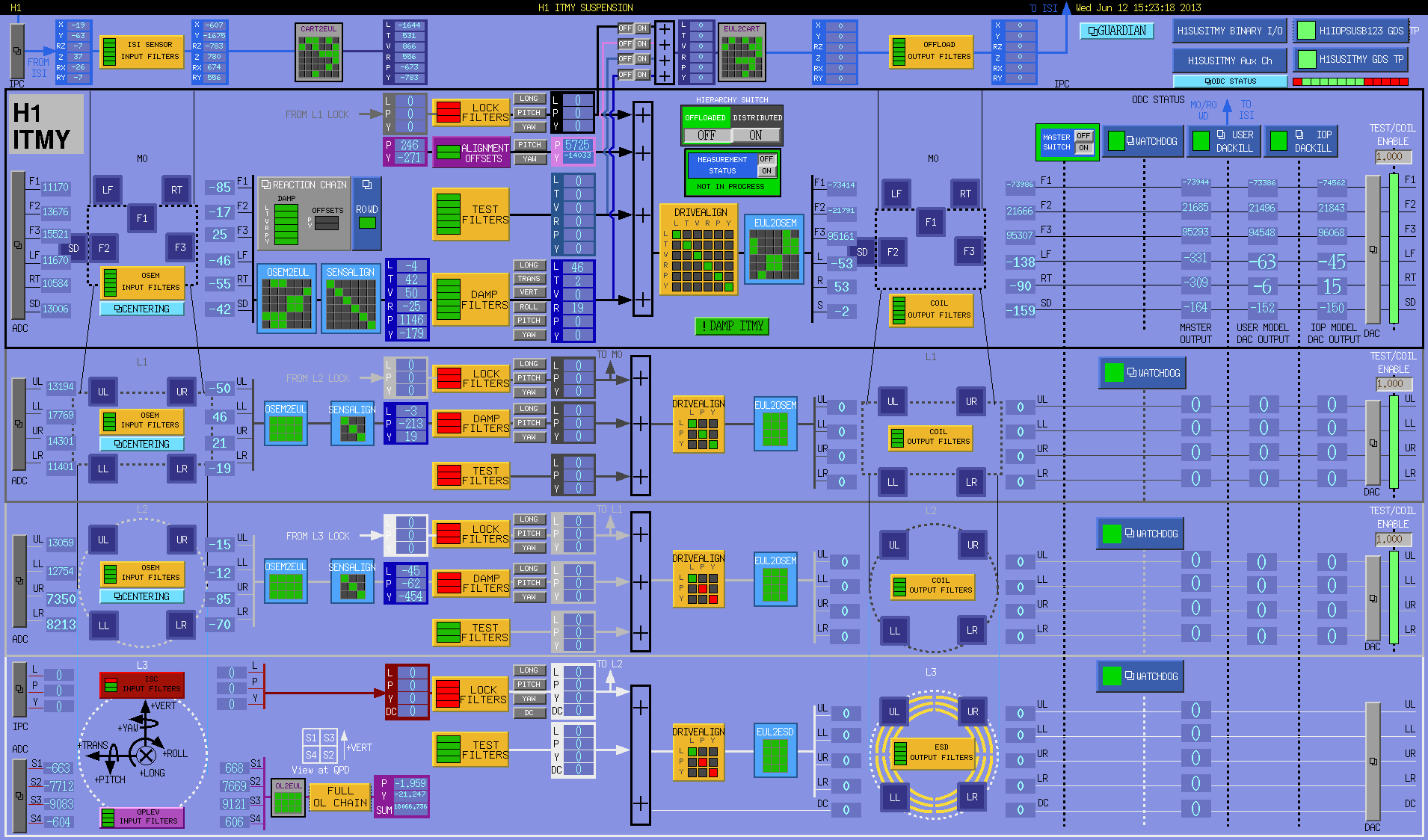
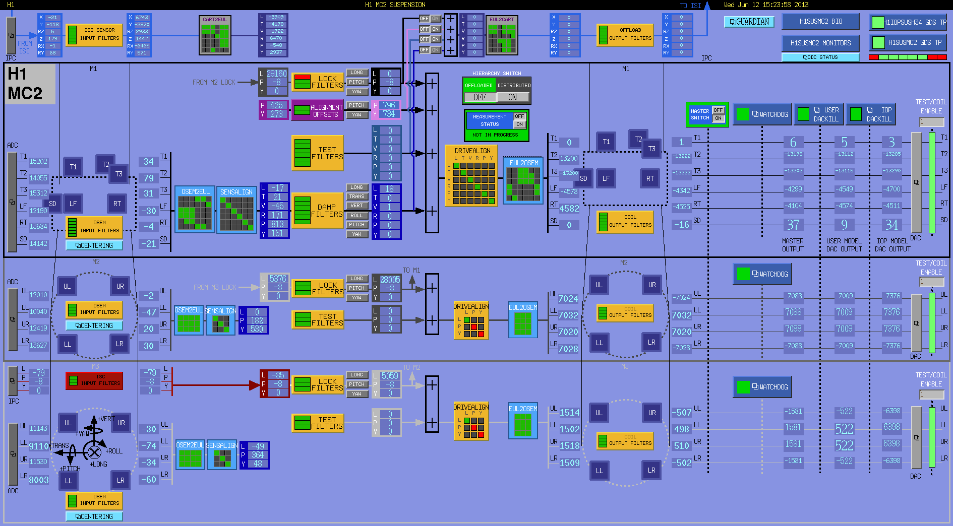
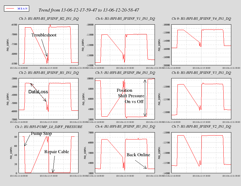
Images attached to this report