corey.gray@LIGO.ORG - posted 16:39, Tuesday 06 August 2024 (79466)
Tues DAY Ops Summary
TITLE: 08/06 Day Shift: 1430-2330 UTC (0730-1630 PST), all times posted in UTC
STATE of H1: Corrective Maintenance
INCOMING OPERATOR: n/a
SHIFT SUMMARY:
Big DARPA tour, Relay Tube was installed, and other prep work for pumping down, and then Les Guthman did some filming work.
LOG:
- 1445 Prep for morning tours (karen, kim, nelly, richard, tony,...)
- 1512-1518 Turning on light in the H1 PSL room for the tour (rick)
- 1555 Escorting Eric to Squeezer station for tour (Sam & later spelled out by sheila)
- 1545 karen/kim/nelly out
- 1535-1640 Acme pest control escort (chris)
- 1545 3IFO checks in lvea (tyler)
- 1831-1851 3IFO checks at MX & MY (tyler)
- 1545 DARPA tours begin
- 1545-1628 installing shutter for PCal at EY--requiring quick laser hazard transition (Tony, Shingo)
- 1600 OFI TFs on HAM5 (jeff)
- 1619-1704 Filter Cavity End Station cleaning (kim, karen, nelly)
- 1704-1801 EX cleaning (kim)
- 1704 MY cleaning---they skipped EY cleaning due to swarming wasps at the EY outhouse (karen, nelly)
- 1632 Relay Tube install/pump prep (travis)
- 1645 Janos joined (gerardo also went out there at some point)
- 1729 Meeting with VAC group about test of receptacles (richard)
- 1737 Janos grabbing items at EX
- 1756-1940 LN2 truck at MX CP6
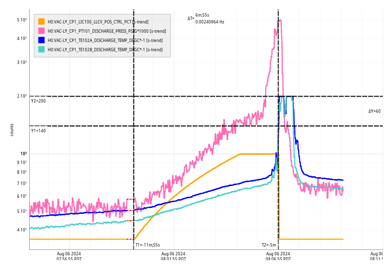
- CP1 (LVEA y-beam manifold, (but didn't catch arrival))
- CP1 top-off caused aa VAC SDF overfill diff (it should return to green after LN2 overfill stops.
- 1907-1920 lvea checks (betsy)
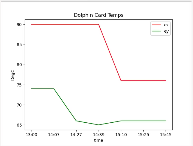
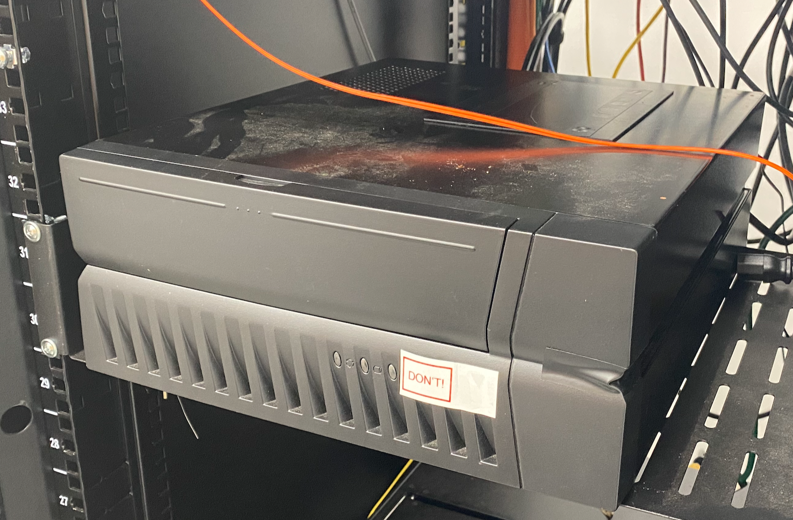
- 2003-2030 EX computer racks to check overheating dolphin computers. (marc, erik)
- 2055 Now visiting EY to put a plate on the computer chasis to cool it down (dave, erik)
- 2145-2211 Visiting EX to put a plate on the computer chasis to cool it down (dave, erik)
- 2014 EPO crew grabbed LEGO ifo from ops station.
- 2011 Pcal measurements (dripta, cervane, tony joining later)
- 2326-2333 Heading back into the lab
- 2028 FAMIS checks in LVEA & then moved on to arms (chris)
- 2058 Les Guthman film crew scoping out Filter Cavity Tube Enclosure (Oli escorting)
- 2245-2330 interviewing Betsy in Control Room