Good first half of the shift. The IFO has been locked for the past 15.75 hours,and continuously Observing for 9 hours. Winds are light and the microseism has been declining over the past 2 hours. There were several mid-sized (mag4.5 to 5.5) earthquakes in and around the Pacific that rung up the microseism. They were not powerful enough to cause any difficulties.
TITLE: 04/25 Eve Shift: 23:00-07:00 UTC (16:00-00:00 PST), all times posted in UTC
STATE of H1: Observing at 113Mpc
INCOMING OPERATOR: Jeff
SHIFT SUMMARY:
Other than two separate events knocking us out of OBSERVING, it has been a nice shift. And seismically it is really calm & quiet. (but I said that last night, too!)
LOG:
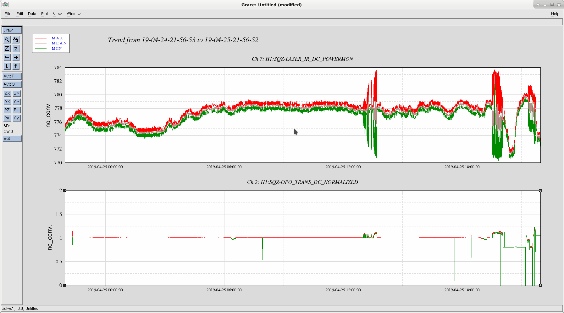
1:37:23: Bumped to COMMISSIONING due to SQZ/OPO unlocked! (this happened while I was out of the Control Room!)
1:38:39: Looks like the SQZ Manager took care of everything and returned SQZ_MANAGER to the Nominal SQUEEZING state on its own. But when I returned I did not notice H1 was out of OBSERVING! (If I was a good operator I should have first checked VERBAL for anything while I was out, and then should have seent we were out by looking at some of our wall monitors.)
2:11 Back to OBSERVING! (It was a this time I noticed we were out of Observing because I was Reloading the GWI.stat medm webpage on nuc1 (luckily it dies frequently, and it raised my attention!)
Text of SQZ_MANAGER node log is attached as a pdf.
Summary: Always check your H1 after stepping out of the Control Room!! Don't be like me and keep us out of OBSERVING for ~30min!! :-/
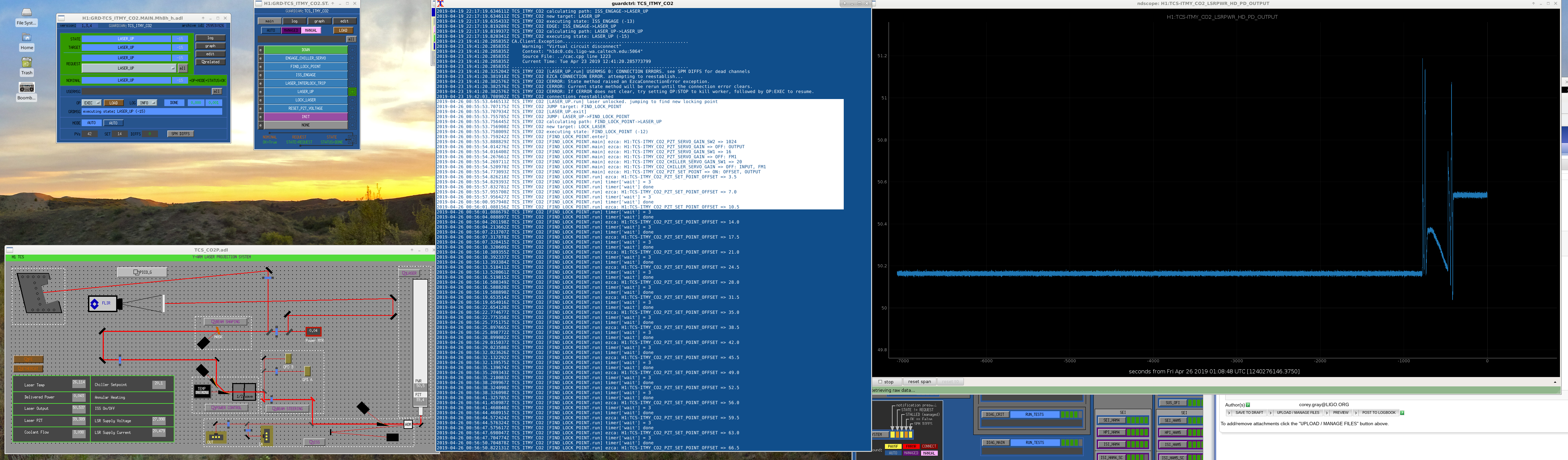
0:55 H1 Bumped OUT of Observing.
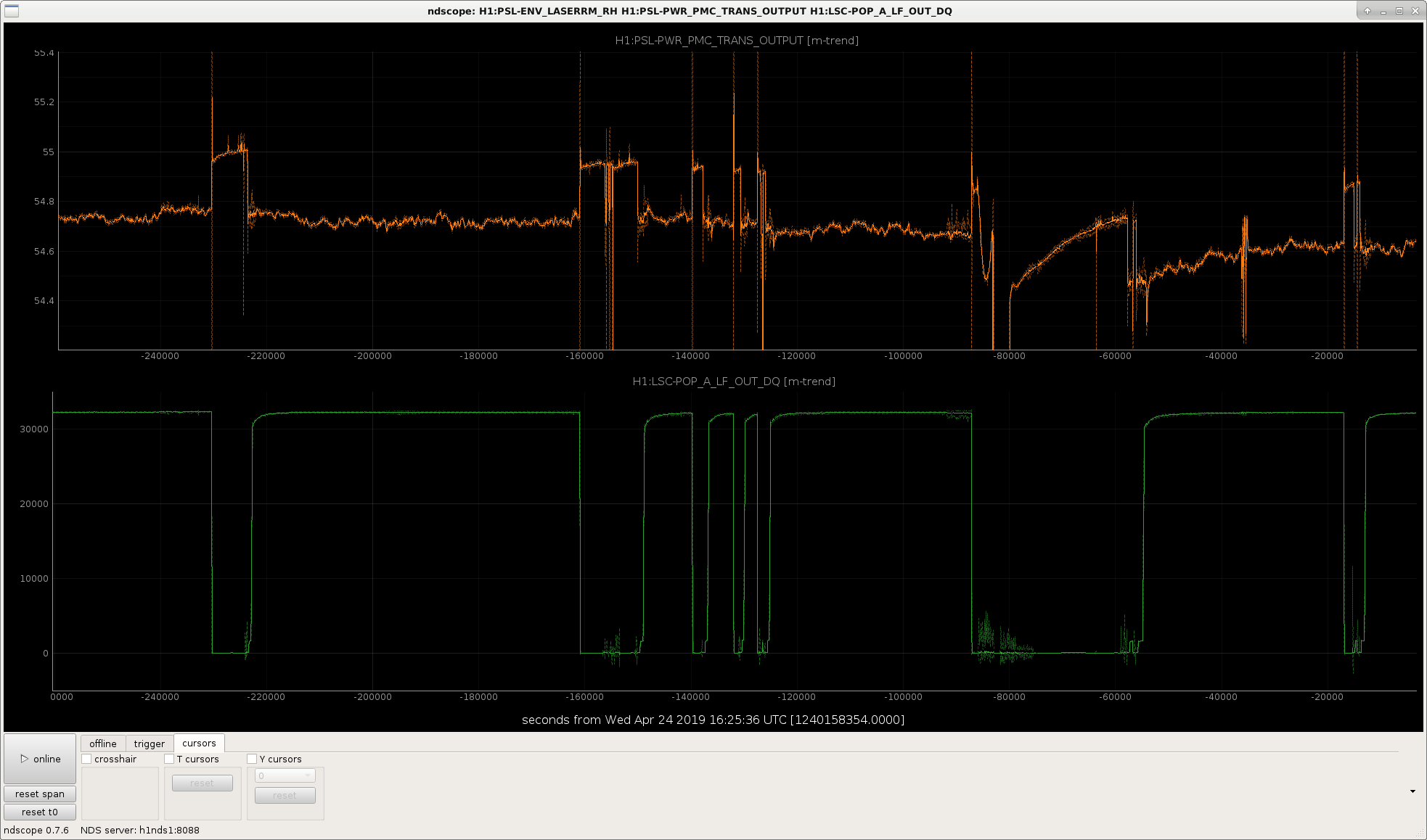
This was found to be due to an "unlocked TCS_ITMy_CO2 laser". Looking at NDScope (see attached screenshot), the laser power took a jump up from ~50.16W and the TCS_ITMY_CO2 guardian node spent a few minutes at the FIND_LOCK_POINT adjusting an offset (see attached pdf of log file). Eventually the guardian returned to its nominal state, of LASER_UP (at 1:01utc). It had a "new pzt setpoint of 50.536W".
At this point, it looked like everything was good to go to Observing, so at 1:06utc, I returned H1 to Observing.
Summary: TCS ITMy CO2 laser was unlocked for a few minutes & Guardian restored laser. However, laser power changed from 50.16W to 50.536W. I have not seen this before.
This is normal. When the CO2 laser goes to reacquire lock, it will scan with its PZT to find a point where it has good buildup. This point changes from lock to lock due to a variety of reasons, so it's possible to have slightly different powers from the laser itself. [[abs(50.16 - 50.54)/50.16 = 0.76% change]]
Not too big of a deal since we control the power down stream anyway.
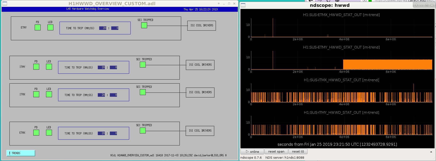
I've added a TRENDS button to the lower left of the HWWD MEDM screen. This allows you to trend the HWWD channels for 1, 2 and 3 months in the past.
How to read the trends: a value of 2 means the photodiode RMS exceeded its threshold, this is most probably due to physical movement of the test mass. A value of 8 means the LED draw current fell below threshold, this most probably means the suspension was under high drive and its monitor voltage dropped.
ITMX, ITMY show val=8 at a medium rate. ETMY shows val=8 at a high rate (starting about 6 weeks ago). ETMX is quiet, just showing few val=2 over two months ago.
Lines which go off the top of the y-axis are most probably bogus DAQ values and should be ignored.
Patrick Thomas, Sheila
This morning on the detchar call, we discussed switching the glitch monitor that is displayed in the control room from DMT-Omega to omicron, since there are differences in the glitches which show up in the two tools and it seems that people have more confidence in the omicron glitches being real (or having a real impact on the searches) right now.
The url for the omicron monitor is:
https://ldas-jobs.ligo-wa.caltech.edu/~detchar/monitor/omicron/
We have displayed this on the bottom half of nuc0 and Patrick is updating the operator instructions (FOM) wiki.
We took about 4 hours of time for commissioning today:
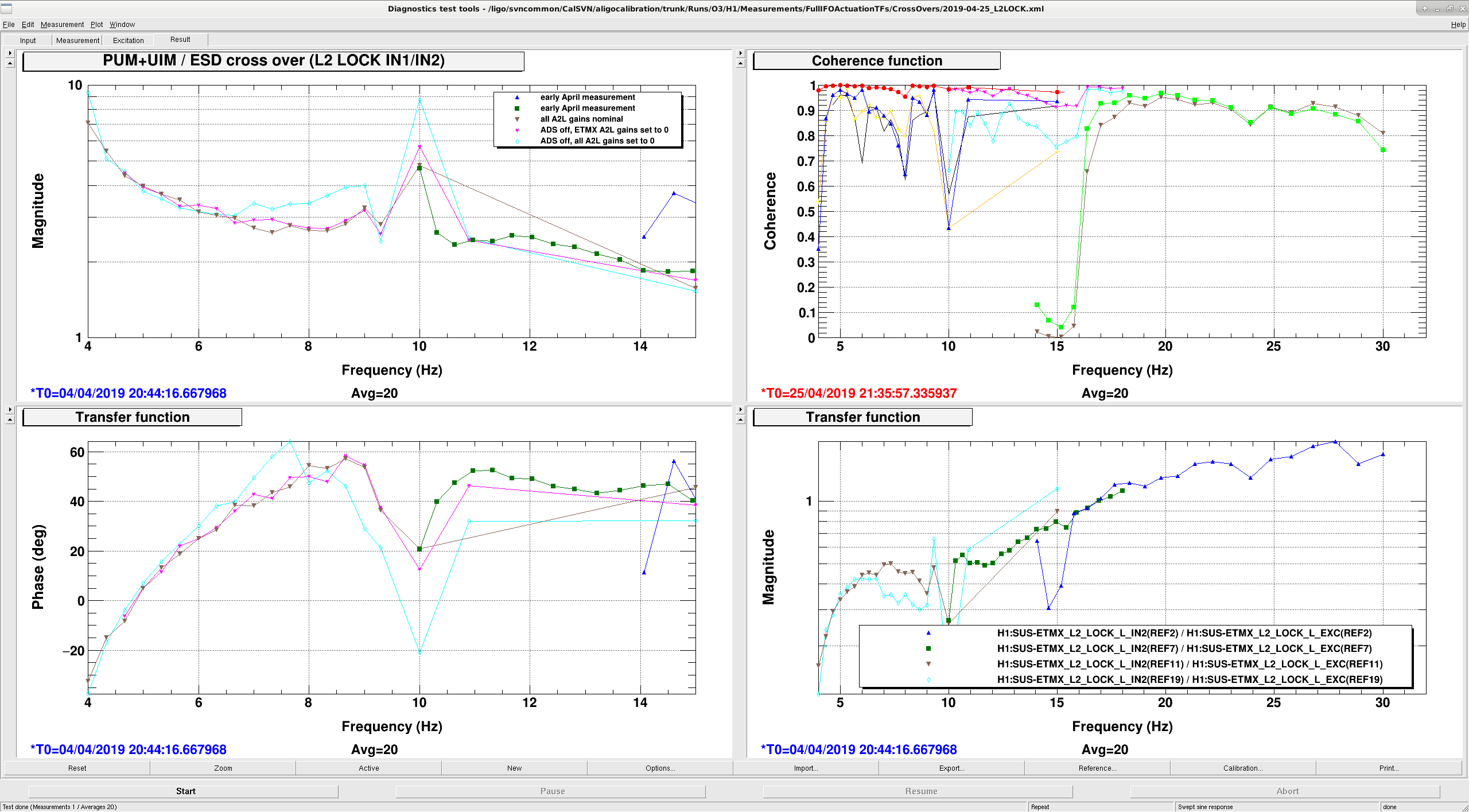
A quick summary of the cross over measurements (Jenne, Sheila):
Motivation:
Measurement:
Here are the measurements from this time plotted against a pyDARM model.
The blue line is a model of what the L2 LOCK IN1/IN2 measurement is expected to look like based on the pyDARM model of the actuators. The green dots are measurements of this crossover made on April 3rd, they are plotted here just so that you can see some higher frequency data (we didn't retake any higher frequency measurements)
These measurements could be explained by a coupling of the length drive to either the angle of the optic through a mechanical coupling or to the angular sensor, the ASC loop then tries to actuate in response, but there is a coupling from angle back to length because we are not doing a nice job of a frequency dependent angle to length decoupling. When we turned off the A2L decoupling, by setting the scalar gains to 0 but not running the ADS so that the spot positions stayed in their normal positions. In principle, a more accurate frequency dependent A2L decoupling could be used to reduce this effect.
In 47824 and 47982 we saw that when we turned off the L2A decoupling filters, which increased the gain of the PUM by getting rid of the L2A2L coupling that comes from having our spots well off center and not routing the L2A output through the A2L decoupling, we had a crossover instability around 8 Hz. This was solved by turning off the 4.5Hz boost in the PUM lock filter, which doesn't make complete sense but it is plausible given these emasurements that the problem with the boost was caused by these angular cross couplings, especially if there are features that are not resolved in this measurement.
TITLE: 04/25 Eve Shift: 23:00-07:00 UTC (16:00-00:00 PST), all times posted in UTC
STATE of H1: Observing at 111Mpc
OUTGOING OPERATOR: Cheryl
CURRENT ENVIRONMENT:
Wind: 5mph Gusts, 3mph 5min avg
Primary useism: 0.02 μm/s
Secondary useism: 0.10 μm/s
microseism is lower than yesterday and noticeably under the 50th percentile (Yay!), and winds are generally calm (under 10mph).
QUICK SUMMARY:
H1 was in OBSERVING when I arrived (and has been for 50+min).
I've edited the guardian to use the sum of REFL A and REFL B 9I for CARM control, which should give us sqrt(2) lower frequency noise at low frequencies (below 1kHz) where the frequency noise is limited REFL shot noise.
To summarize the story of these two sensors, in case Detchar is interested in looking at these:
We've had this REFL B channel available since it was installed in November and phased in early December. Since then REFL B has been an out of loop sensor for frequency noise, since Refl A has been the only one used in the loop. The Refl A readback was calibrated into volts on April 16th, so that REFL A +refl B have the same units.
This tuesday (April 23rd) I switched the CARM loop from using REFL A to REFL B, as a temporary test because the better whitening on the REFL A readback means that it has better ADC noise clearance to use as a out of loop sensor. This was only temporary, and we continued to use only REFL A in the CARM loop since then.
Craig and Georgia also increased the gain of the CARM loop by 3dB on Tuesday which helps to suppress the frequency noise (due to IMC shot noise) above 1 kHz. Since then, it has been noted (Ed's shift summary) that there was extra high frequency noise at the beginning of the lock that went away a few minutes into the lock. It may be that the optical gain of REFL 9 is higher in the first few minutes of the lock, and that the CARM loop has some gain peaking with the higher gain.
In this lock, starting at about 19 UTC April 25th, we saw this happening again. Jenne and I turned down the CARM gain by a few dB, and saw that this also had an impact on the power build ups. A few minutes later, the higher gain (12dB on IN1 gain) was fine.
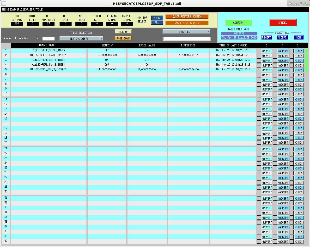
This is the list of SDFs that I accepted in the observe snapshot to capture these changes.
Spectra of REFL A and B for the two different configurations: 48773.
TITLE: 04/25 Day Shift: 15:00-23:00 UTC (08:00-16:00 PST), all times posted in UTC
STATE of H1: Lock Acquisition
INCOMING OPERATOR: Patrick is covering OPS 3PM-4PM local (22:00-23:00 UTC) then Corey
SHIFT SUMMARY: H1 is in NLN, commissioning
LOG:
Currently On Site / at MX/MY / in LVEA / taking measurements:
22:26 UTC Observing
Today the intensity servo has been railing negative. It seems like it's trying to get more power through the coupler in order to meet the set point which normally would set the OPO input to the coupler to 20mW.
The changes I made today to try to mitigate the issue:
Adjusted SHG crystal temperature to optimize the conversion efficiency, this is to get more green out. Although we were already getting 40mW. Though I don't think that was the issue.
Adjusted half waveplate to get more power through when the servo is off so the default power sits around 18mW into the coupler.
SHG_PWR_TRANS_OFFSET went from -325 to -342
AOM low limit changed to -9000 this corresponds to nealy 20mW into the coupler.
I think the pump laser drifting is the problem here. When the red output goes down, green output goes down and the servo keep asking for more power until it hits the limit. The laser is still acting up as I'm writing this alog. I think it's going to keep hitting the rail.
The notification of ALS fiber polarization percentage is still super annoying. I just changed DIAG_MAIN to only report on the ALS fiber polarization when we're acquiring lock. It will not put up a message when we're in NomLowNoise anymore.
Last night, due to some guardian fast EZCA connection errors (alog 48744 and comment), Georgia and Corey had to manually turn on the BS pitch offloading. Since Ed was unable to load the new version of the guardian that has the fast EZCA parts removed (alog 48747), he ran the old code and seems to have gotten a very similar error. It looks like he accepted the SDF diffs (alog 48753), including the fact that BS offloading of pitch to the top mass is off. So, at least for the entirety of this lock so far, we've been running without any pit offloading for the BS top mass. Things seem okay for now (current lock is 7.75 hours and going), so I'm not going to turn it on just yet.
I believe that I have found and fixed the errors in the non-fez version of ISC_GEN_STATES.py, so I have put Georgia's modifications back in (with the fixes). We just lost lock (I don't know why, but I hadn't reloaded or changed anything in the running code), so I've reloaded the guardian and hopefully next lock we won't be plagued by this problem again.
We got through the acquisition sequence okay, and the BS pit top mass offloading is on as it should be, so I think we can call this one case closed.
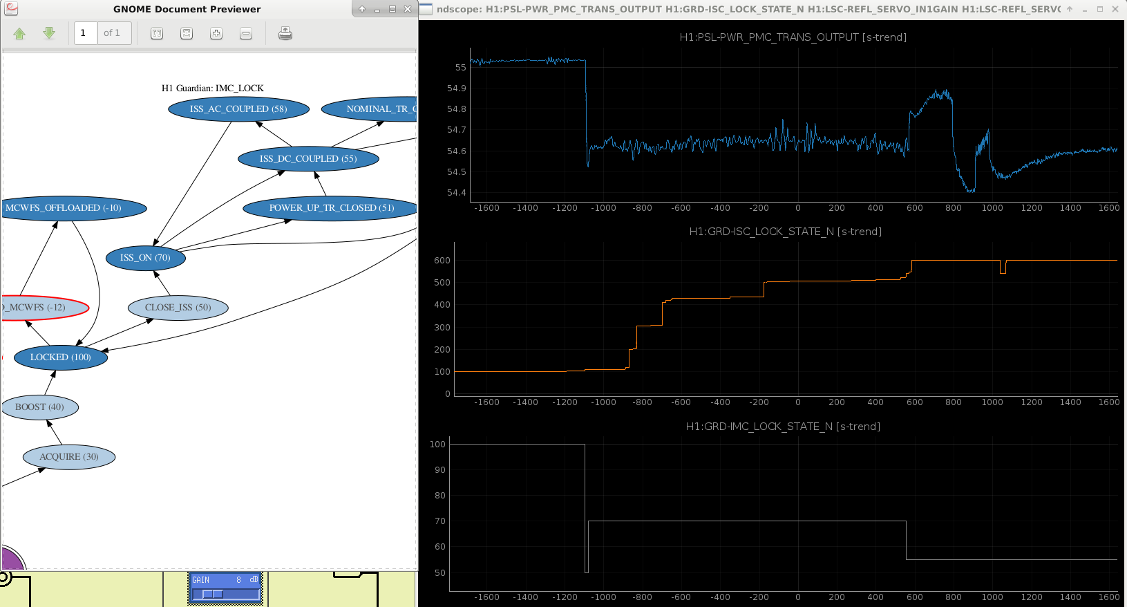
Matt H. at LLO noticed that their PMC transmission changes slightly with IFO lock state (alog here) and asked me if we see the same thing. Never having noticed this before, I took a look. Sure enough, we do, see attached; when the IFO is locked PMC transmission drops slightly. The change is slight (~0.3 W), so I don't think this is an issue, just noting it here so folks are aware.
I should note that we are using the new, all-bolted PMC while LLO is still using the original aLIGO PMC. Also, the movement in PMC transmission immediately followed by it's loss, return, and resulting ramp-up seen on the right half of the plot were caused by yesterday's PSL enclosure incursion and small water leak repair.
I had a closer look at exactly when the PMC transmission drops - as Adam noted at LLO, it occurs when we turn on the ISS second loop. The second loop is first engaged (with AC the coupling servo on) quite early in our lock acquisition sequence - in the DRMI_LOCK_CHECK_ASC state of the ISC_LOCK guardian, this causes the first step in PMC power in the attached screenshot. We get a second kick when we DC couple the ISS second loop, at the end of the lock acquisition sequence.
Today I took some frequency noise measurements. Posted are the results and the file locations.
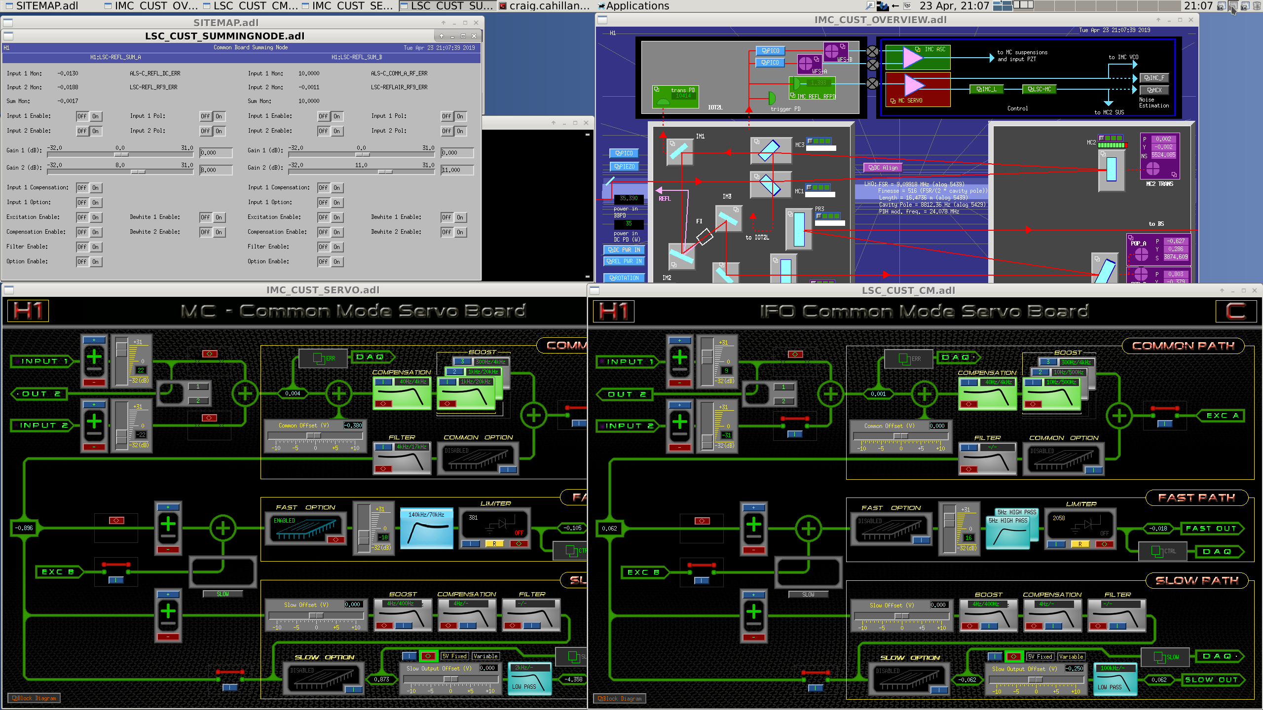
I increased CMB IN1 from +9dB to +12dB. We should always do this after thermalization of the IFO.
We can't increase the CARM digital gain too much or we'll hit the FSR with the CARM UGF. We have to wait for the optical gain to decay and replace it with digital gain.
POP18 NORM MON is at ~47 cts now, but is at around 60 when we first lock. We should wait until we hit around 50 cts, then up the CARM gain.
IMC Locked Alone at 35 W
- IMC REFL stitched spectra : /ligo/home/craig.cahillane/Git/IFO/IMC/data/Spectra/StitchedSpectrum_20190423_IMC_REFL_IMON_Spectra_IMCAlone_35WInput_IN1_22dB_SecondBoostOn.txt
- IMC OLG : /ligo/home/craig.cahillane/Git/IFO/IMC/data/TFs/20190423_IMC_OLG_IMCAlone_35WInput_IN1_22dB_SecondBoostOn.txt
- IMC MCL Crossover : /ligo/home/craig.cahillane/Git/IFO/FrequencyNoise/data/20190423_IMC_MCL_Crossover.xml
- MC2 to IMCF TF (Refs 16 and 17): /ligo/home/craig.cahillane/Git/IFO/FrequencyNoise/data/20190423_MC2_to_IMCF_35W.xml
Full Lock at 35 W
- REFL B Spectra : /ligo/home/craig.cahillane/Git/IFO/CARM/data/Spectra/StitchedSpectrum_20190423_REFL_B_35W_Input_CMBIN1Gain_9dB.txt
- REFL A Spectra : /ligo/home/craig.cahillane/Git/IFO/CARM/data/Spectra/StitchedSpectrum_20190423_REFL_A_35W_Input_CMBIN1Gain_9dB.txt
- CARM OUT2 Spectra : /ligo/home/craig.cahillane/Git/IFO/CARM/data/Spectra/StitchedSpectrum_20190423_CARM_OUT2_35W_Input_CMBIN1Gain_9dB.txt
- IMC REFL Spectra : /ligo/home/craig.cahillane/Git/IFO/CARM/data/Spectra/StitchedSpectrum_20190423_IMC_REFL_35W_Input_CMBIN1Gain_9dB.txt
- IMC TEST1 Spectra : /ligo/home/craig.cahillane/Git/IFO/CARM/data/Spectra/StitchedSpectrum_20190423_IMC_TEST1_35W_Input_CMBIN1Gain_9dB.txt
- CARM OLG w/ CMB IN1 = +9dB : /ligo/home/craig.cahillane/Git/IFO/CARM/data/TFs/20190423_213400_20190423_CARM_OLG_FullLock_35W_Input_60mV_Exc.txt
- CARM OLG w/ CMB IN1 = +12dB : /ligo/home/craig.cahillane/Git/IFO/CARM/data/TFs/20190423_214036_20190423_CARM_OLG_FullLock_35W_Input_60mV_Exc_12dB_CMBIN1Gain.txt
- IMC OLG w/ CMB IN1 = +9dB : /ligo/home/craig.cahillane/Git/IFO/IMC/data/TFs/20190423_212909_IMC_OLG_FullLock_35W_Input_0dBm_Exc.txt
- IMC OLG w/ CMB IN1 = +12dB : /ligo/home/craig.cahillane/Git/IFO/IMC/data/TFs/20190423_214142_IMC_OLG_FullLock_35W_Input_0dBm_Exc_12dB_CMBIN1Gain.txt
- LSC MCL Crossover : /ligo/home/craig.cahillane/Git/IFO/FrequencyNoise/data/20190423_LSC_MCL_Crossover.xml
- MC2 to REFL9 Cal TF (Current): /ligo/home/craig.cahillane/Git/IFO/FrequencyNoise/data/20190423_MC2_to_IMCF_35W.xml (This is the same as the MC2 to IMCF template above. The current references are in full lock, Refs 16 and 17 are from IMC locked alone.)
- Frequency Noise Injs +9dB: /ligo/home/controls/craig.cahillane/Git/IFO/FrequencyNoise/data/Injections/20190423/1240118413_GPSstart_FrequencyNoise_CMB_EXC_inj_2000_7000_Hz.pkl
/ligo/home/controls/craig.cahillane/Git/IFO/FrequencyNoise/data/Injections/20190423/1240118674_GPSstart_FrequencyNoise_CMB_EXC_inj_600_2000_Hz.pkl
/ligo/home/controls/craig.cahillane/Git/IFO/FrequencyNoise/data/Injections/20190423/1240118847_GPSstart_FrequencyNoise_CMB_EXC_inj_175_600_Hz.pkl
/ligo/home/controls/craig.cahillane/Git/IFO/FrequencyNoise/data/Injections/20190423/1240119020_GPSstart_FrequencyNoise_CMB_EXC_inj_50_175_Hz.pkl
/ligo/home/controls/craig.cahillane/Git/IFO/FrequencyNoise/data/Injections/20190423/1240119191_GPSstart_FrequencyNoise_CMB_EXC_inj_15_50_Hz.pkl
- Frequency Noise Injs +12dB: /ligo/home/controls/craig.cahillane/Git/IFO/FrequencyNoise/data/Injections/20190423/1240119574_GPSstart_FrequencyNoise_CMB_EXC_inj_2000_7000_Hz.pkl
/ligo/home/controls/craig.cahillane/Git/IFO/FrequencyNoise/data/Injections/20190423/1240119754_GPSstart_FrequencyNoise_CMB_EXC_inj_600_2000_Hz.pkl
/ligo/home/controls/craig.cahillane/Git/IFO/FrequencyNoise/data/Injections/20190423/1240119927_GPSstart_FrequencyNoise_CMB_EXC_inj_175_600_Hz.pkl
/ligo/home/controls/craig.cahillane/Git/IFO/FrequencyNoise/data/Injections/20190423/1240120100_GPSstart_FrequencyNoise_CMB_EXC_inj_50_175_Hz.pkl
/ligo/home/controls/craig.cahillane/Git/IFO/FrequencyNoise/data/Injections/20190423/1240120272_GPSstart_FrequencyNoise_CMB_EXC_inj_15_50_Hz.pkl
- LSC MCL Noise Injection +9dB: /ligo/home/controls/craig.cahillane/Git/IFO/MCL/data/Injections/20190423/1240123470_GPSstart_MCL_inj_5_200_Hz.pkl
- LSC MCL Noise Injection +12dB: /ligo/home/controls/craig.cahillane/Git/IFO/MCL/data/Injections/20190423/1240120857_GPSstart_MCL_inj_5_200_Hz.pkl
- PRCL Noise Injection +9dB: /ligo/home/controls/craig.cahillane/Git/IFO/PRCL/data/Injections/20190423/1240123215_GPSstart_PRCL_inj_5_200_Hz.pkl
- PRCL Noise Injection +12dB: /ligo/home/controls/craig.cahillane/Git/IFO/PRCL/data/Injections/20190423/1240121461_GPSstart_PRCL_inj_5_200_Hz.pkl
- Intensity Noise Inj +9dB: /ligo/home/controls/craig.cahillane/Git/IFO/IntensityNoise/data/Injections/20190423/1240122973_GPSstart_Intensity_inj_10_7300_Hz.pkl
- Intensity Noise Inj +12dB: /ligo/home/controls/craig.cahillane/Git/IFO/IntensityNoise/data/Injections/20190423/1240122556_GPSstart_Intensity_inj_10_7300_Hz.pkl
I upped the CMB IN1 gain from 9 to 12 dB for a couple of CARM and IMC OLGs. From the CARM OLG (PDF 3), we seem to have about 3 dB of clearance from the FSR with CMB IN1 = +12dB.
We know that frequency noise is starting to limit us with our squeezing levels.
Quick comparison of the frequency noise injections with low (CMB IN1 +9dB) and high (CMB IN1 +12 dB) CARM gain. PDF 1 shows four ASDs: 1) DARM during a 2 to 7 kHz frequency noise injection into the common mode board, with +9dB on the CMB IN1 gain slider. 2) DARM during a 2 to 7 kHz frequency noise injection into the common mode board, with +12dB on the CMB IN1 gain slider. 3) Nominal DARM 4) Frequency noise projection into DARM for +9dB The frequency noise levels apparent in DARM decreased when the CARM analog gain was increased. This is because we have squashed the frequency noise imposed by the IMC shot noise. REFL B with high CARM gain was not measured yesterday. The CARM to DARM coupling TF did not change between gain changes. This is expected.
Some long term questions to answer: - Unmodeled CARM OLG hump at 18 kHz -- Daniel claims this is 9 MHz resonating in the arms, we can try to model this -- Was not apparent in Evan's thesis Figure 2.7 -- Not that apparent at Livingston (LLO alog 37620) - Make sure OMC control noise not limiting DARM at current frequency noise levels -- Georgia made OMC controls projections in the current noise budget at 30 W, showed noise way below DARM. -- Controls noise not linear with frequency noise (alog 45768) - Model shot noises for CARM, IMC -- Can get a quick win of sqrt(2) from using both REFL detectors -- Cyclostationary noise on REFL -- Should increase optical gain of IMC to squash its shot noise so it doesn't appear in DARM --- Increase modulation depth for IMC --- Add fast shutter and rotation stage to IOT2L to control power levels on IMC REFL
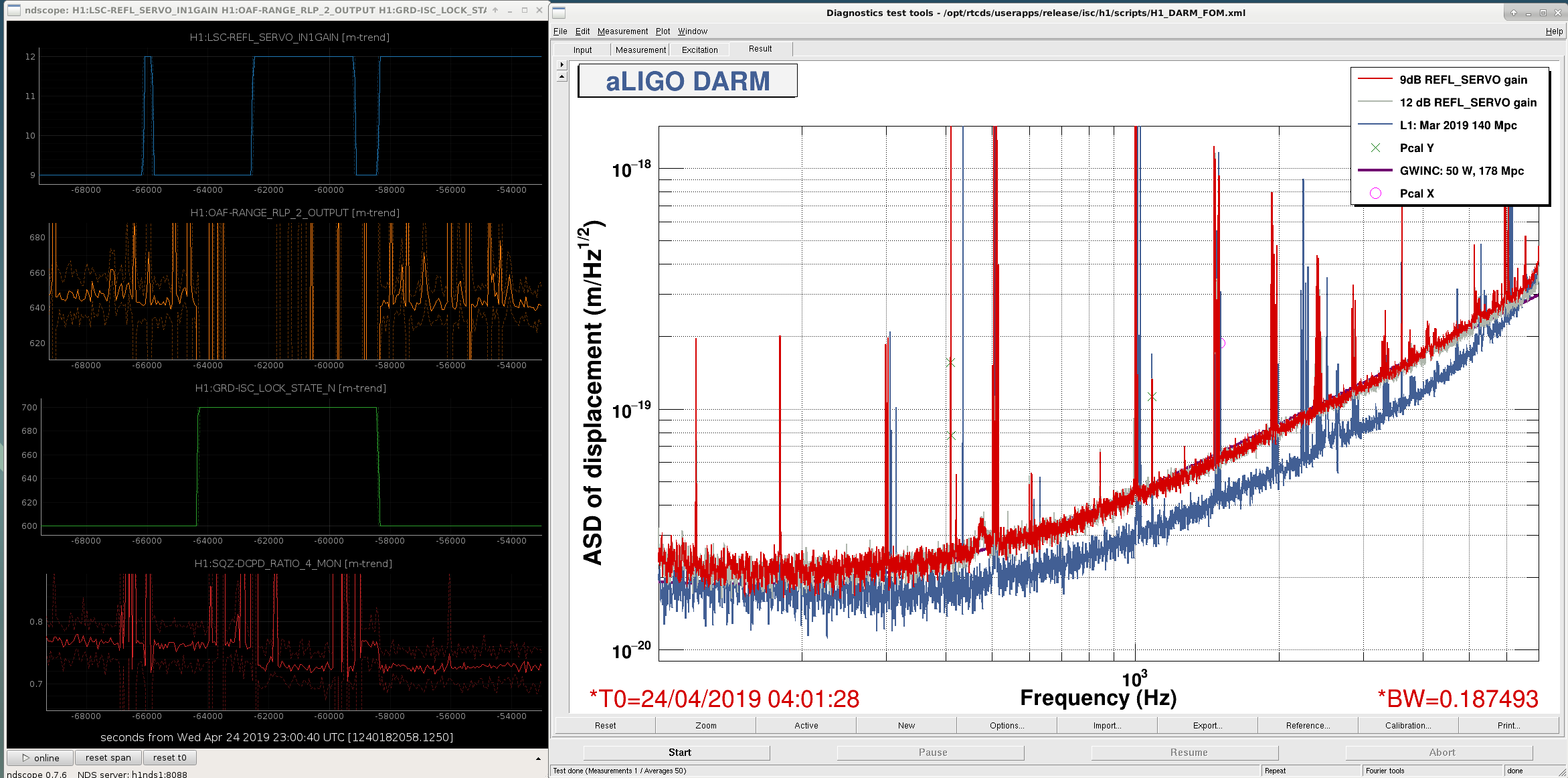
Attaching a screenshot shows DARM with the two LSC-REFL_SERVO_IN1 gains (grey = 12dB, red = 9dB). The improved frequency noise suppression is visible in DARM above 3.5 kHz, and also in the squeezer BLRMS (bottom time series), which looks at DARM at 4.68 kHz.
Additional CARM Spectra from 0.5 Hz to 5 MHz with the new changed configurations: CMB IN1 = +12 dB: REFL B : /ligo/home/craig.cahillane/Git/IFO/CARM/data/Spectra/StitchedSpectrum_20190425_REFL_B_35W_Input_CMBIN1_12dB.txt REFL A : /ligo/home/craig.cahillane/Git/IFO/CARM/data/Spectra/StitchedSpectrum_20190425_REFL_A_Spectrum_35W_Input_CMBIN1_12dB.txt CARM OUT2 : /ligo/home/craig.cahillane/Git/IFO/CARM/data/Spectra/StitchedSpectrum_20190425_CARM_OUT2_Spectrum_35W_Input_CMBIN1_12dB.txt IMC REFL : /ligo/home/craig.cahillane/Git/IFO/CARM/data/Spectra/StitchedSpectrum_20190425_IMC_REFL_Spectrum_35W_Input_CMBIN1_12dB.txt IMC TEST1 : /ligo/home/craig.cahillane/Git/IFO/CARM/data/Spectra/StitchedSpectrum_20190425_IMC_TEST1_Spectrum_35W_Input_CMBIN1_12dB.txt CMB IN1 = +6dB, CMB IN2 = +6dB (split control for REFL A and B) REFL B : /ligo/home/craig.cahillane/Git/IFO/CARM/data/Spectra/StitchedSpectrum_20190425_REFL_B_Spectrum_35W_Input_CMBIN1_6dB_CMBIN2_6dB.txt REFL A : /ligo/home/craig.cahillane/Git/IFO/CARM/data/Spectra/StitchedSpectrum_20190425_REFL_A_Spectrum_35W_Input_CMBIN1_6dB_CMBIN2_6dB.txt Posted are the comparison spectra of the three configurations of CARM we've been playing with:We can see that the CARM loop is gain limited at ~2kHz, since the REFL B spectrum decreased from increasing the CARM gain (Dark blue vs Light Blue). We can also see that REFL shot noise is dominating the spectrum from 3kHz down, from the switch to split sensor control (Light blue vs Orange)
+9 dB, REFL A sensor controlling CARM +12 dB, REFL A sensor controlling CARM +12 dB, Split REFL A and B sensors (+6 dB on each of the CMB Inputs)
J. Driggers, J. Kissel, L. Sun
Today, during the calibration measurement time, we've done the following:
(1) Tuned the calibration line heights such that the uncertainty of each line is now roughly 0.2%.
2019-04-17_TuningCalibrationLineAmplitudes_Uncertainty.png shows the time series of the uncertainty for all calibration lines over many hours before and after the line amplitude change -- the middle section is where they were turned off for the standard suite of calibration sweeps; before they were at their former value, after they were at their current value.
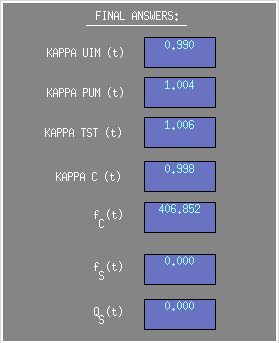
(2) We realized the discrepancy between GDS production of kappa_C (the relative optical gain correction) and f_cc (the cavity pole frequency) and CAL-CS was because in the heat of battle yesterday, we neglected to update the value of the necessary one clock-cycle delay to 410.3 Hz in the PCAL DEMOD -- i.e. it errantly remained as the delay value at the former calibration line frequency at ~331 Hz. Fixing this error returned the time-dependent correction factors to the expected values from the reference model: kappa_C = 1.00 +/- 0.01, and f_cc = 410.6 +/- a few Hz (as opposed to the brief period yesterday between after the calibration line frequencies and now, where the cavity pole was reporting in the 425 Hz region, and the optical gain correction was reporting 0.97).
2019-04-17_FixingPCALDEMODPhase_410Hz_Fixes_TDCFs.png shows a screenshot of the current values.
(3) We gather a collection of broad-band PCAL injections, as well as the standard sensing function sweeps.
Times of broad-band PCAL injections: 2019-04-17 20:13:20 UTC for ~2 minutes, and again at Apr 17 2019 20:15:31 UTC.
/ligo/svncommon/CalSVN/aligocalibration/trunk/Runs/O3/H1/Measurements/FullIFOSensingTFs
2019-04-17_H1_DARM_OLGTF_SS_5to1100Hz_15min.xml
2019-04-17_H1_PCAL2DARMTF_BB.xml
2019-04-17_H1_PCAL2DARMTF_SS_5t1100Hz_10min.xml
The data remains remarkably consistent with the reference model (see 2019-04-17_H1_sensingFunction_mcmcModel_vs_measurement.pdf ).
We've stacked all the recent sensing function measurements without correcting for time dependence to form an estimate of the frequency dependent, time-independent systematic erro with a Gaussian process regression, and it shows the same consistency (see 20190416_ref_model_H1_sensingFunction_GPR_on_AllSensingMeasurements.pdf)
More details to come.
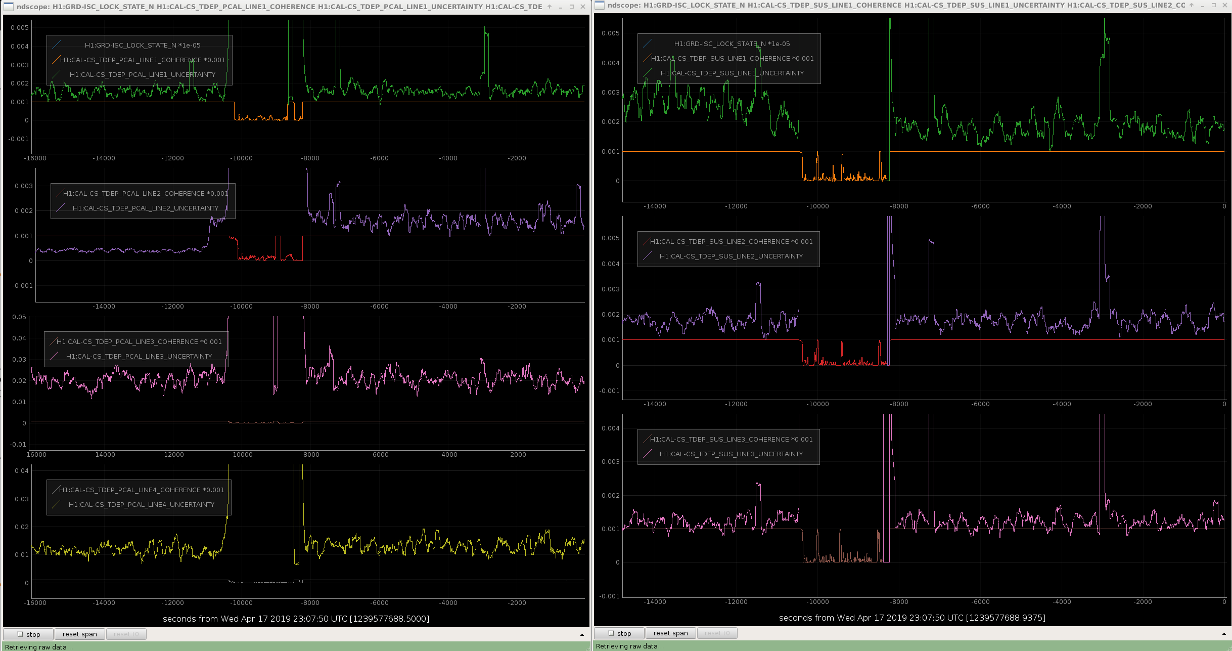
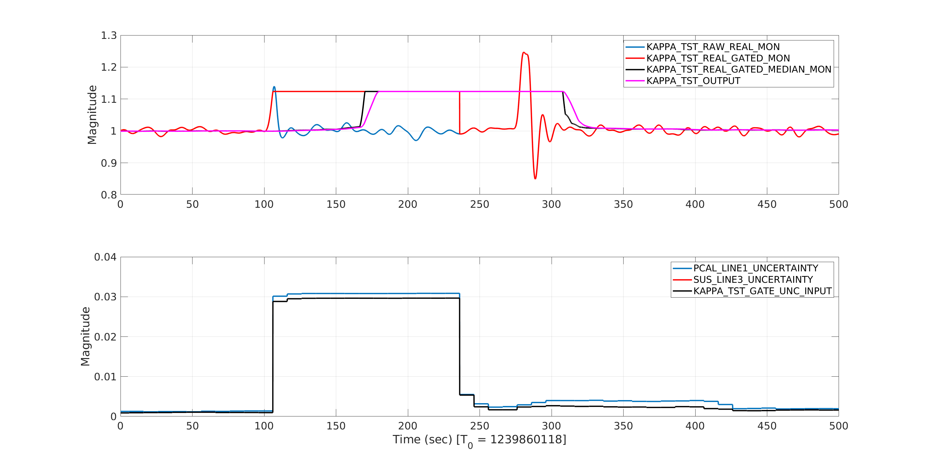
Here is a look at one of the excursion that happened in the front-end estimation of kappa_tst (first one seen in this summary page). The attached plot show various estimations of kappa_tst that happens in the front-end. It also show uncertainty estimation in the calculation of calibration line ratios. We see that when the uncertainty in the estimation of calibration line ratios exceeds set threshold of 0.02, it triggers the gating function. Since the glitch happened to be in the DARM_ERR (IFO) both PCAL_LINE1/DARM_ERR and TST/DARM_ERR ratios get uncertainties higher than 0.02 as in this case. The KAPPA_TST_GATE_UNC_INPUT which is finally used, according to model, supposed to be maximum of the two uncertainties but in this case it is the minimum of the two (KAPPA_TST_GATE_UNC_INPUT is on top of SUS_LINE3_UNCERTAINTY). Since it is still larger than 0.02, gating is triggered. However the gated kappa_tst values don't make any sense. It supposed to be avoid the excursion in the raw kappa_tst but it seems to change the level values of kappa_tst. This function need to checked (this is a user defined c function block). The signals after that make sense.
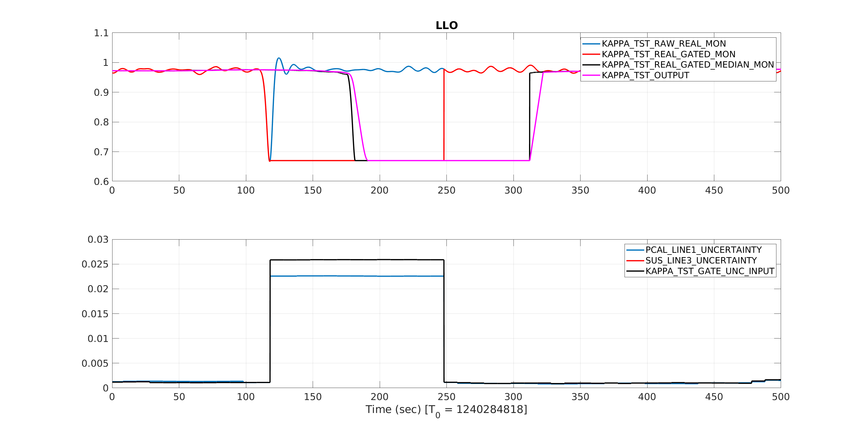
Similar plot for LLO which also show similar problem with gating function block.
Turns out the switch blocks used were defaulting to a logic comparison of >= 0 instead of > 0. Which means the first input was always being passed. I'll update this in the common CAL_CS_MASTER.mdl file and we should be able to push that next Tuesday. The gating issue is a bit trickier. As far as I can tell the gate is doing what its supposed to do. At the time the uncertainty rises above threshold, it freezes then and there as shown in Shivaraj's plots. The problem is, since the uncertainty calculation is basically on a cadence of 10 seconds, there's a 10 second gap between the demodulated low pass starting to respond to a large excursion and the I think this means we need to put 10 seconds (or maybe a touch longer) buffer between the kappa value input to the gate, so that the coherence corresponds represents the data coming in instead of data that came in during the last 10 seconds. A 163840 or so sample ring buffer is doable, but I'll have to modify a C code user block to do so.