I'm checking the coil driver switching while we wait for the earthquake to ring down, to ensure that the analog switches are actually switching. Here's a rough note of my method:
* Set BIO state request to negative of the value that you want (i.e. -2 for state 2, -3 for state 3). This gives you control of the coil out filter banks (ex. H1:SUS-ITMX_L2_COILOUTF_UL). Do this for all 4 quadrants.
* Turn off all filters, so you have a flat digital TF from the excitation point to the driver. Do this for all 4 quadrants.
* For BS (only one with oplev damping), disable oplev damping.
* Take TF from coil output filter bank excitation to fastimon channel (ex. H1:SUS-ITMX_L2_COILOUTF_UL_EXC to H1:SUS-ITMX_L2_FASTIMON_UL_OUT).
* Switch analog coil driver state, retake TF, confirm that it changed as expected.
* Put state request back to positive number that it started at; this resets the digital filters appropriately.
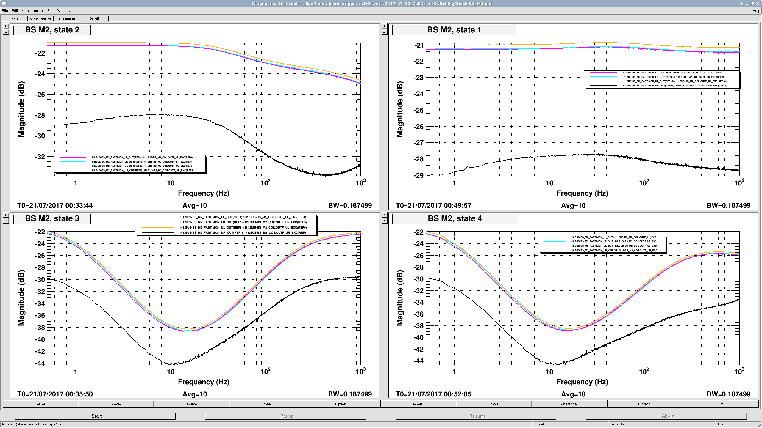
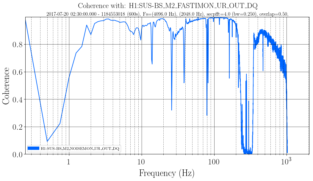
All switching seems fine for PRM M3, SRM M3, ITMX L2, ITMY L2, ETMX L2 and ETMY L2, which is all suspensions and stages that we switch coil driver states for, except for BS M2. BS M2's UR coil is different from the other coils on BS M2.
I'm attaching a screenshot of the BS measurements, showing that the shape of the UR analog driver is slightly different in each state, and the overall gain is different by about 8dB.
I ask that the BS M2 coil driver be looked at first thing in the morning.