Attempting to get the best tilt subtracted ground motion for sensor correction to the ISI has a seismometer piggy backing on the BRS Platform. However, seismometer difficulties lead to testing other STS2s. Still, our 'extra' STSs were not doing as well as we would like. So, we pulled our one spare T240 from storage and ran it on the floor nearby. It was then moved into the BRS enclosure replacing the STS there but low frequencies were noisier than when on the floor. On Tuesday, the Legs of the Table bolted to the BRS platform, on which the T240 sits, were insulated with 3/4" closed cell foam.
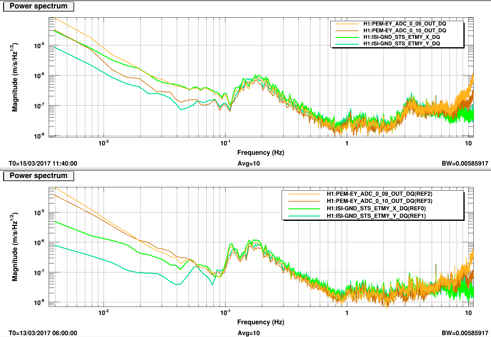
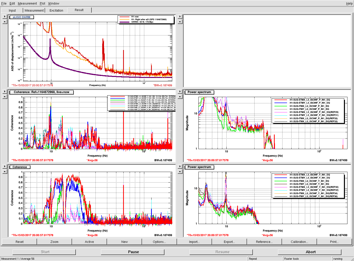
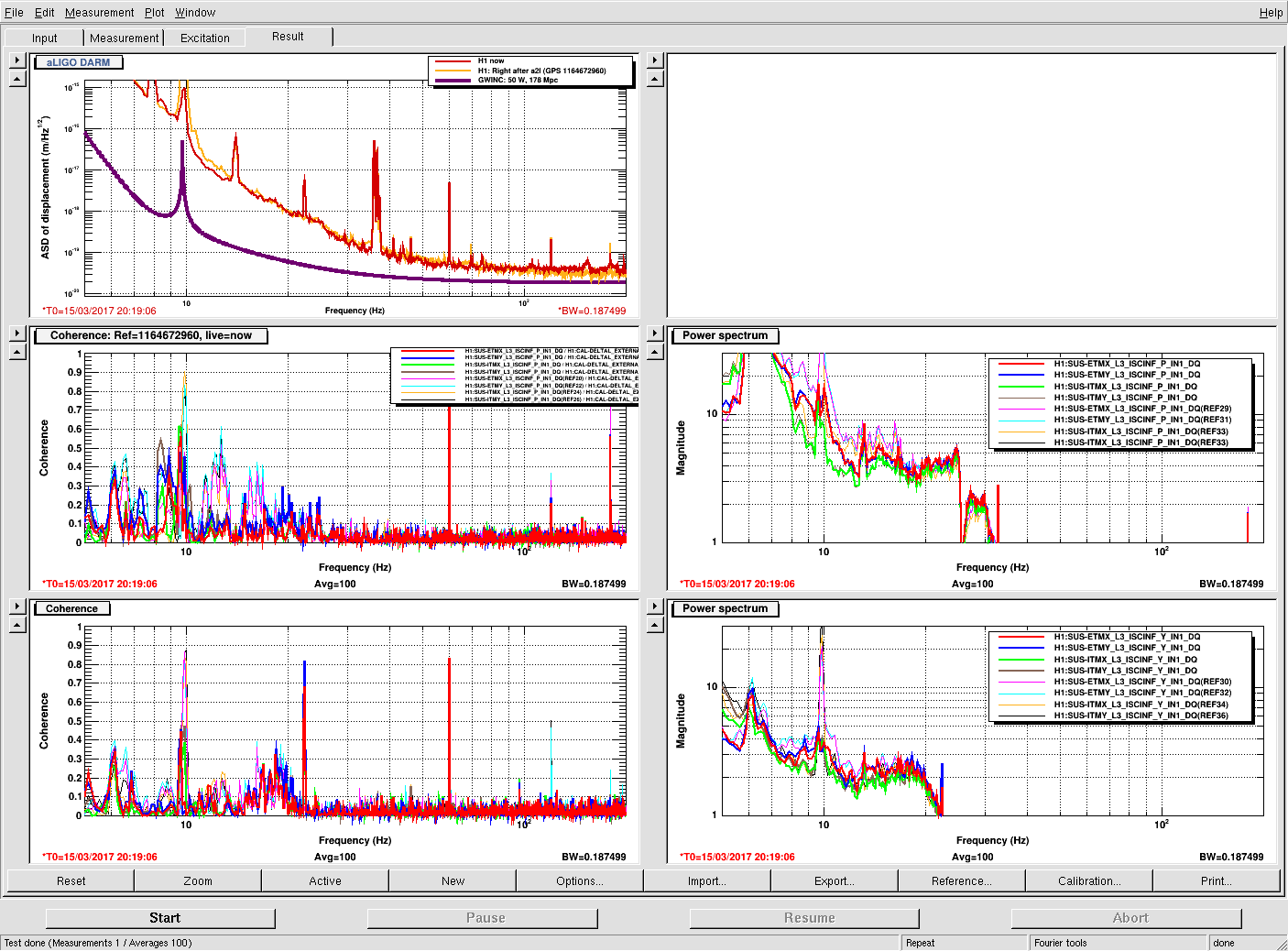
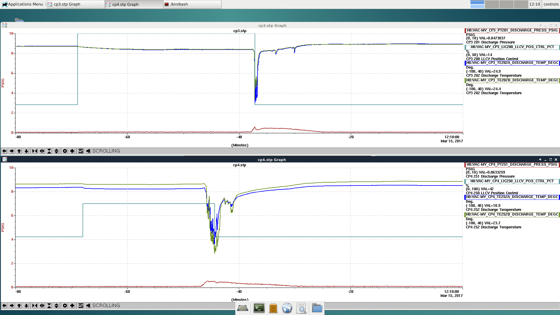
Krishna has looked and reports a factor of 3 improvement in the ASD and the coherence with the BRS is better. Here attached is before and after spectra comparing the ground seismometer X & Y with the T240 (ADC channels). The bottom plot has references from 0600utc 13 March before the Tuesday maintenance insulation addition. The upper plot with current traces are from 1140utc on 15 March (Cool! I did not know DDT would display the T0 of the reference traces, I guess as long as you have no current measurement traces displayed. 19 years and still something to learn!) We haven't had a low wind time since Maintenance basically so the comparison is not ideal.
Even with the larger ground motion, the Y axis of the now insulated T240 is quieter than before everywhere below 100mHz and closer to the well insulated ISI_STS nearby. The X axis is noisier but matches the GND STS down to 20mHz, much better than before. The winds have been about South 50degrees West (hitting the SW crane corner and that may rile up the X axis much more than the Y direction. Since this temperature sensitivity was apparently a large part of our low frequency noise problem, we'll look at other items in the BRS enclosure and the enclosure itself for thermal improvements.