LiyuanZ, PeterK, BetsyW, AlenaA, RickS (with support from EddieS, CalumT, StephenA, DennisC, GarilynnB, MalikR, et al.)
Some time ago, LLO removed PMC SN08 from operation due to a glitchy PZT.
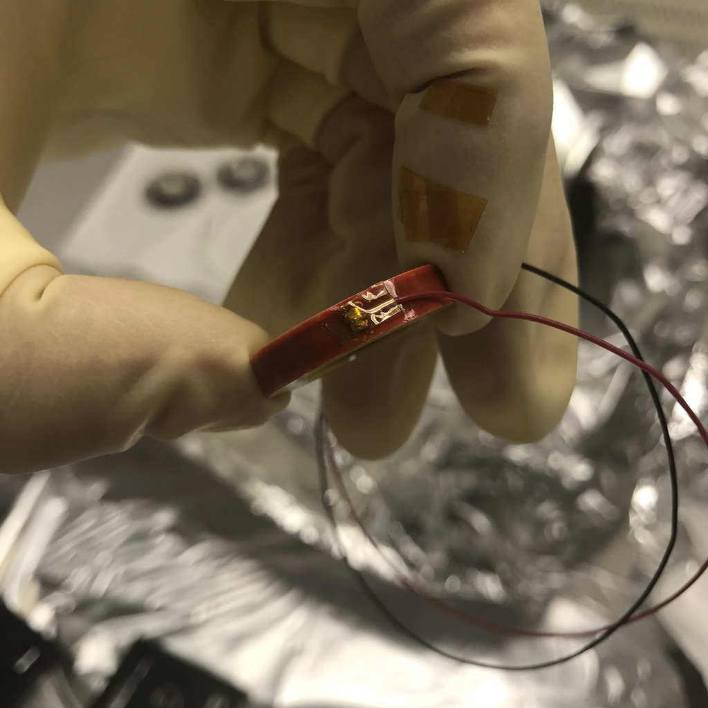
We recently removed and replaced the PZT and the curved mirror it actuates, using an original-style PZT ordered by Pking and a spare mirror from the original PMC mirrors (supposedly) provided by BennoW.
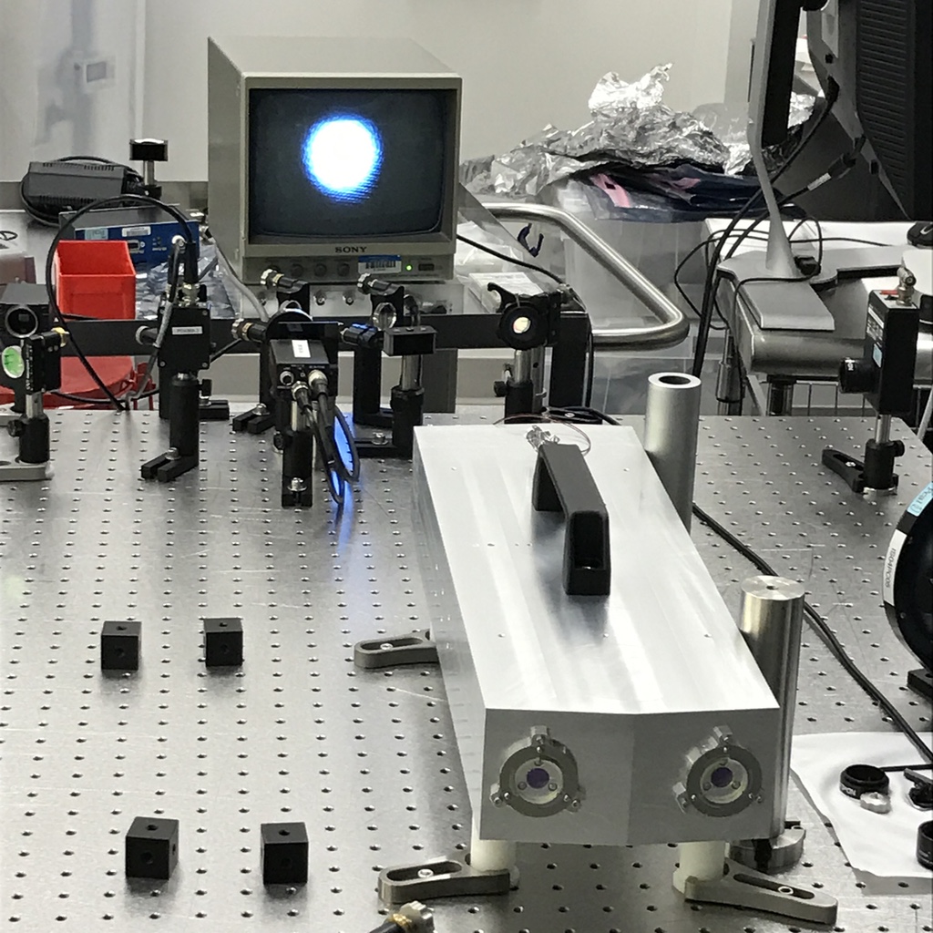
We characterized the losses in the cavity using a setup in the LHO "Triples Lab" (upper floor of Staging Building) that utilizes an NPRO and three Pcal-style integrating spheres and associated photodetectors (see LIGO-T1600204-v3).
We made some improvements to our measurement setup that preclude direct comparisons of the estimated losses before and after replacing the M4 mirror, but we estimate that the total round trip losses were reduced by about a factor of two by replacing the one mirror (investigations of other highly contaminated PMC indicate that the PZT is the source of the contaminants and that the mirror bonded to the PZT is the most contaminated).
Our current best estimate of the average losses per mirror for this cavity is about 60 ppm (see attached table).
We were surprised to find that the transmitted light level through M4 is about 40 times smaller than M3. The spec for the M3 and M4 transmission is 60 ppm and we calculate the M3 transmission to be about 65 ppm, but the M4 transmission of only 1.6 ppm is a mystery. It doesn't seem it was from the same coating run, as expected. However, discussions with DanielS indicated that this might be acceptable. The M4 transmitted light is used for the ISS path and is typically attenuated by about a factor of 100 on the PSL table.
We also tested a new concept for fabricating the PMCs that relies on machining tolerances for setting the orientation of the four cavity mirrors and eliminates all gluing from the assembly. Two original PMC bodies were re-machined at a local machine shop in a single setup with the hope of achieving relative accuracy between the points on which the cavity mirrors register on the level of 5 micrometers.
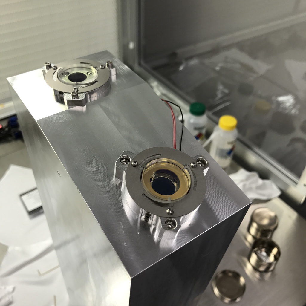
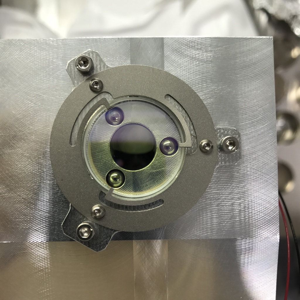
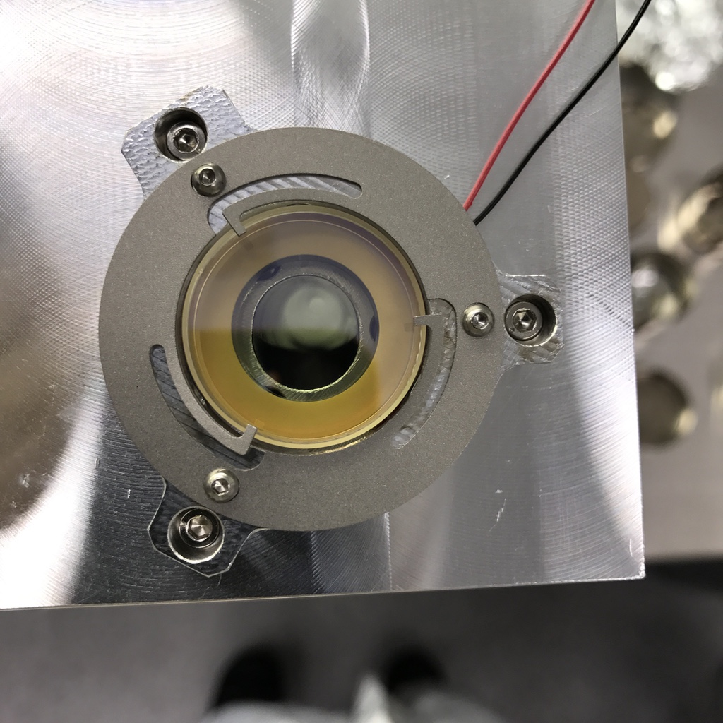
We assembled both "all-bolted" prototypes under a clean bench by mounting the mirrors against three balls that register at the bottoms of counterbores in the aluminum bodies and holding the mirrors (and the sandwiched PZT) in place using off-the-shelf SS flexures (see attached photos). We used mirrors recently procured by PeterK from ATF.
We discovered that there was an error in the coating of the new PMC flat mirrors; the reflectivity is only 2,400 ppm when it was supposed to be 24,000 ppm. Thus the cavity finesse is 10x higher than desired. While this won't work for the PSL, it aids in measuring the mirror losses. The results of two measuremens are tabulated in the attached table for the S/N10 body. The average losses per mirror are estimated to be about 11 ppm. We have not measured the losses for the other "all-bolted" cavity yet.
These measurements confirm the abiltiy to machine the bodies to the required tolerances. We will test the PZT performance as best we can in our lab setup when time allows.