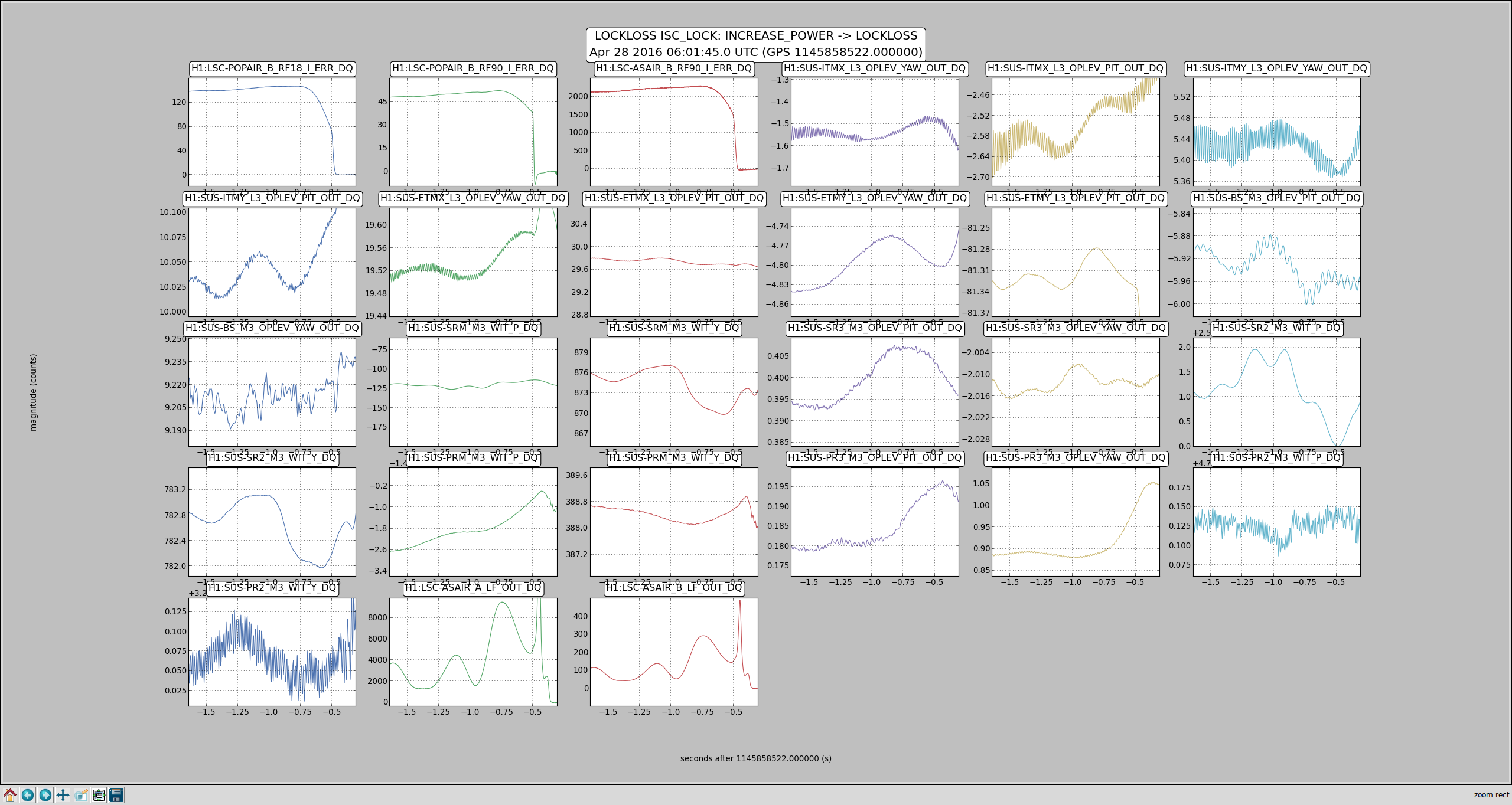
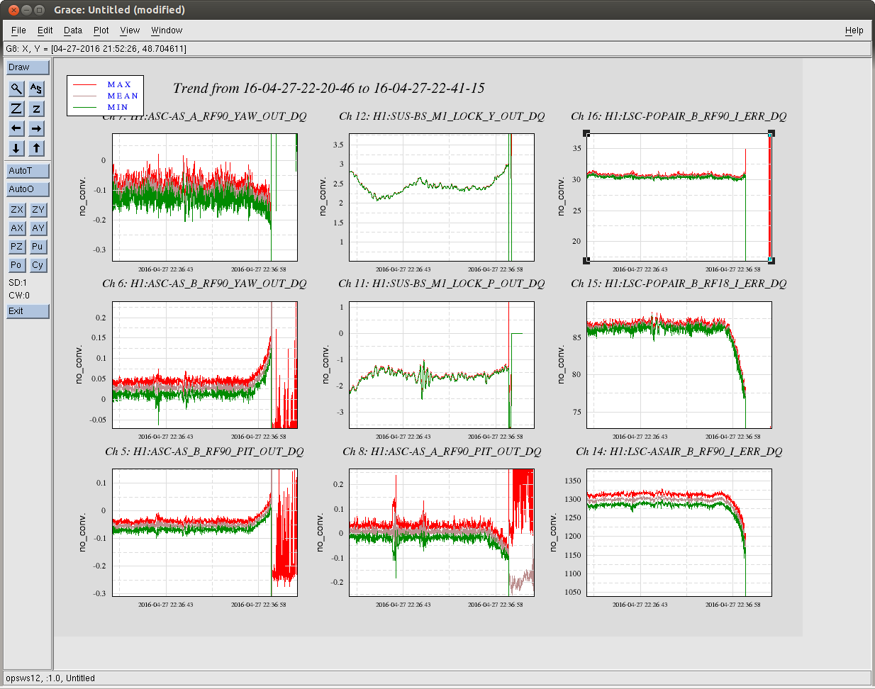
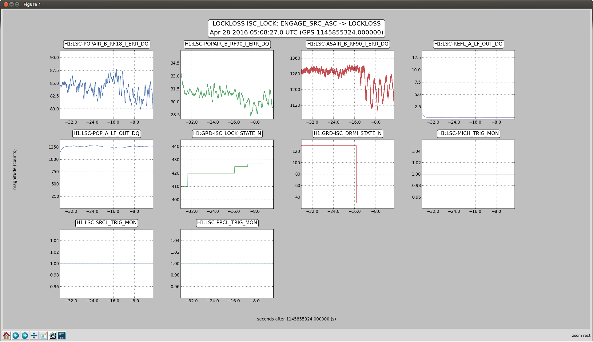
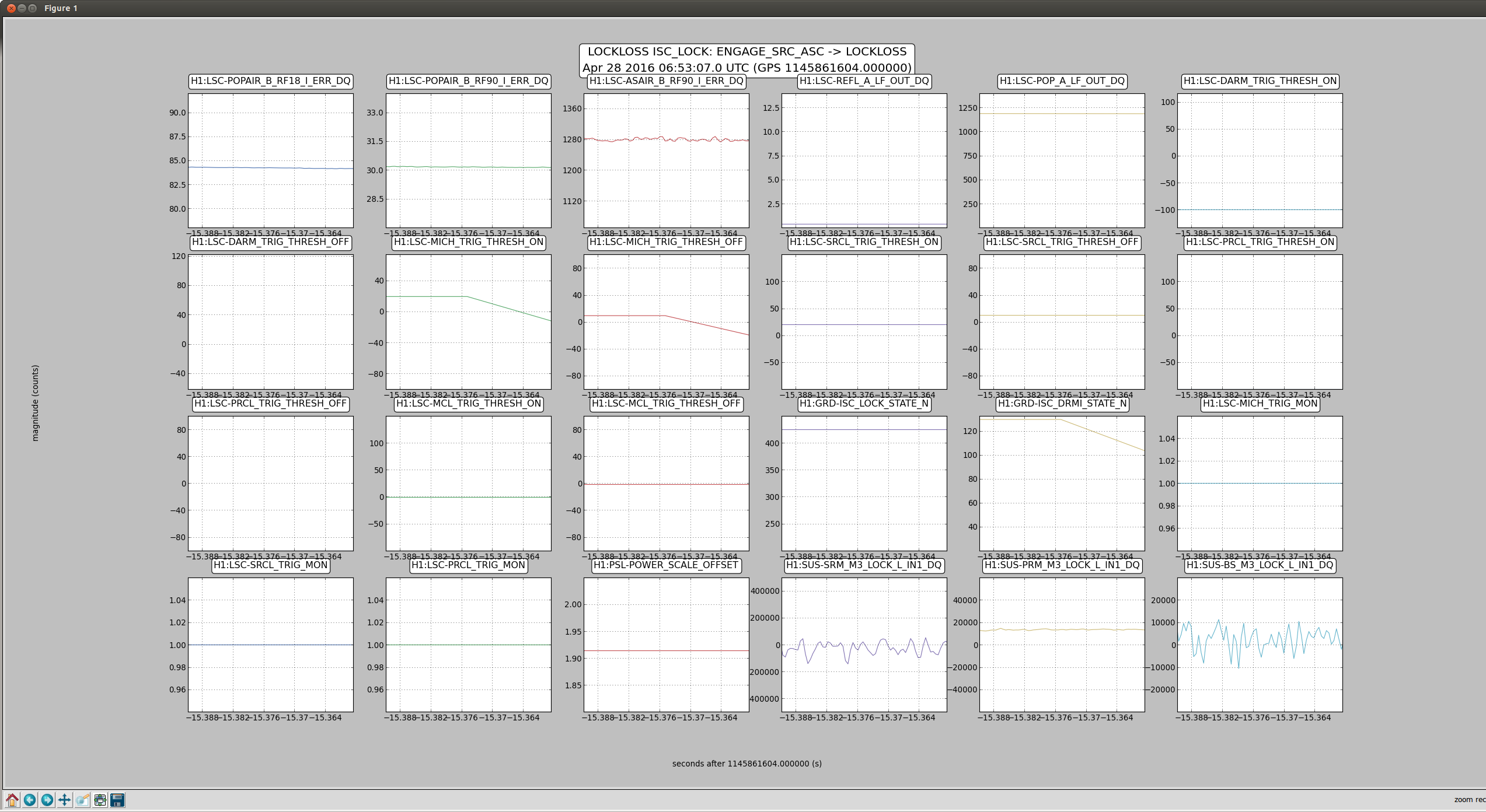
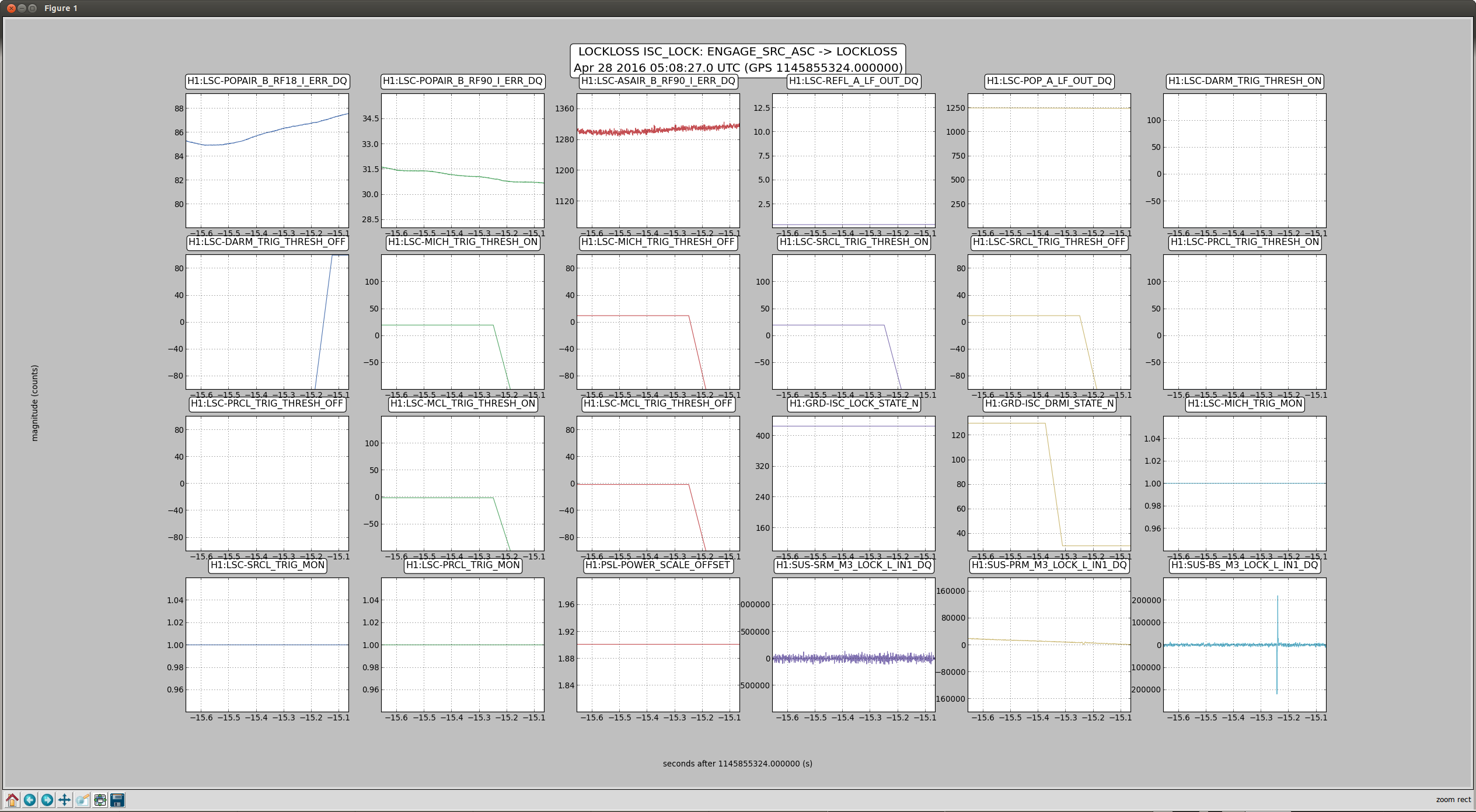
Elli and Stefan showed in aLOG 20827 that the signals measured by AS 36 WFS for SRM and BS alignment appeared to be strongly dependent on the power circulating in the interferometer. This was apparently not seen to be the case in L1. As a result, I've been looking at the AS 36 sensing with a Finesse model (L1300231), to see if this variability is reproducible in simulation, and also to see what other IFO variables can affect this variability.
In the past when looking for differences between L1 and H1 length sensing (for the SRC in particular), the mode matching of the SRC has come up as a likely candidate. This is mainly because of the relatively large uncertainties in the SR3 mirror RoC combined with the strong dependence of the SRC mode on the SR3 RoC. I thought this would therefore be a good place to start when looking at the alignment sensors at the AS port. I don't expect the SR3 RoC to be very dependent on IFO power, but having a larger SR3 RoC offset (or one in a particular direction) may increase the dependence of the AS WFS signals on the ITM thermal lenses (which are the main IFO variables we typically expect to change with IFO power). This might therefore explain why H1 sees a bigger change in the ASC signals than L1 as the IFOs heat up.
My first step was to observe the change in AS 36 WFS signals as a function of SR3 RoC. The results for the two DOFs shown in aLOG 20827 (MICH = BS, SRC2 = SRM) are shown in the attached plots. I did not spend much time adjusting Gouy phases or demod phases at the WFS in order to match the experiment, but I did make sure that the Gouy phase difference between WFSA and WFSB was 90deg at the nominal SR3 RoC. In the attached plots we can see that the AS 36 WFS signals are definitely changing with SR3 RoC, in some cases even changing sign (e.g. SRM Yaw to ASA36I/Q and SRM Pitch to ASA36I/Q). It's difficult at this stage to compare very closely with the experimental data shown in aLOG 20827, but at least we can say that from model it's not unexpected that these ASC sensing matrix elements are changing with some IFO mode mismatches. The same plots are available for all alignment DOFs, but that's 22 in total so I'm sparing you all the ones which weren't measured during IFO warm up.
The next step will be to look at the dependence of the same ASC matrix elements on common ITM thermal lens values, for a few different SR3 RoC offsets. This is where we might be able to see something that explains the difference between L1 and H1 in this respect. (Of course, there may be other effects which contribute here, such as differential ITM lensing, spot position offsets on the WFS, drifting of uncontrolled DOFs when the IFO heats up... but we have to start somewhere).
Can you add a plot of the amplitude and phase of 36MHz signal that is common to all four quadrants when there's no misalignment?
As requested, here are plots of the 36MHz signal that is common to all quadrants at the ASWFSA and ASWFSB locations in the simulation. I also checked whether the "sidebands on sidebands" from the series modulation at the EOM had any influence on the signal that shows up here: apparently it does not make a difference beyond the ~100ppm level.
At Daniel's suggestion, I adjusted the overall WFS phases so that the 36MHz bias signal shows up only in the I-phase channels. This was done just by adding the phase shown in the plots in the previous comment to both I and Q detectors in the simulation. I've attached the ASWFS sensing matrix elements for MICH (BS) and SRC2 (SRM) again here with the new demod phase basis.
**EDIT** When I reran the code to output the sensitivities to WFS spot position (see below) I also output the MICH (BS) and SRC2 (SRM) DOFs again, as well as all the other ASC DOFs. Motivated by some discussion with Keita about why PIT and YAW looked so different, I checked again how different they were. In the outputs from the re-run, PIT and YAW don't look so different now (see attached files with "phased" suffix, now also including SRC1 (SR2) actuation). The PIT plots are the same as previously, but the YAW plots are different to previous and now agree better with PIT plots.
I suspect that the reason for the earlier difference had something to do with the demod phases not having been adjusted from default for YAW signals, but I wasn't yet able to recreate the error. Another possibility is that I just uploaded old plots with the same names by mistake.
To clarify the point of adjusting the WFS demod phases like this, I also added four new alignment DOFs corresponding to spot position on WFSA and WFSB, in ptich and yaw directions. This was done by dithering a steering mirror in the path just before each WFS, and double demodulating at the 36MHz frequency (in I and Q) and then at the dither frequency. The attached plots show what you would expect to see: In each DOF the sensitivity to spot position is all in the I quadrature (first-order sensitivity to spot position due to the 36MHz bias). Naturally, WFSA spot position doesn't show up at WFSB and vice versa, and yaw position doesn't show up in the WFS pitch signal and vice versa.
For completeness, the yaxis is in units of W/rad tilt of the steering mirror that is being dithered. For WFSA the steering mirror is 0.1m from the WFSA location, and for WFSB the steering mirror is 0.2878m from the WFSB location. We can convert the axes to W/mm spot position or similar from this information, or into W/beam_radius using the fact that the beam spot sizes are at 567µm at WFSA and 146µm at WFSB.
As shown above the 36MHz WFS are sensitive in one quadrature to spot position, due to the constant presence of a 36MHz signal at the WFS. This fact, combined with the possibility of poor spot centering on the WFS due to the effects of "junk" carrier light, is a potential cause of badness in the 36MHz AS WFS loops. Daniel and Keita were interested to know if the spot centering could be improved by using some kind of RF QPD that balances either the 18MHz (or 90MHz) RF signals between quadrants to effectively center the 9MHz (or 45MHz) sideband field, instead of the time averaged sum of all fields (DC centering) that is sensitive to junk carrier light. In Daniel's words, you can think of this as kind of an "RF optical lever".
This brought up the question of which sideband field's spot postion at the WFS changes most when either the BS, SR2 or SRM are actuated.
To answer that question, I:
Some observations from the plots:
I looked again at some of the 2f WFS signals, this time with a linear sweep over alignment offsets rather than a dither transfer function. I attached the results here, with detectors being phased to have the constant signal always in I quadrature. As noted before by Daniel, AS18Q looks like a good signal for MICH sensing, as it is pretty insensitive to beam spot position on the WFS. Since I was looking at larger alignment offsets, I included higher-order modes up to order 6 in the calculation, and all length DOFs were locked. This was for zero SR3 RoC offset, so mode matching is optimal.
The DMT (GDS) code (including the gstlal calibration code) was updated this morning around 9:18 am PDT. There were several restarts after that, but DMT hoft generation has running stably since 1126979632 == Sep 22 2015 10:53:35 PDT
(John Zweizig and Maddie Wade still need to double check that the correct code and command line options are being used, though John did do an initial check.)
15:00 Pepsi trucks on site
Christina checking out bidgs
15:02 Jeff: Dust Monitor work
15:35 Fil, Andreas, and Leslie to CER, LVEA to take pictures of the racks.
15:41 Hugh left X end
Patrick to MidY to look for spare Bekhoff
Bubba out of LVEA
15:43 Jodi out of LVEA
15:46 Jeff added 150 mL to PSL chiller
15:49 Jason to Mid X to check on 3IFO Oplev spare
15:51 Praxxair on site - one to EX driving real slow.
Bubba using forklift to move the barricades
16:03 Patrick back
Richard just finished w/ the vault. Heading to Mid X.
Fire department here to test fire hydrant.
Spotted Praxxair at Mid Y. Apparenlt there are two Praxxair trucks.
16:09 Christina + Karen to EX and EY. Just to look. No cleaning.
16:13 Peter to change room to take pictures of the eyewares.
Sheila and Keita checking on Fil at CER.
16:20 Jason out
16:24 Peter done in the change room.
16:27 Richard back
16:39 Mitchell + Hugh checking on 3IFO stuff at North bay
16:42 Karen + Christina leaving EY
Fire department to EY
16:47 Mike + SPIE camera crew out of LVEA
16:50 Richard to EY and MY to pick up Beckhoff stuff
16:51 Bubba to fan room to work on Sf3
16:57 Mike + SPIE crew driving down X arm
17:11 Joe done checking extinguisher (EX, EY, LVEA)
17:14 Richard back
17:18 Mike back
17:19 Daniel pulls some quipment out of electronics room
17:25 Fil to EX
17:32 Daniel out
17:52 Hydrant shut off at corner station
17:53 Jeff B. to mezzanine area
17:54 Jim restart H1 nds0 and nds1
17:44:35-17:55:47 Lots of ETMY saturations
18:05 Kyle starting pumps at MY (leak detection)
18:11 Fil and Andreas at EY
18:12 Cheryl and Ed doing LVEA sweep
18:20 Dave restart broadcaster
18:24 Hugh to both end stations to photograph stuff
18:30 Jeff B. out. And ging to bring up roll up door 3 feet to move in boxes (not heavy).
18:35 Evan and Jenne to LVEA (ISC rack)
18:37 Hugh at EX. Ken drilling hole on the beam tube concrete
18:05:36-18:34:34 Hell of ETMY saturations
18:41 Jeff B. done. He also added water to TCS chiller =D
18:45 Evan and Jenne out
18:46 Fil to EY to pickup stuff.
19:01 Hugh at EX. Fil just left EX.
19:07 Fire guy done checking extinguisher.
WP #5495 The raw minute trend files created by the trend writers (h1tw0, h1tw1) have been moved to prepare for copying. This required the restart of daqd on h1nds0, h1nds1 so the nds servers can find the old files. This is a combination of routine maintenance and recovery from the loss of raw minute trend files on h1tw0 when the SSD RAID system failed. The preserved raw minute trend files will now be copied to the SATABoy RAIDs for both h1nds0 and h1nds1.
J. Kissel I've increased the actuation delay before the sum of the the RESIDUAL (sensing) and CTRL (actuation) paths in the CAL-CS reproduction of H1:CAL-CS_DARM_DELTAL_EXTERNAL from four 16 [kHz] clock cycles (244 [us]) to seven 16 [kHz] clock cycles (427 [us]). This is done by changing the H1:CAL-CS_DARM_CTRL_DELAY_CYCLES EPICs record. The change is motived in LHO aLOG 21746. Recall this only affects the reproduction of the DARM displacement signal H1:CAL-CS_DARM_DELTAL_EXTERNAL (and therefore its ASD projected on the wall). I attach screenshots of the before and after. Note that the ASDs were taken ~30 minutes apart, so I don't expect the detailed structure to be the same. However, the change in phase at the sensing / actuation cross over causes overall shap change in the bucket. Also note that the transfer function used to remove the systematics from the DELTAL EXTERNAL channel will now have to be updated (documented in LHO aLOG 20481), to avoid double counting the high frequency affects. In the attached ASD, those corrections have *not* been changed, so we are likely double counting the corrections. More on that after I reconcile what Kiwamu had done and what Peter suggests. I've captured the updated setting in both the OBSERVE.snap and SAFE.snap SDF files, and committed each to the repository.
I've updated the slide I'd made in the PreER7 -era that elucidates all of the time delays and approximations that we've made to come up with the seven 16 [kHz] clock-cycle delay between the actuation path and sensing path. The ER7 version is pg 7 of G1500750. See attached. In summary, the total delay *between* the inverse sensing and actuation chains, if we approximate all high-frequency frequency response as delays that are in addition to the "true" delays from computer exchanges, if we weren't limited by 16 [kHz] clock cycles should be 442.6 [us]. Because we are limited to 16 [kHz] clock cycles, we've chosen 7, which is a delay of 427.3 [us] -- a 15.3 [us] systematic error. You should also remember, that having this delay between the chains means that CAL-CS_DELTAL_EXTERNAL has an overall delay or "latency" equivalent to that of the inverse sensing function advance, which is 213.6 [us]. Note that these numbers are LHO-centric -- the approximation for the OMC DCPD signal chain of 40 [us] assumes the pole frequencies of the H1 OMC DCPD chain, and the estimation of the systematic error in phase uses H1's DARM unity gain frequency of 40.65 [Hz]. For LLO, the details should be redone if a precise answer is needed.
Dave Barker, TJ
The new version of ext_alert.py (the scripts that polls GraceDB and reports events) is now running here at LHO. It has been running at LLO while they tested it and we got the OK from Duncan Macleod today. This new version will alert for "E" type events and now "G" type as well. The new events can be seen on the CAL_INJ_CONTROL.adl medm screen.
As a test, psinject is running excitations to the h1calcs model. Note that the actual injection is turned off using the hardware injection control MEDM screen. The psinject process is under control of Monit on h1hwinj1. This will be turned off at the conclusion of Tuesday maintenance.
The psinject has been stopped on h1hwinj1, and removed from monit control until it's ready to be installed permanently. We tried killing psinject to verify that monit could and would restart the process automatically, the test succeeded.
The following servers have been patched and rebooted: ldr.ligo-wa.caltech.edu ldas-pcdev2.ligo-wa.caltech.edu The following servers were patched but were not and will not be rebooted today: detchar.ligo-wa.caltech.edu all compute nodes (node[1-270], gpu-node[1-5])
We saw a large glitch in the RF AM monitors with high coherence with DARM at around 16:13 UTC on Sept 22nd, while the IFO was locked and maintence was happening. There werw people in the LVEA (though not near the PSL) and people in the CER but they were near the SEI and SUS racks, not the ISC racks. The first attached plot shows this on a 5 hour time scale, the second plot has 5 days. This can be compared to Evan's plots of the last 3 weeks (21766)
Starting around 2015-09-22 17:51:00 Z we had a few minutes or what appeared to be full-on instability of the RFAM stabilization servo. The control signal spectrum was >10× the typical value from 10 to 100 Hz. [Edit: actually, it looks like glitching; see below.]
I tried turning the modulation index down by as much as 1.5 dB, but there was no clear effect.
I've attached time series as a zipped DTT xml for the driver channls (control signal, error signal, OOL sensor) during such a glitchy period.
In the control signal, all the glitches I looked at have the same characteristic shape (see the screenshot with the zoomed time series): an upward spike, a slight decay, a downward spike, and then a slower decay back to the nominal control signal level.
The control signal during the Γ-reduction attempts seems quite smooth; the 0.2-dB steps do not produce glitches.
The full report can be found on the detchar wiki, but here are the main highlights:
TITLE: Sept 22, Day Shift: starting 15:00UTC
STATE Of H1: Locked/Commissioning, Range is 50+MPC, trying to stay locked for filter tests
OUTGOING OPERATOR: Corey
QUICK SUMMARY: Maintenance started at 15:00UTC. Many people/trucks on site and people in VEAs and in the LVEA. Attempting to stay locked for ASC filter tests: Sheila.
- Jeff, forklift, dust monitor, mechanical building and high bay
- Christina - out buildings, no real cleaning, but checking for problems
- Ken, hammering 250m from end stations
- Richard, vault
- Bubba, 3IFO checking storage, and placing cones to protect elec.
- Jodi, 3IFO checks
- Pepsi, two trucks, on site
- Hanford Fire, hydrant checks
- Hugh, checking HEPI fluid levels,
- Jim, troubleshooting hardware injections, may glitch...
- Joe, taking Fire Dept. guy through LVEA and both end stations
- Mike, film crew, LVEA
- Praxair is onsite, though came through the open gate, so I don't know where they are
- Sheila, loading filter, started 15:20UTC
- Sprague, spraying perimiter
TITLE: 9/22 OWL Shift: 7:00-15:00UTC (00:00-8:00PDT), all times posted in UTC
STATE OF H1: Observation Mode @ 70+Mpc, but getting ready for Maintenance
SUPPORT: None (& not needed)
SHIFT SUMMARY: Other than the Chilean aftershock, this was a stellar shift.
Incoming DAY Operator: Cheryl V.
SHIFT'S ACTIVITIES:
Just chatted with Brian and Jeremy at LLO about the start of their Maintenance time (which is usually 8amCT [13:00UTC]), and they said they are going to let L1 stay in Observation Mode beyond their usual Maintenance start time so we can have more double coincident time (they will let L1 drop out whenever activities/contractors bump it out of lock.)
(For the record, LHO's Maintenance Time starts at 8am PST [15:00UTC]).
13:32 UTC Guimin just notified me they are out of lock and starting their Maintenance.
Chris B., Jeff K. We performed a series of single-IFO hardware injections at H1 as a test. The intent mode button was off at the time. All injections were the same waveform from aLog 21744. tinj was not used to do the injections. The command line used to do the injections was: awgstream H1:CAL-INJ_TRANSIENT_EXC 16384 H1-HWINJ_CBC-1126257410-12.txt 0.2 -d -d awgstream H1:CAL-INJ_TRANSIENT_EXC 16384 H1-HWINJ_CBC-1126257410-12.txt 0.5 -d -d >> log.txt awgstream H1:CAL-INJ_TRANSIENT_EXC 16384 H1-HWINJ_CBC-1126257410-12.txt 0.5 -d -d >> log.txt awgstream H1:CAL-INJ_TRANSIENT_EXC 16384 H1-HWINJ_CBC-1126257410-12.txt 0.5 -d -d >> log.txt awgstream H1:CAL-INJ_TRANSIENT_EXC 16384 H1-HWINJ_CBC-1126257410-12.txt 1.0 -d -d >> log.txt I've attached the log (log.txt) which contains the standard output from running awgstream. Taken from the awgstream log the corresponding times are approximates of the injection time: 1126916005.002499000 1126916394.002471000 1126916649.002147000 1126916962.002220000 1126917729.002499000 The expected SNR the waveform is ~18. The scale factors applied by awgstream should change the SNR by a factor of 0.2 and 0.5 when used. I've attached timeseries of the INJ-CAL_HARDWARE and INJ-CAL_TRANSIENT. The injections did not reach the 200 counts limit of the INJ_HARDWARE filterbank that we saw in the past. Watching the live noise curve in the control room we did not notice any strong indication of ETMY saturation which usually manifests itself as a rise in the bucket of the noise curve. But this needs followup. I've attached omegascans of the injections.
It looks like there's a pre-injection glitch in the last spectrogram. Is that understood?
There were no ESD DAC overflows due to any of the injections. The only such overflow was at 1126916343, which was between injections. The glitch before the last injection is not understood. It does not correspond to the start of the waveform, which is at GPS time ___29.75. The glitch is at ___29.87 (see attached scan), and I can't find what feature in the waveform it might correspond to. It may be some feature in the inverse actuation filter. We should repeat this hardware injection to see if the glitch happens again. Subsequent injections should be done with a lower frequency of 15 Hz (this was 30 Hz), to make sure there are no startup effects. This will only make the injection about 3 seconds longer. In the above, I'm assuming that the hardware injection is always synchronized to the GPS second, so that features in the strain file correspond exactly to what is injected, with just an integer offset. I confirmed that by looking at the injection channel, but someone should correct me if the injection code ever applies non-integer offsets.
If you run awgstream without specifying a start time, it chooses a start time on an exact integer GPS second. (On the other hand, if you DO specify a start time, you can give it a non-integer GPS time and it will start the injection on the closest 16384 Hz sample to that time.)
Note that these CBC injections were recorded by ODC as Burst injections (e.g., see https://ldas-jobs.ligo-wa.caltech.edu/~detchar/summary/day/20150922/plots/H1-ALL_893A96_ODC-1126915217-86400.png) because the CAL-INJ_TINJ_TYPE channel was left at its previous setting, evidently equal to 2.
I completed LALInference followup of these events. linked from https://www.lsc-group.phys.uwm.edu/ligovirgo/cbcnote/aLIGOaVirgo/150827092943PEO1%20parameter%20estimation%20procedure#Hardware_Injections