This is a classic tale of IM1-3 woes - IM1-3 are very likely to move when the HAM2 ISI trips, so need to be checked every time.
The IMs come from IOO, so they are unlike any other optics we have, and so behave in a very different way, and are suscetable to changing alignment when they experience shaking, like they do when the ISI trips.
The IM OSEM values are consistant, and when the optic alignment shifts, it is consistantly recovered by driving the optic back to previous OSEM vlaues, regardless of slider values. The OSEM values, when restored, consistantly restore the pointing onto IM4 Trans QPD.
IM4 Trans QPD reads different values for in-lock vs out-of-lock, so it's necessary to trend a signal like OMC DC A PD to correctly compare times.
IM4 does sometimes shift it's alignment after shaking, but because it's moved around by the IFO, choosing a starting value can be difficult. In the case of IM4, restoring it's alignment to a recent out-of-lock value should be sufficient to lock, but ultimately IM4 needs to be pointing so that we can lock the X arm in red.
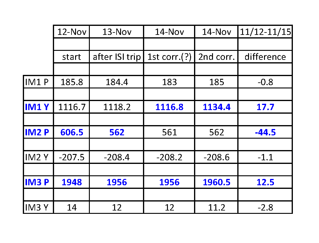
I've tracked the alignment changes for the IM1-3 since 9 Nov 2015, and they are listed below.
-
11/12, starting values, all optics change by only around 2urad for the previous 3 days (11/9-11/12)
-
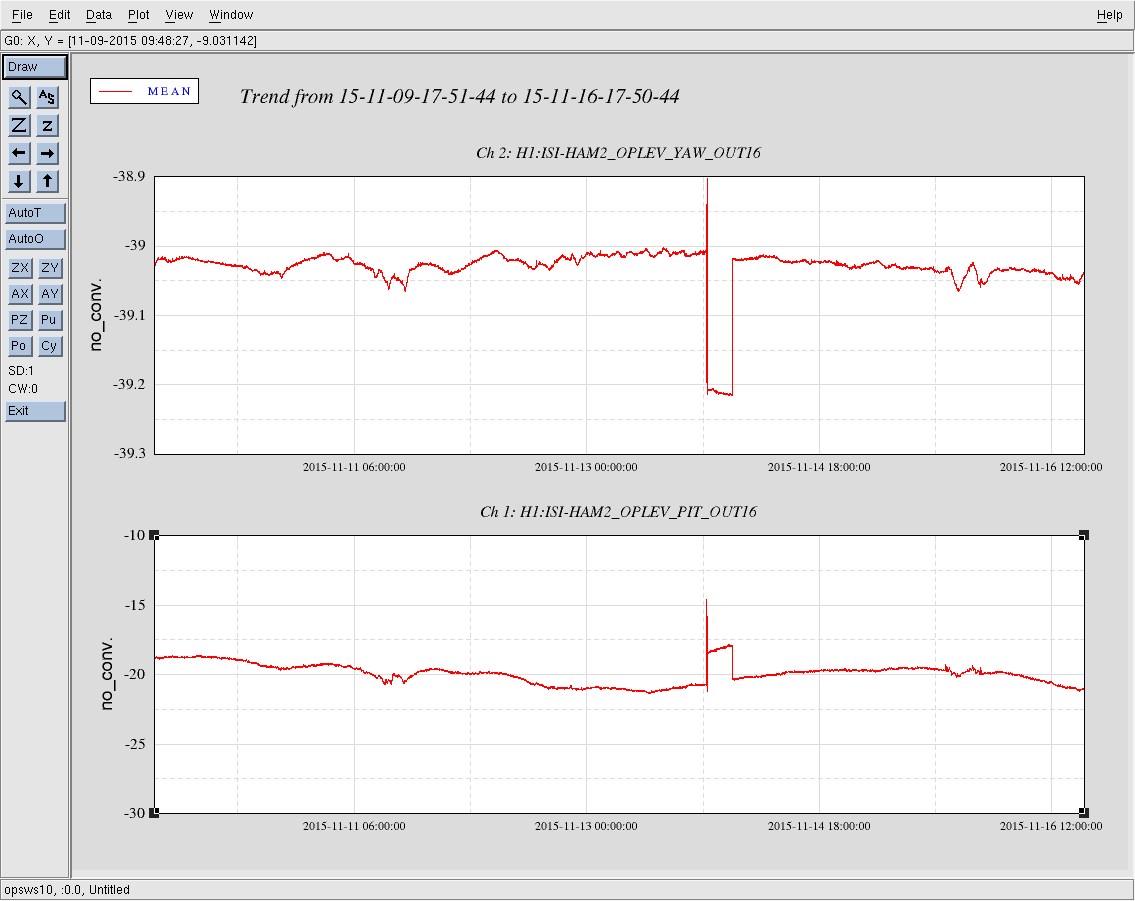
11/13, the ISI tripped, and IM2 Pitch changed by 40urad, and IM3 Pitch changed by 8urad
-
11/14, around 00:30UTC, there's a clear step in signals, but alignment is unchanged, possible 1st attempt at correcting alignment (?)
-
11/14, around 23:45UTC, an alignment correction, however optics do not retun to starting values
These alignment changes are big enough to effect locking, and it's possible that the IFO realignment that was necessary last night was in part a response to IM pointing changes.
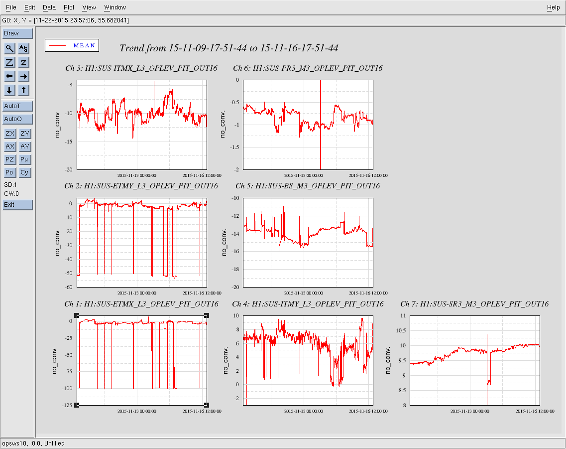
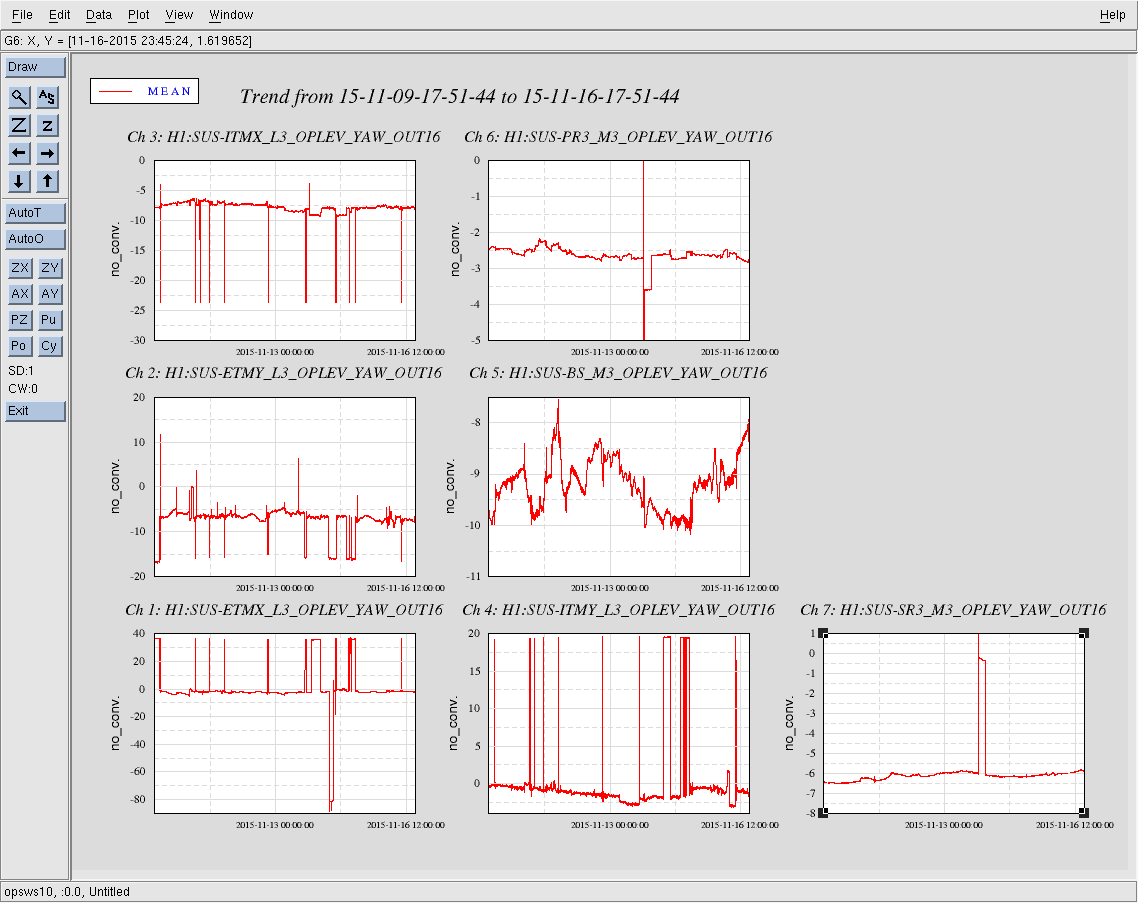
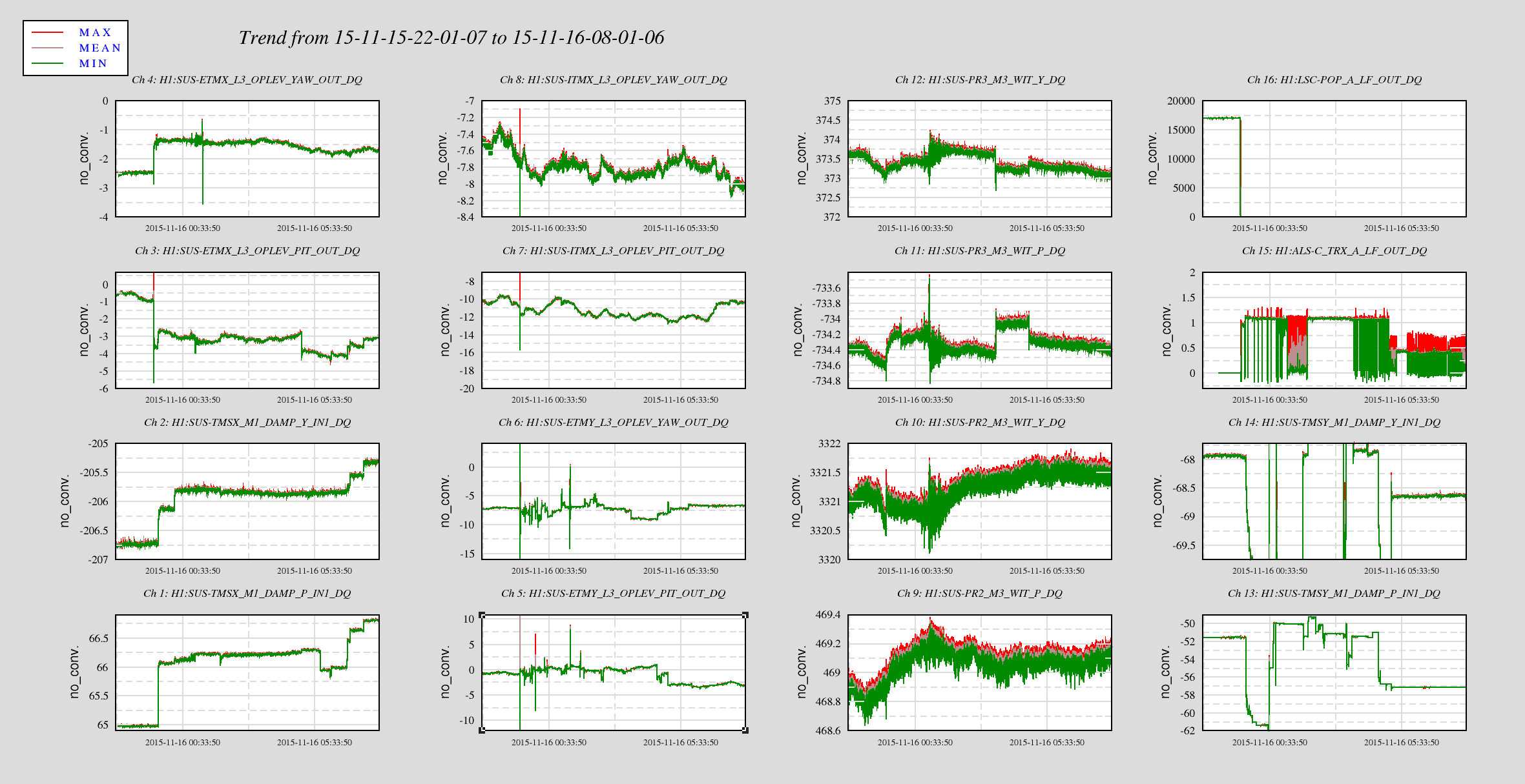
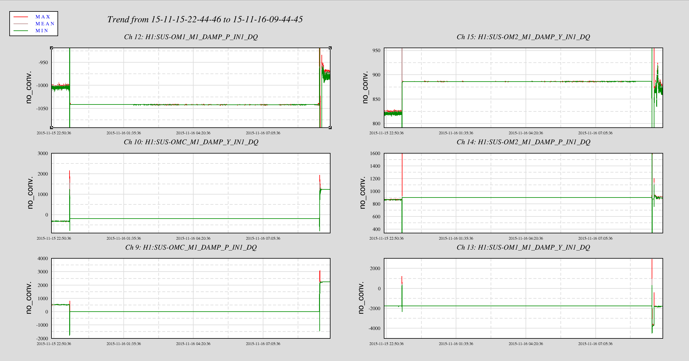
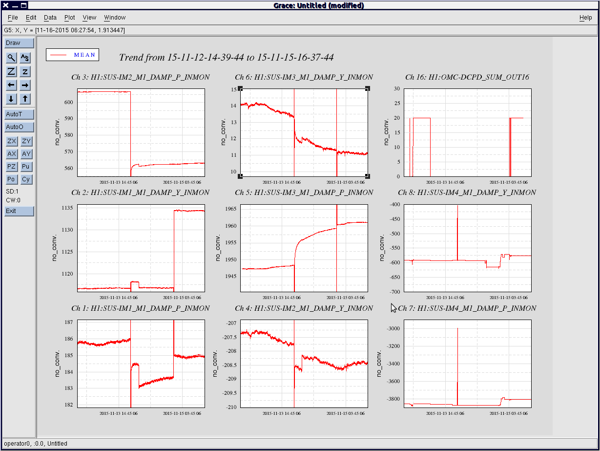
I've attached plot showing the IM alignment channels.
Armed with those channels, and the knowledge that the IM OSEM values are trustworthy, and the knowledge that under normal running conditions IM1-3 only drift 1-2urad in a day, checking and restoing IM alignemt after a shaking event (ISI trip, earthquake) should be a fairly quick process.
Attachments:
1) chart of IM1-3 changes 11/12 to 11/15 - the biggest steps are in blue
2) plot of IM1-4 alignment in pitch and yaw for the same time period
ON A COMPLETELY DIFFERENT NOTE:
Though the IM alignment shifts are unwanted, at this time they have been propigated to the full IFO, and the IFO is locked at around 80Mpc, which gives us an indication of the tollerance for alignment changes in the IMs.
This is not to say that all is the same in the IFO, because it is possible that some increase or decrease in noise is associated with IM change in alignment.
