Darkhan, Jenne, Stefan, Evan
Upon revisiting the shape of the DARM loop, we found that we had 4 dB of gain peaking from 10 Hz to 50 Hz.
That seems a bit too strong for our taste, so we took a look at the DARM suscomp filter that we've been using for the past few months. Aside from the low-frequency (<2 Hz) suspension resonance compensation and the high-frequency (>900 Hz) inversion rolloff, there is a single pole at 200 Hz.
This serves us well when locking DIFF, but in full, low-noise lock it costs us phase (not least because we also have the effect of the 350 Hz RSE pole).
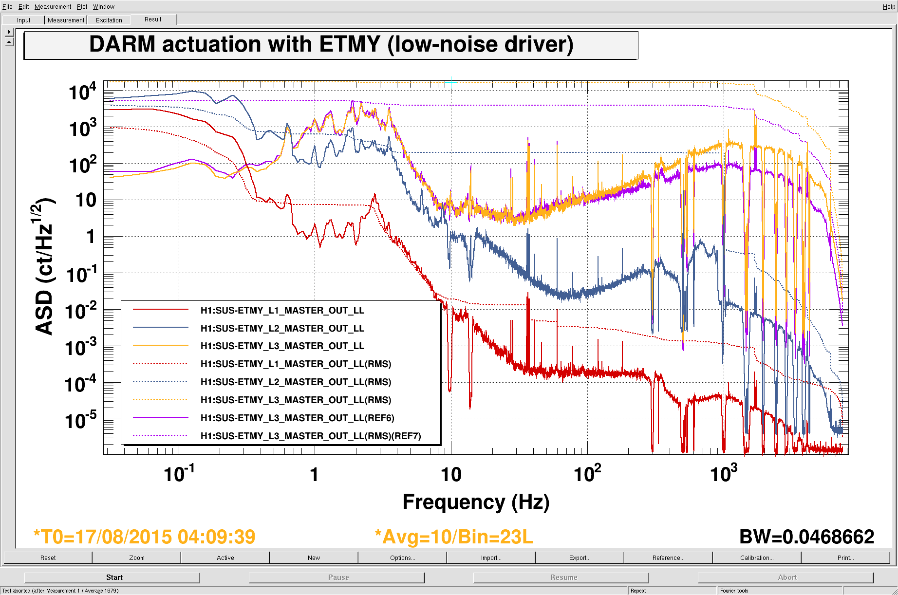
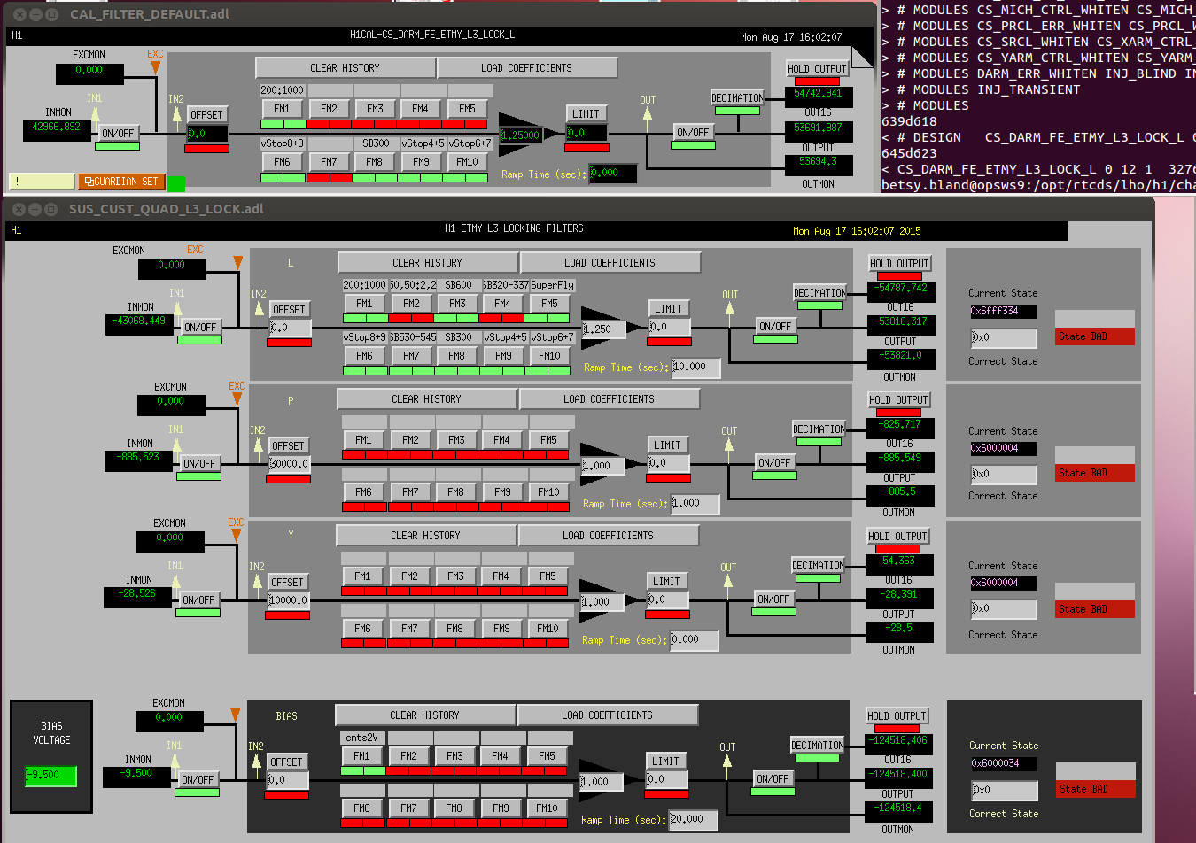
Anyway, there is now a filter installed in EY L3 lock with a zero at 200 Hz and a pole at 1000 Hz in order to push this pole up to higher frequency. This gives us a modest improvement in phase margin at the DARM ugf (34° to 46°). The DARM ugf is 40 Hz or so (more or less the same as before). The EY ESD has about 16000 ct rms, mostly accumulated around 1 kHz (magenta/orange in the attached spectra show the before/after).
[In the longer term, we should just roll p/z pair into the suscomp filter, so that it rises like f essentially from 1 Hz to 1 kHz. Then put a 200 Hz pole / 1000 Hz zero pair in EX L3 lock, so as not to disturb the DIFF loop shape. However, I've put what we have so far into the guardian and it works fine.]
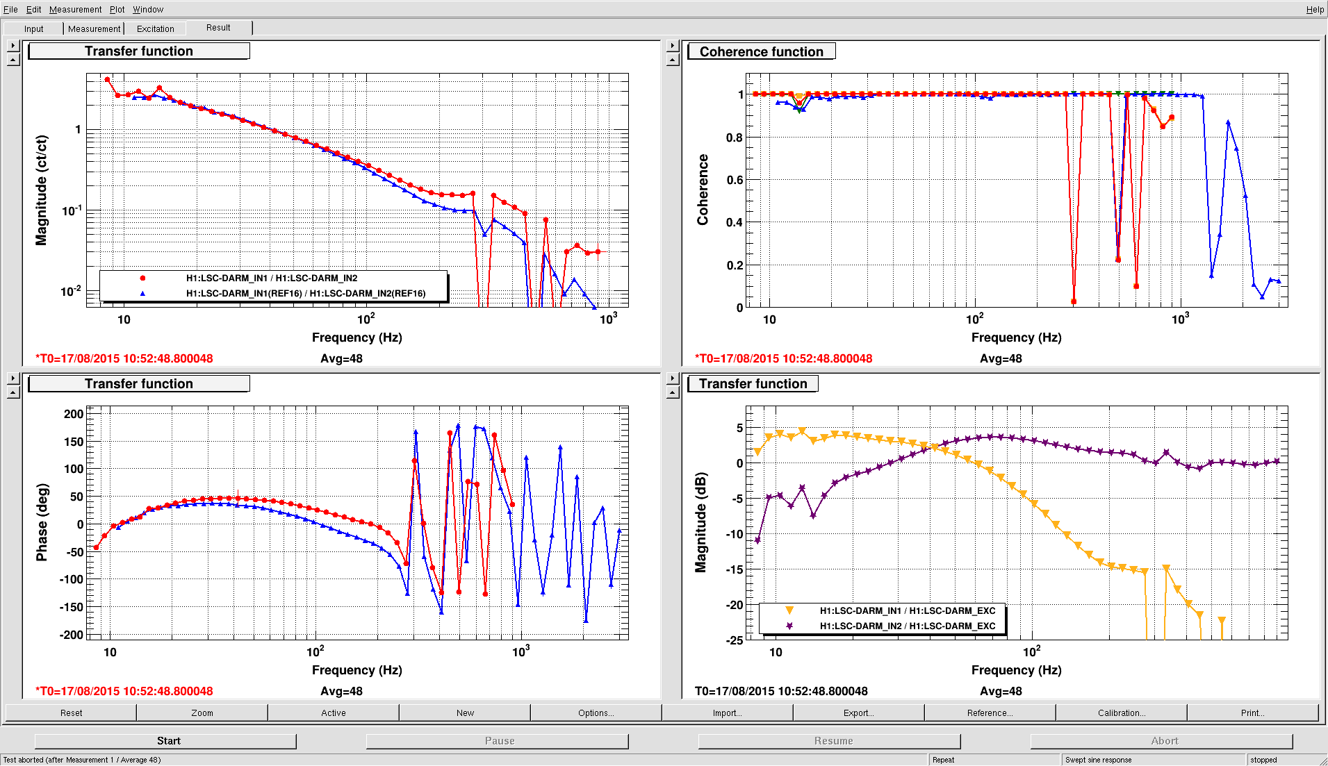
Darkhan and I retuned the DARM OLTF template in order to not saturate with this new loop shape. The attachment shows the before (blue) and after (red), along with the closed-loop gain and loop suppression. There's still moderate gain peaking below 20 Hz.