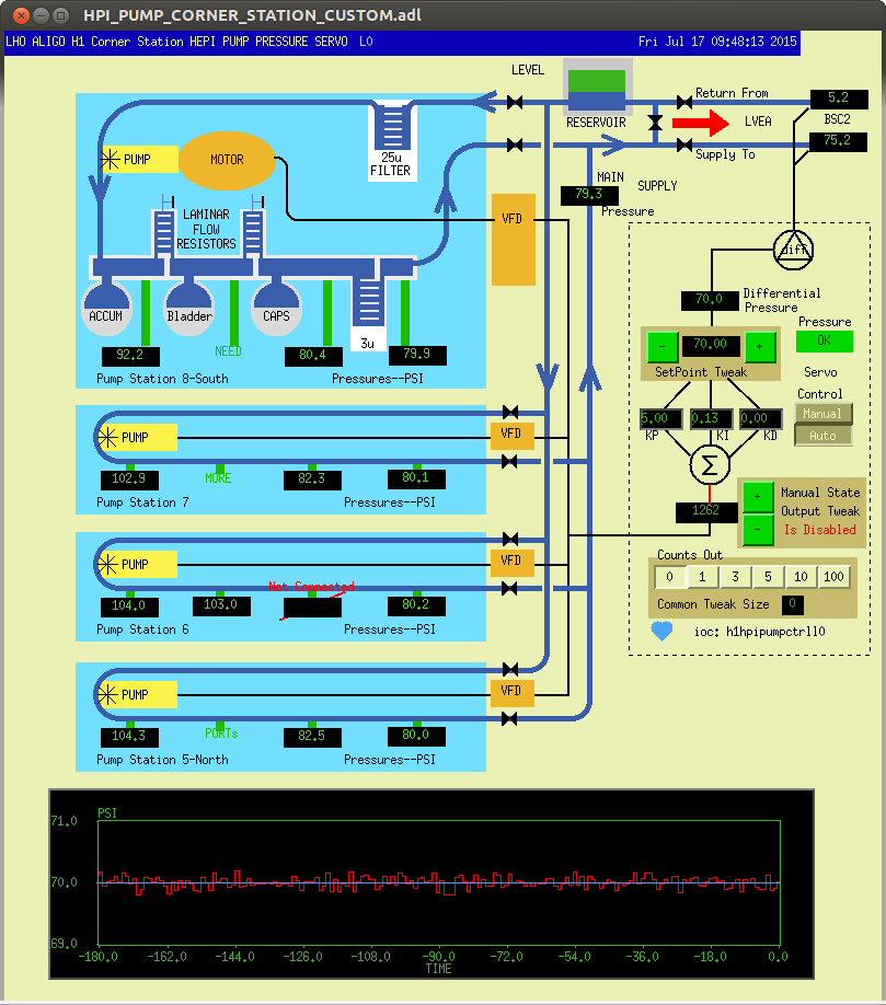
On Tuesday all the HEPI Pumps were spun down to check system Accumulators' pressures. Upon bringing them back into service, I noticed CS PS#8 sounded funny. I had also greased this and another motor and suspect maybe this greasing has packed the motor too tightly. See the first attachment of the Pump Controller Medm to follow along if you wish.
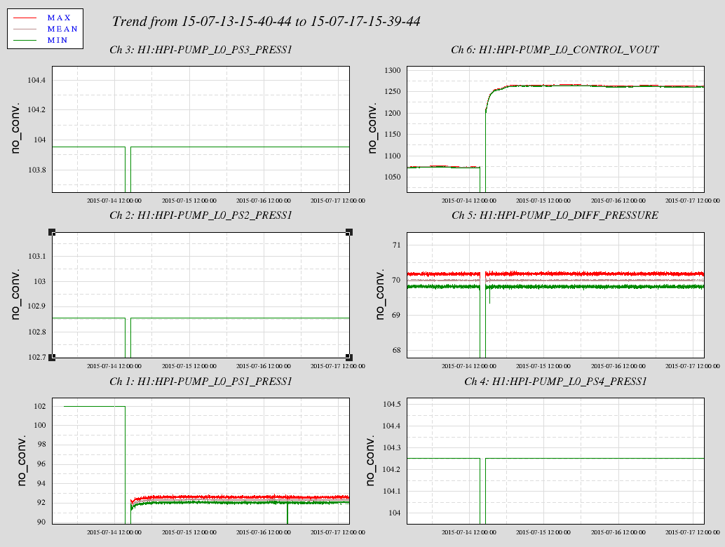
See the second attachment showing the last four days spanning the down time on Tuesday. Notice how after the pumps come back on, PS1_PRESS1 (epics channel name) is lower by 10psi and is also much noisier. PRESS1 is the sensor just after the pump before resistors and filters.
I was a little baffled at first seeing that the other Pump Stations PRESS1 was exactly the same but it now makes sense. The system servos on the differential pressure across the actuators at BSC2 and that is a direct function of the total output of the four pump stations. Working back upstream to the Pump, the resistances giving the pressure drops across the 3u filter and the two laminar flow resistors have not changed hence the Pressure out of the other three pumps have not changed. However, now that Pump #8 is not putting out the same as before, the other pumps must spin faster to achieve our total desired output. Hence the 20% increase in motor speed shown on the VOUT channel.
I propose I take this PS offline on Tuesday; it may stay offline for a week or I may get it back in one day. I can do this with out having to deisolate any HEPI platforms although there may be a minor pressure glitch when I valve out this pump station as the motor stops. Still this pressure glitch may be seen on the platforms, see the effect on the BS if you care here when I greased motors May 2014. The glitches from this can be seen as 'deep' as the SUS ISI Witness channels although I don't know if these are actually strong. Bottom line, this certainly should not be done during any measurements.
And I will renumber the physical pump station and medm to stop the madness of different numbers.