Daniel H, Matt H (and help at various times from Hugh, Greg G, Kiwamu, Sheila, others)
Todays events
So a quick summary of todays work as too tired to write a detailed one sorry.
The in-vacuum cables were connected back onto the OMC and we confirmed we had signals etc. Also had a go at roughly moving the beam diverter to the position Keita/Dan hoped they could sqeeze it so as to not to have to move optics/SEI balance masses. We also had a look at trying to strain relieve the cables on the OMC that touch the OMC black glass shroud. But it looks like these are very touchy and altering these alter the balance.
Decided to analyse more with a laser beam.
Had troubles locking the mode cleaner. Apparently it was chased down to some whitening problem (something that last appeared around May 2014 I think I overheard). Once input mode cleaner locked and Dan had it set in a single bounce configuration, The "M8" mirror (near the tiptilt and OMC shroud) was replaced (as was the additional black glass beam dump we had to remove for the OMC shroud install). The septum viewport protector was removed. Dan was estatic (okay maybe he wasnt estatic but he was happy) that immediately saw signals. Looking at the OMC glass shroud and the beams though it looks like they go through very close to the center. Well done to Eddie Sanchez and the SYS team for all their hard work with the design to make sure they did.
We played more with the cables but in the end I decided to pull the trigger on removing the two upper black glass plates that r the cables that go to the glass bench are touching (it pained me to do so after all the hard work putting it in). Playing with the cables more we were able to get it to a point that Dan was "happy" with....(he would like it better if could but we decided we were at the point that perfection was the evil of good enough).
Note: we have it so that no offsets on the OMC like used to have
Then checked beam aligment out of OMC. As M8 didnt go back exaclty in the same spot, some of the optics had to be tweaked to re-establish the alignment. Also had to move a beam splitter as part of the beam diverter move. We chacked that both beam diverters still work in air. They did.
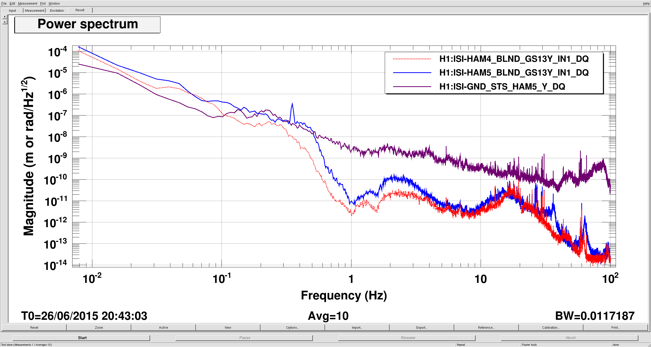
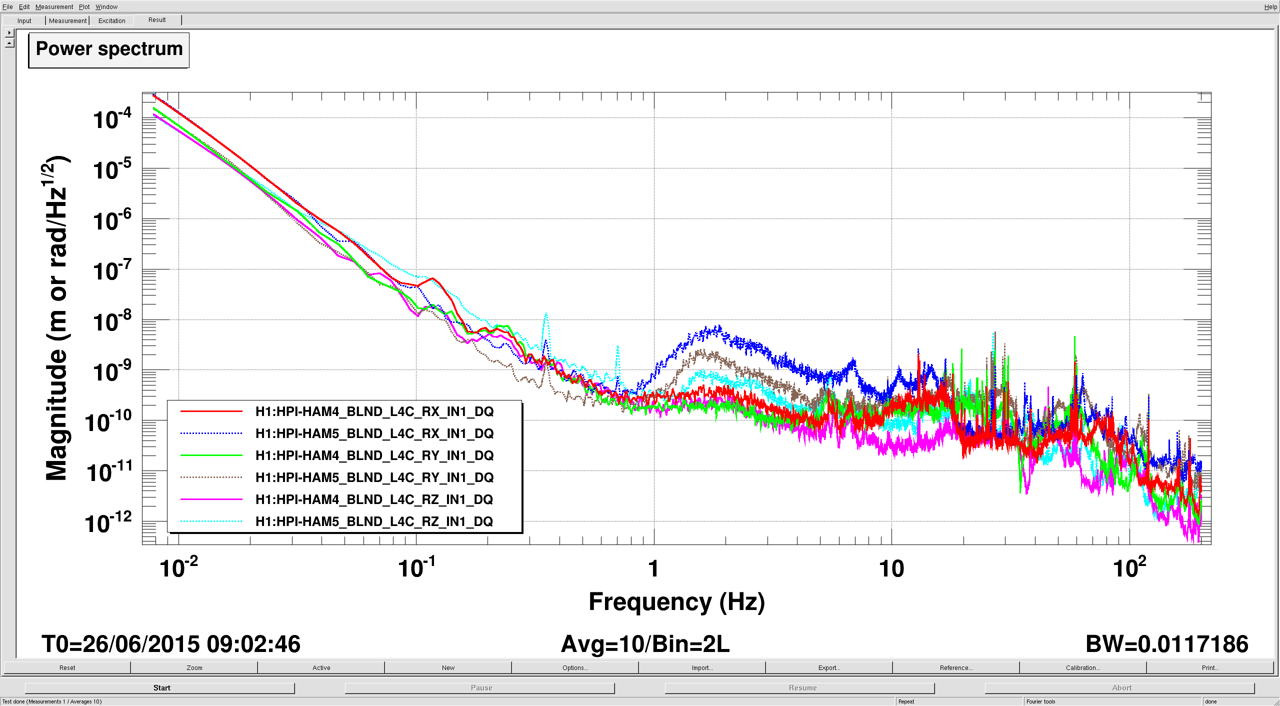
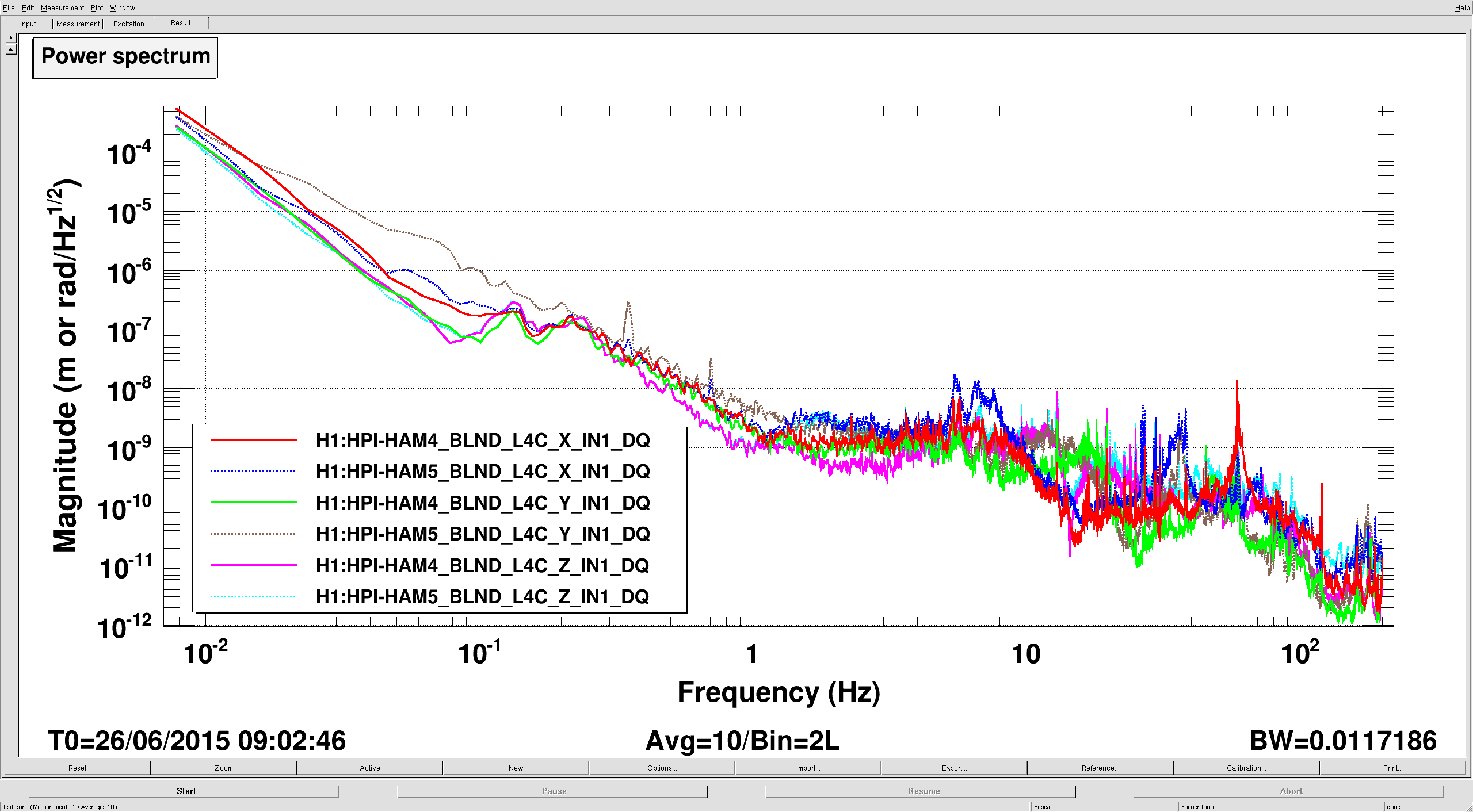
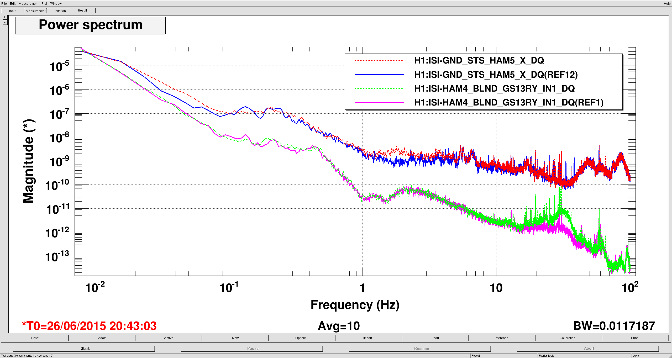
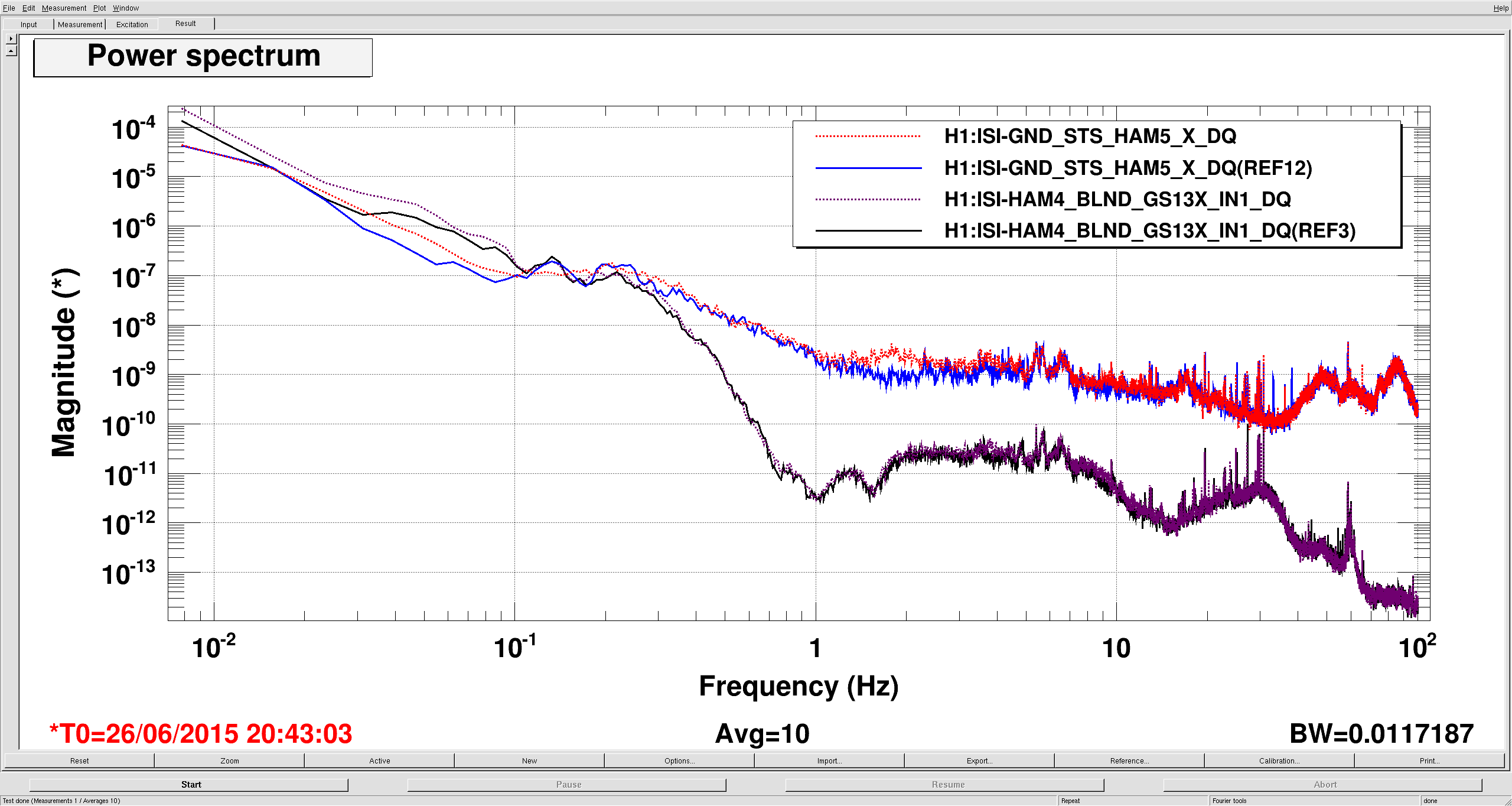
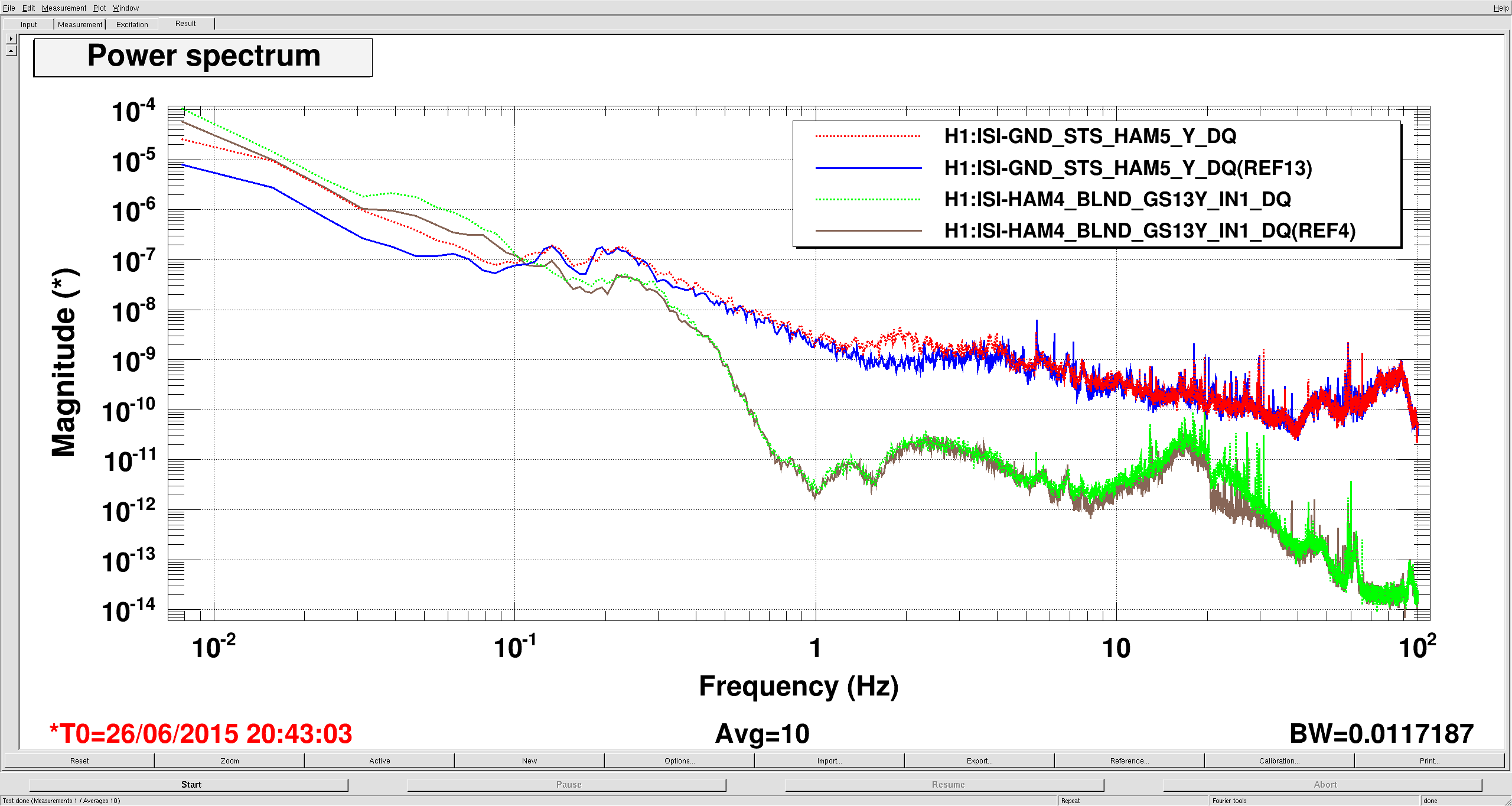
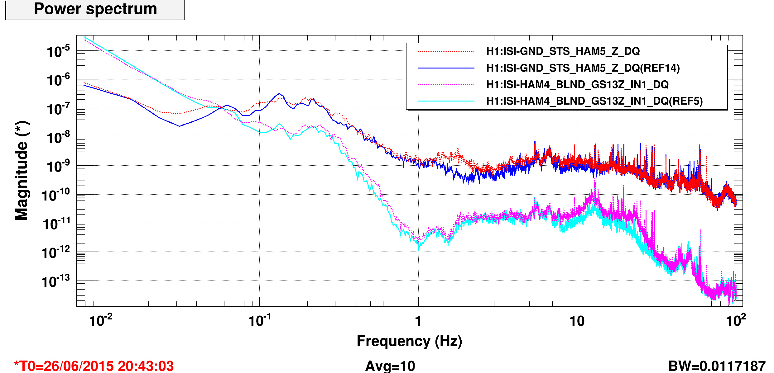
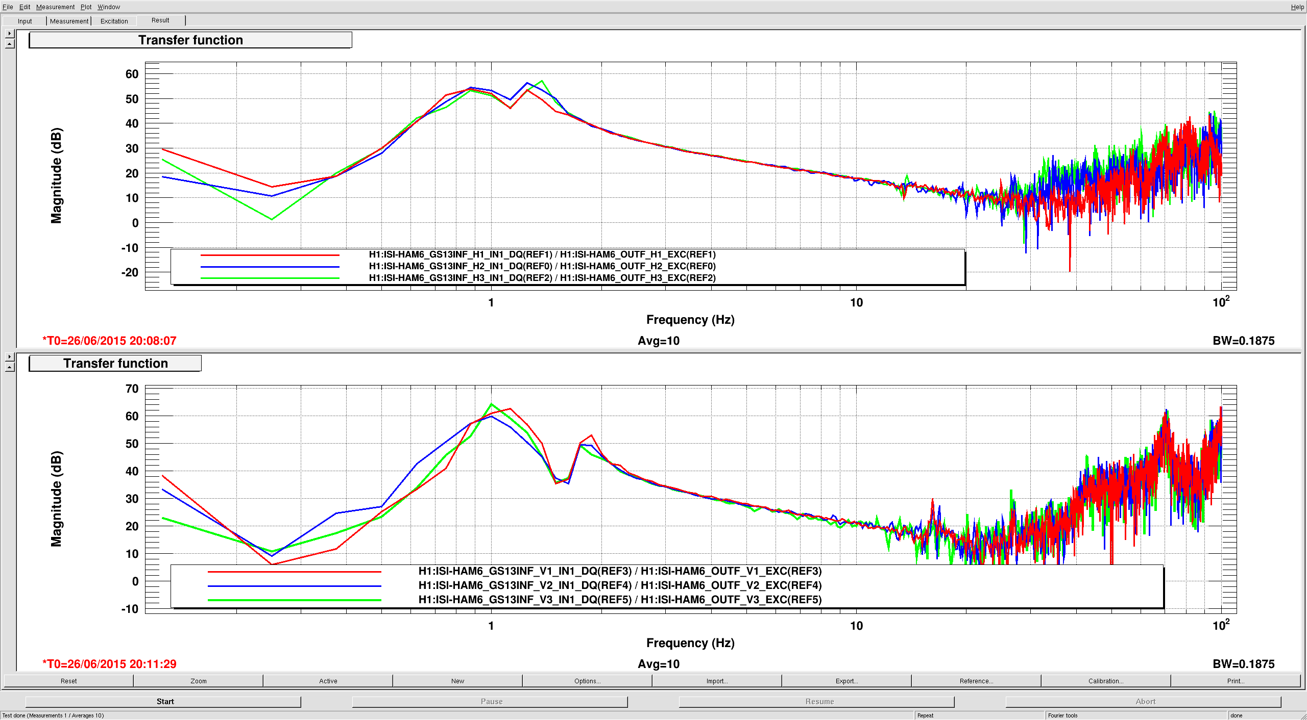
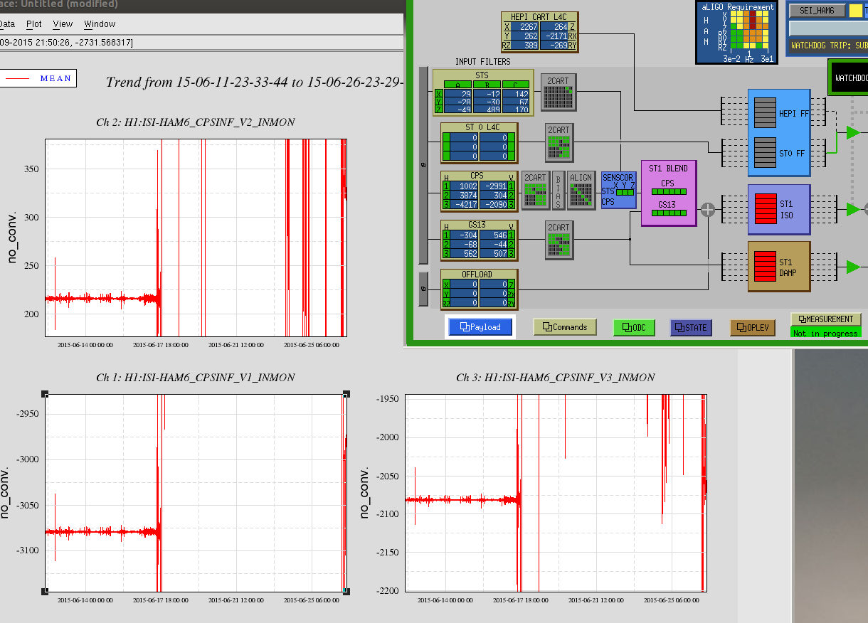
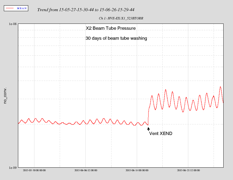
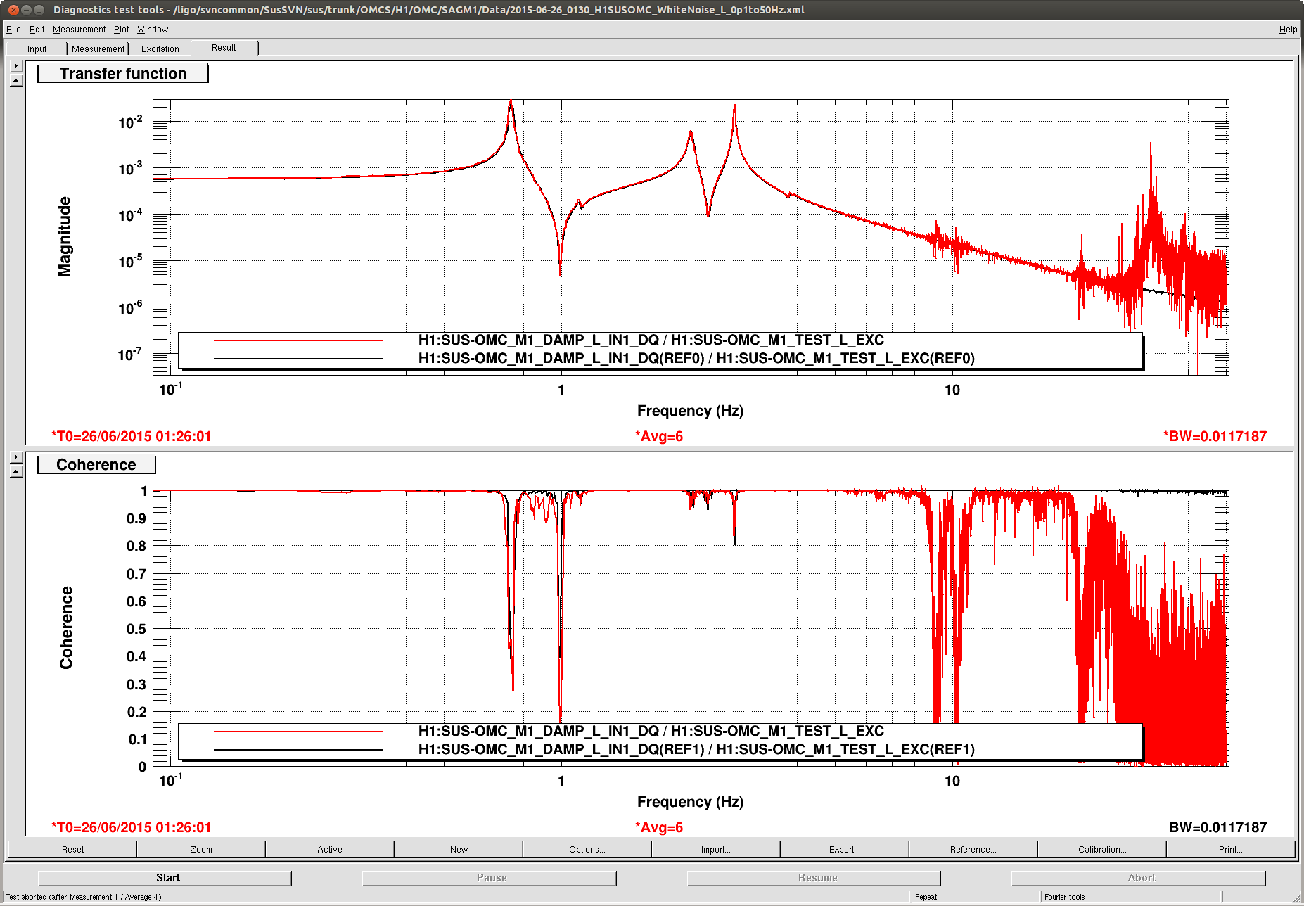
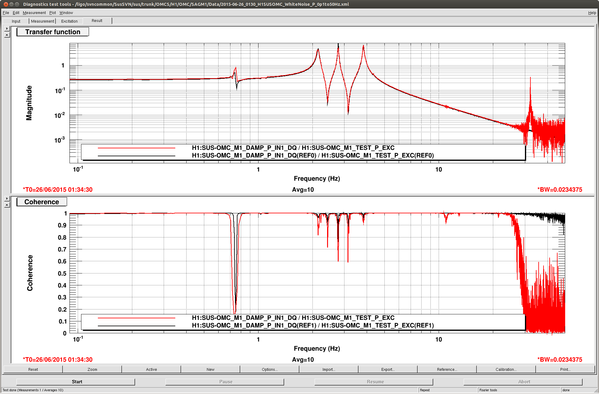
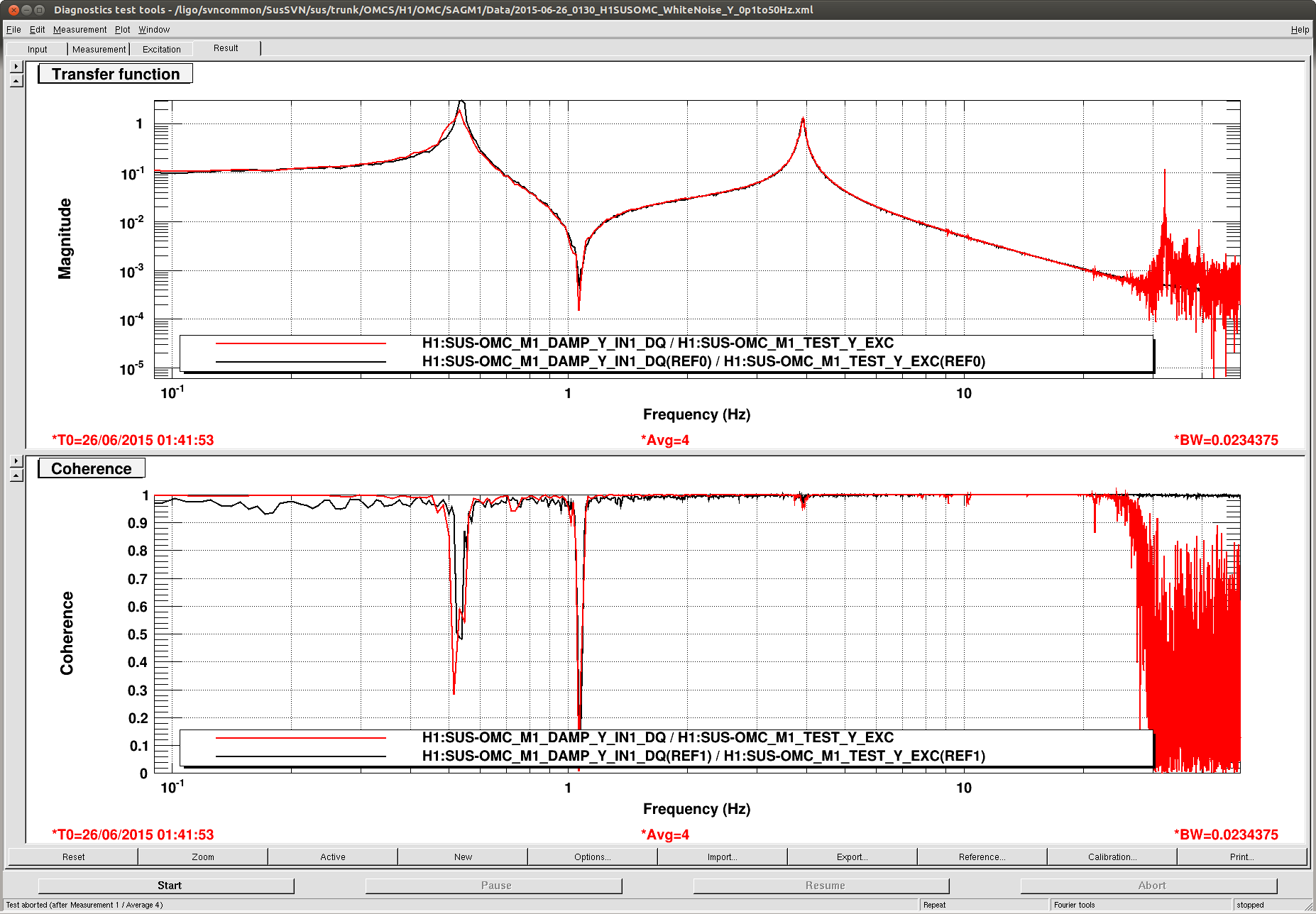
Also turned down purge air and did some TF's and they all passed (see attached).
Below is Dans much more succint summary......
Beam diverter was moved succesfully
90-10 BS was moved upstream of the second OMCR pico mirror; power on the QPDs has not changed (when the diverter is open)
Beam dump for 90-10 splitter was moved next to OMC SUS, should be out of the way
Alignment of OMCR path is good
Tested both beam diverters
Alignment into / out of OMC is excellent
Flashed OMC and saw the OMC TRANS beam out of the vacuum
OMC SUS TFs are good!
Purge air is on and OMC PZT HV is off.
Going forward tomorrow and still trying to get two bit of black glass back in
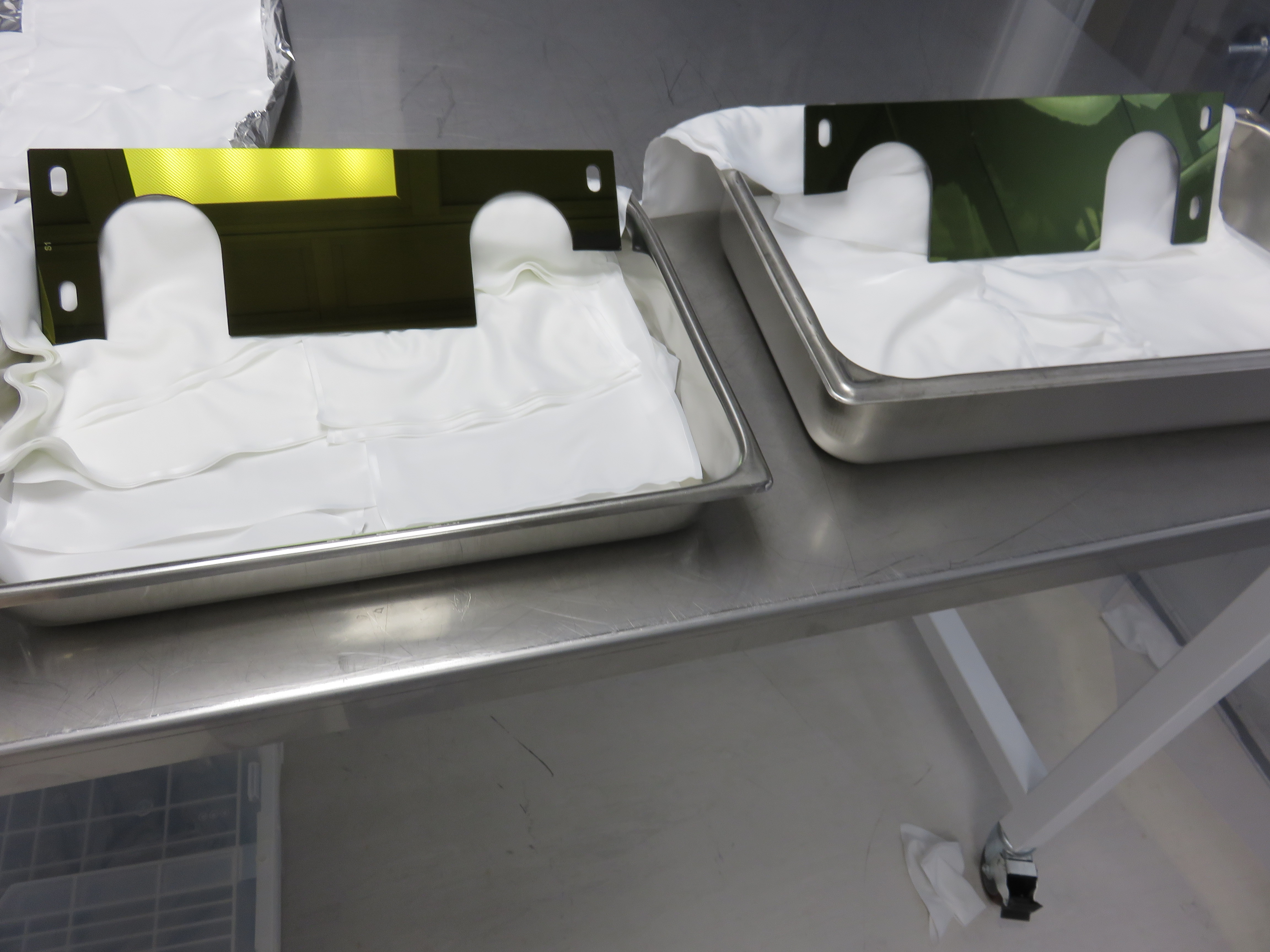
However not yet ready to hand over to Hugh for balancing. We are still actively investigating at how we can try to get both plates back in. After talking to Calum tonight he wants me to try putting at least one of the plates back in and taking some measurements to see how we might be able to modify the plates (ie maybe score and snap a bit off.......)
Also we should take TF's of tip tilts at some stage (after doors are on probably though).
Oh particle counts were basically all 0 in all locations (if not zero then had a reading of 10). Sorry am usually better at recording these details.
Pics:
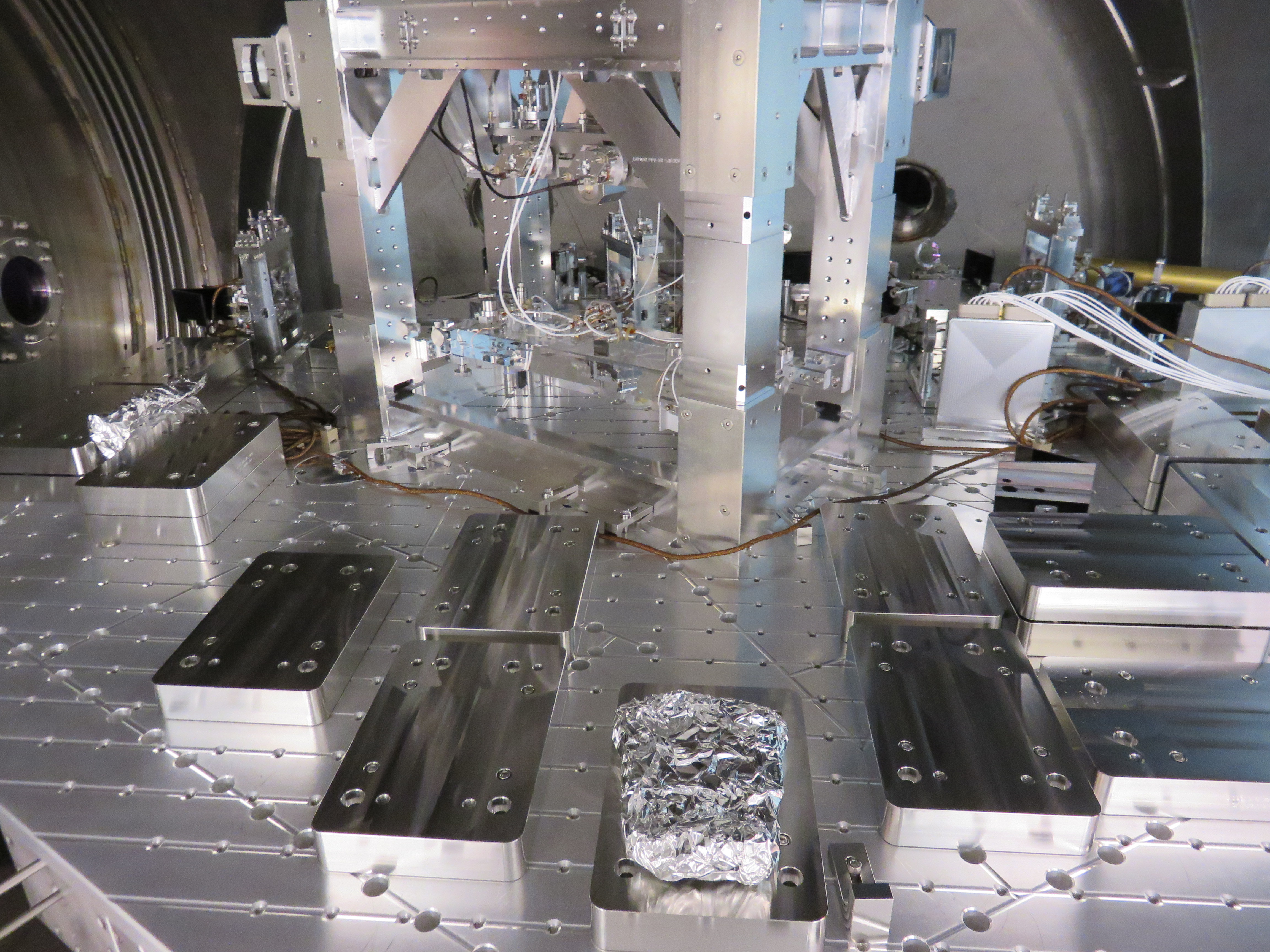
2403...before pic of the OMC before shroud work started
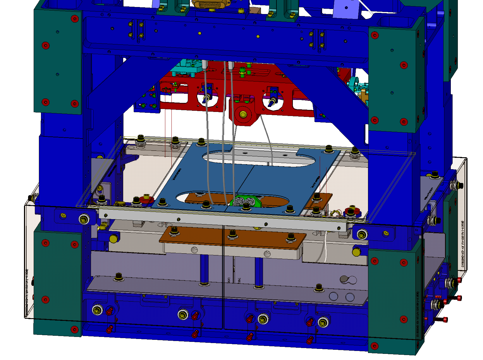
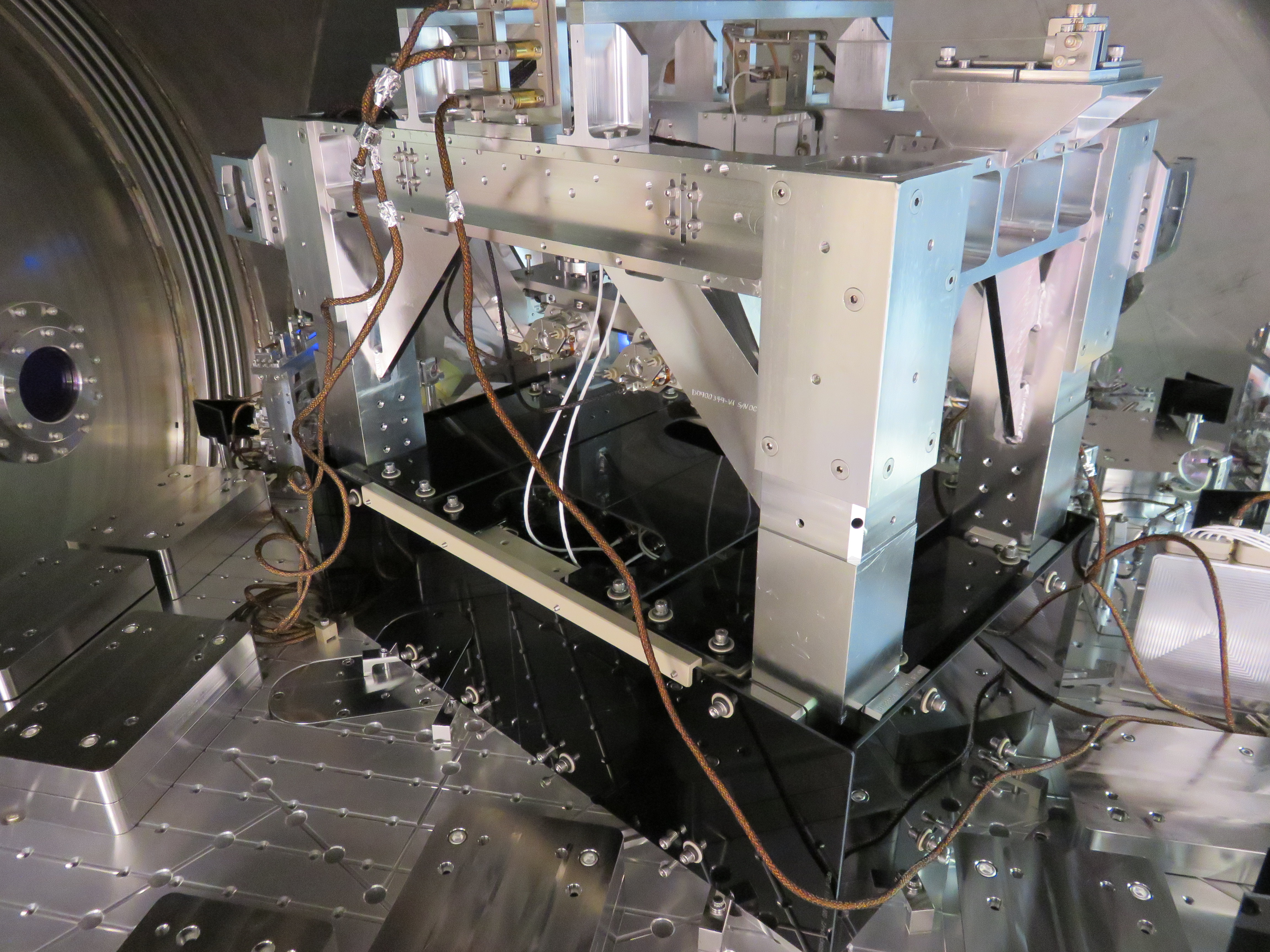
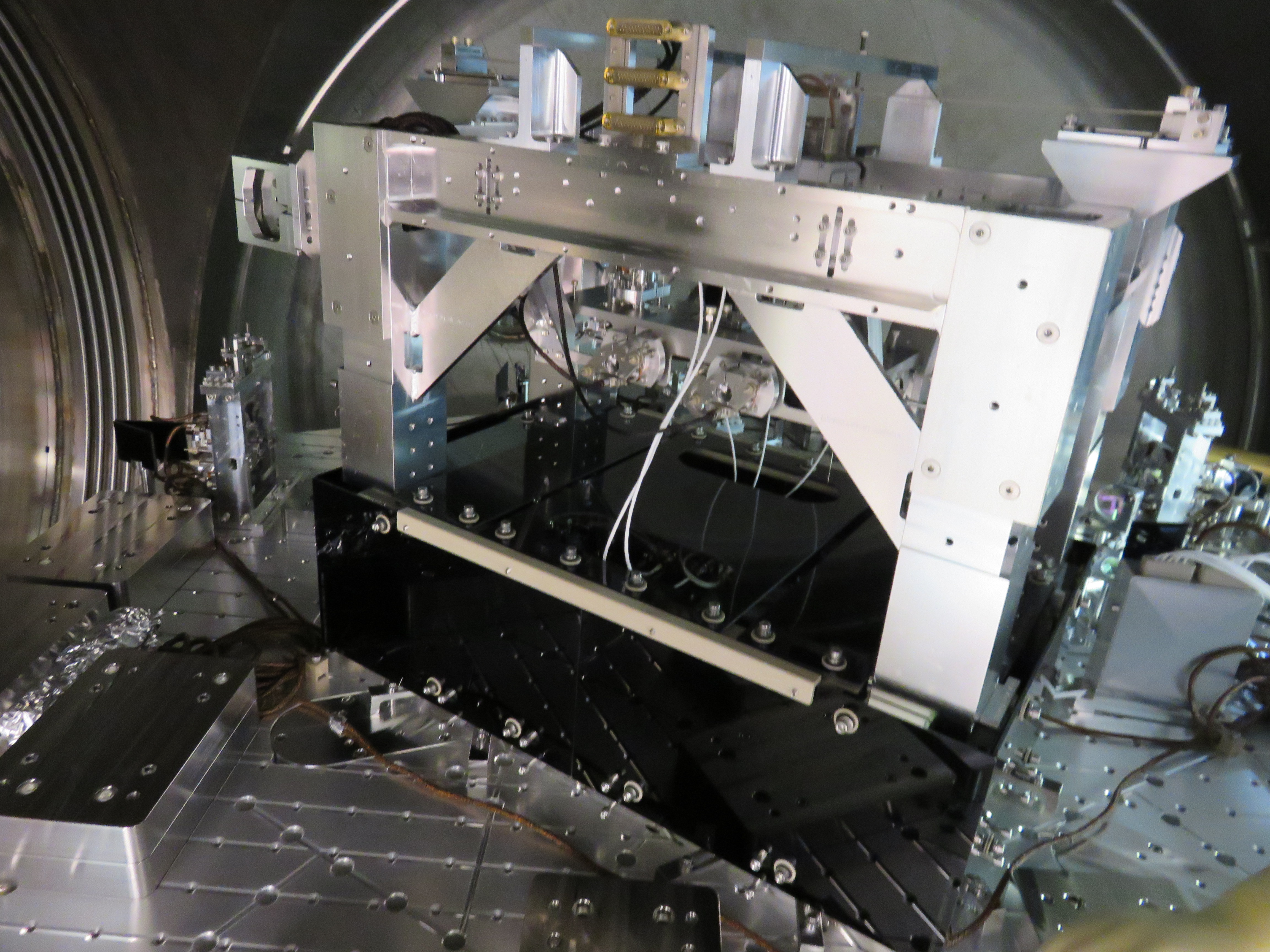
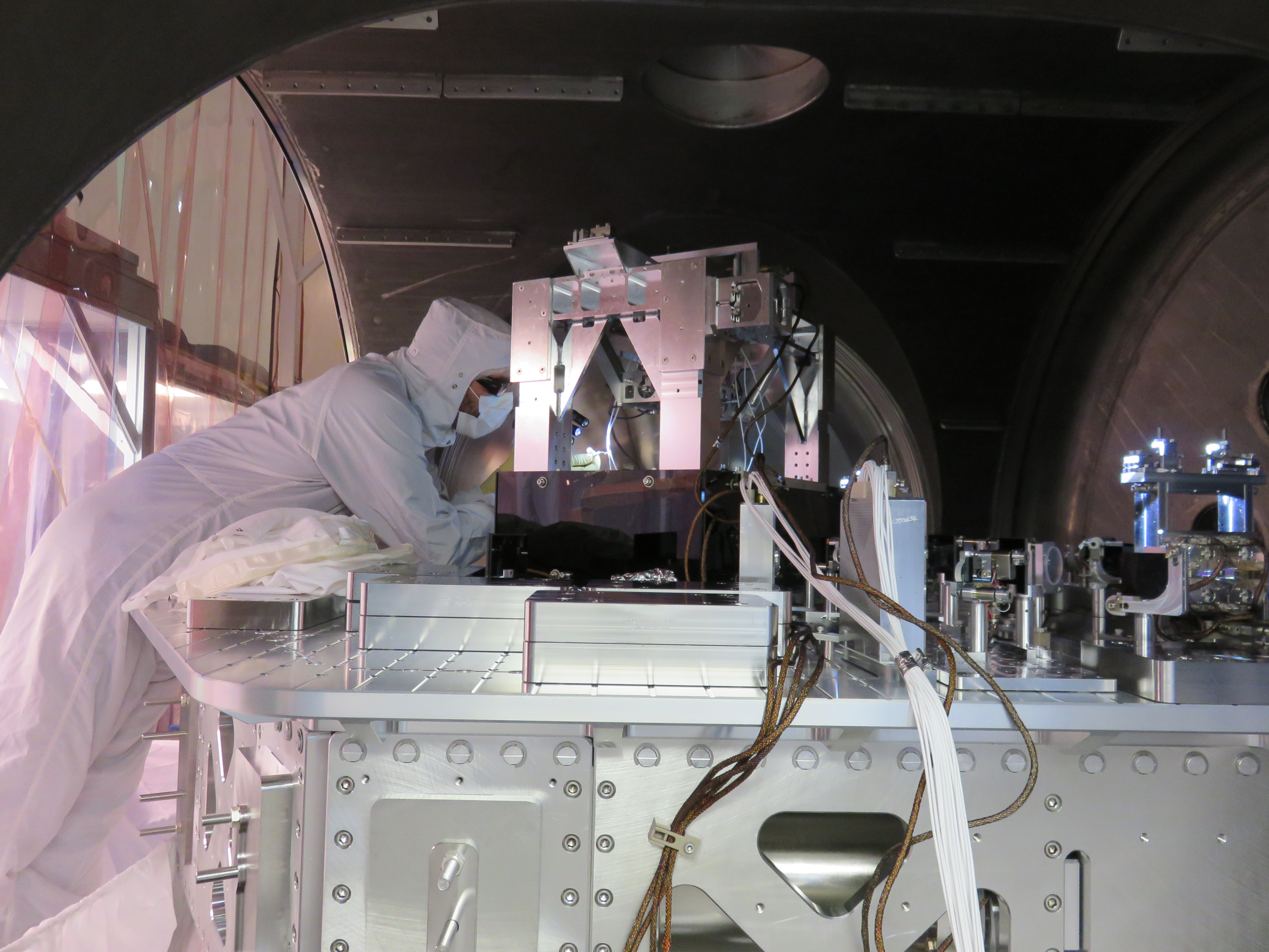
2426...OMC black glass shroud installed
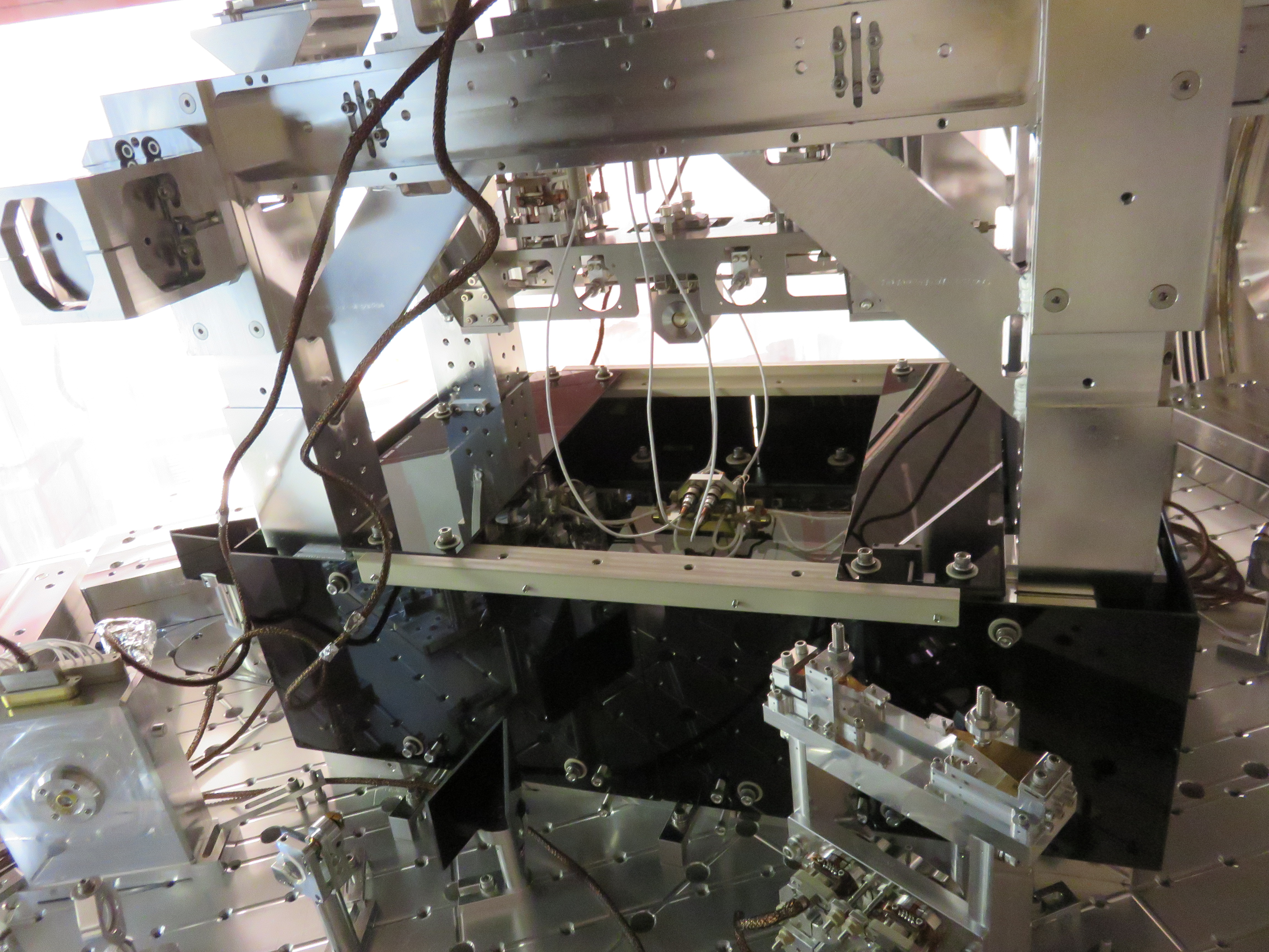
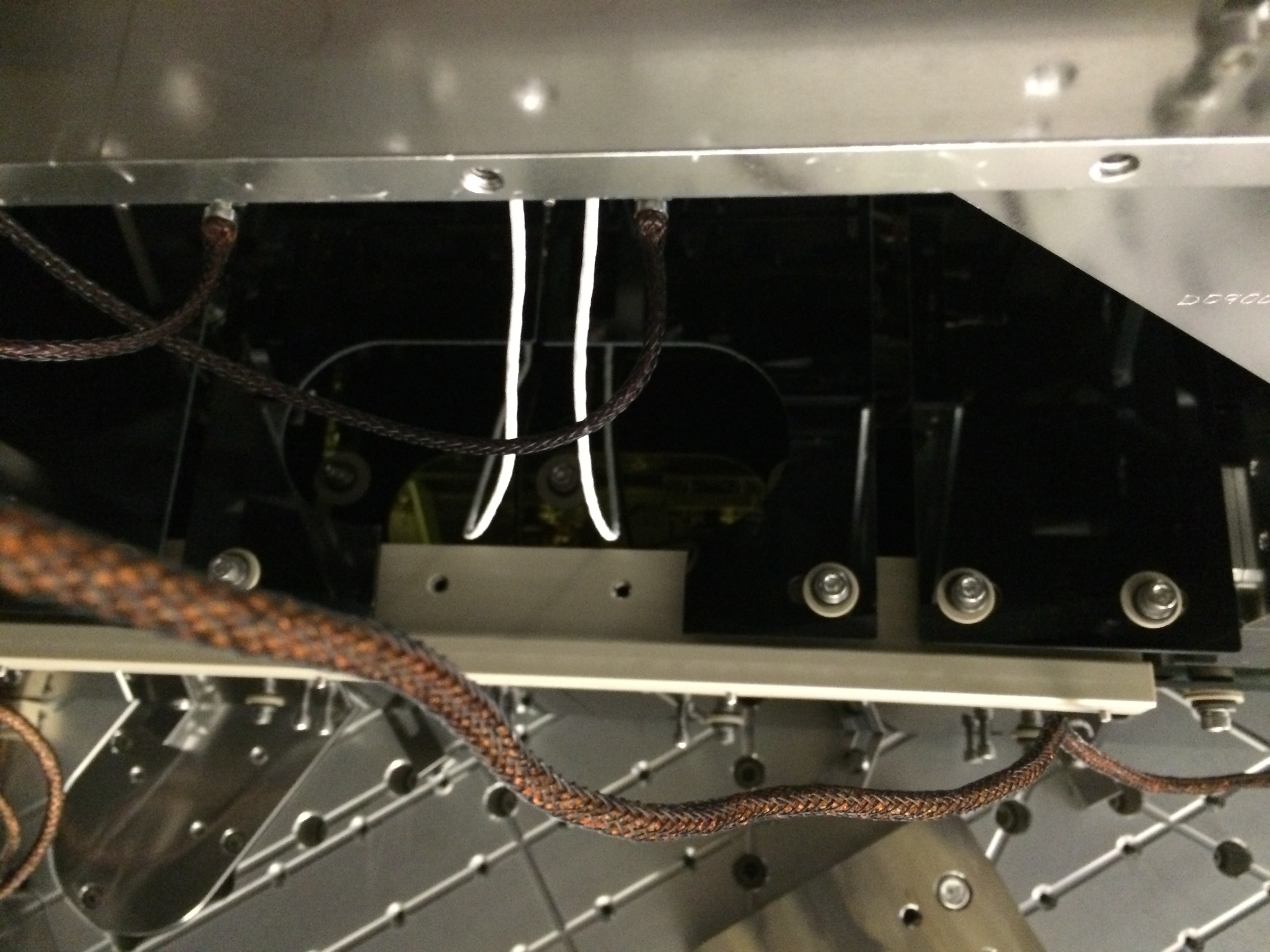
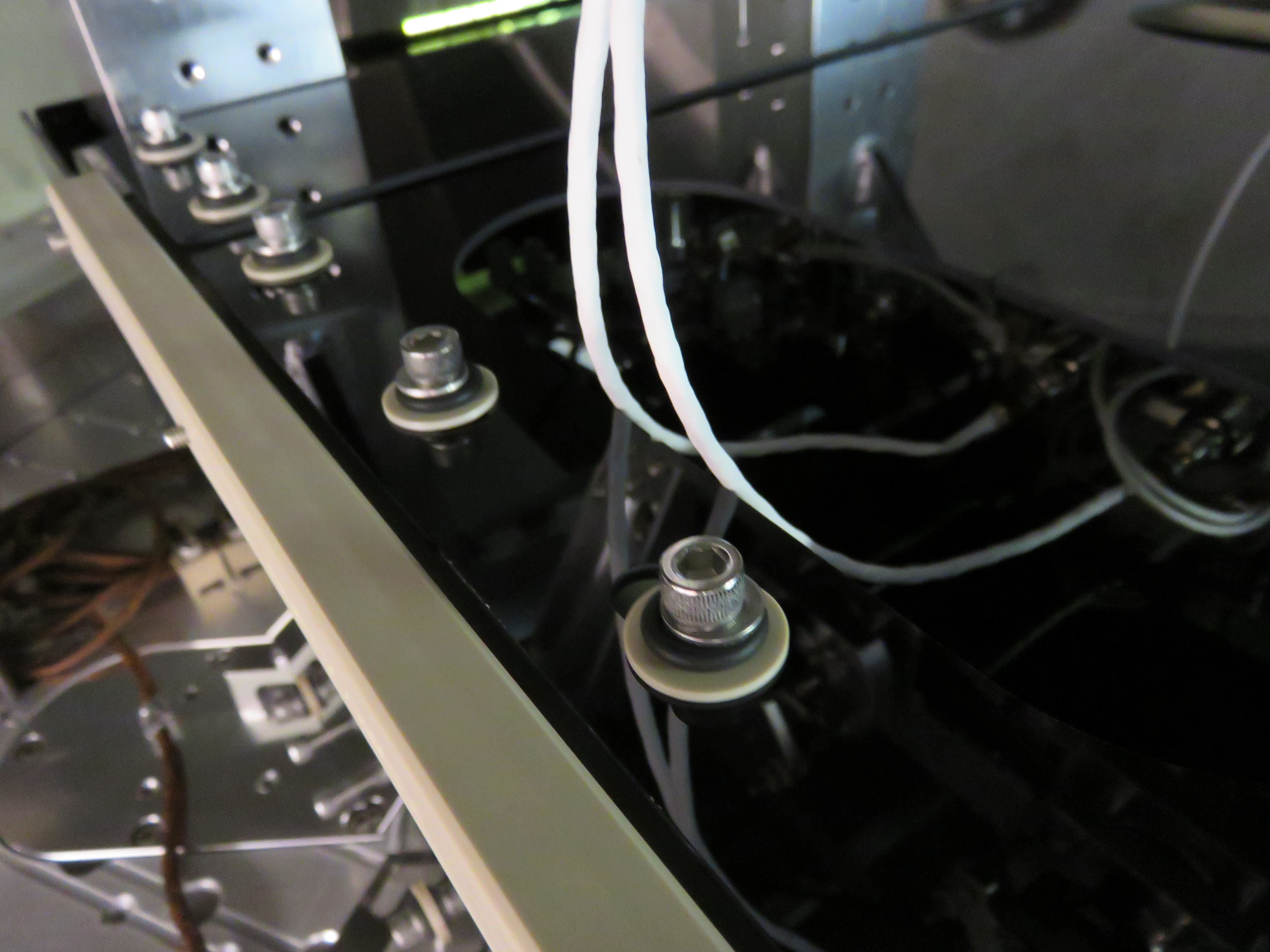
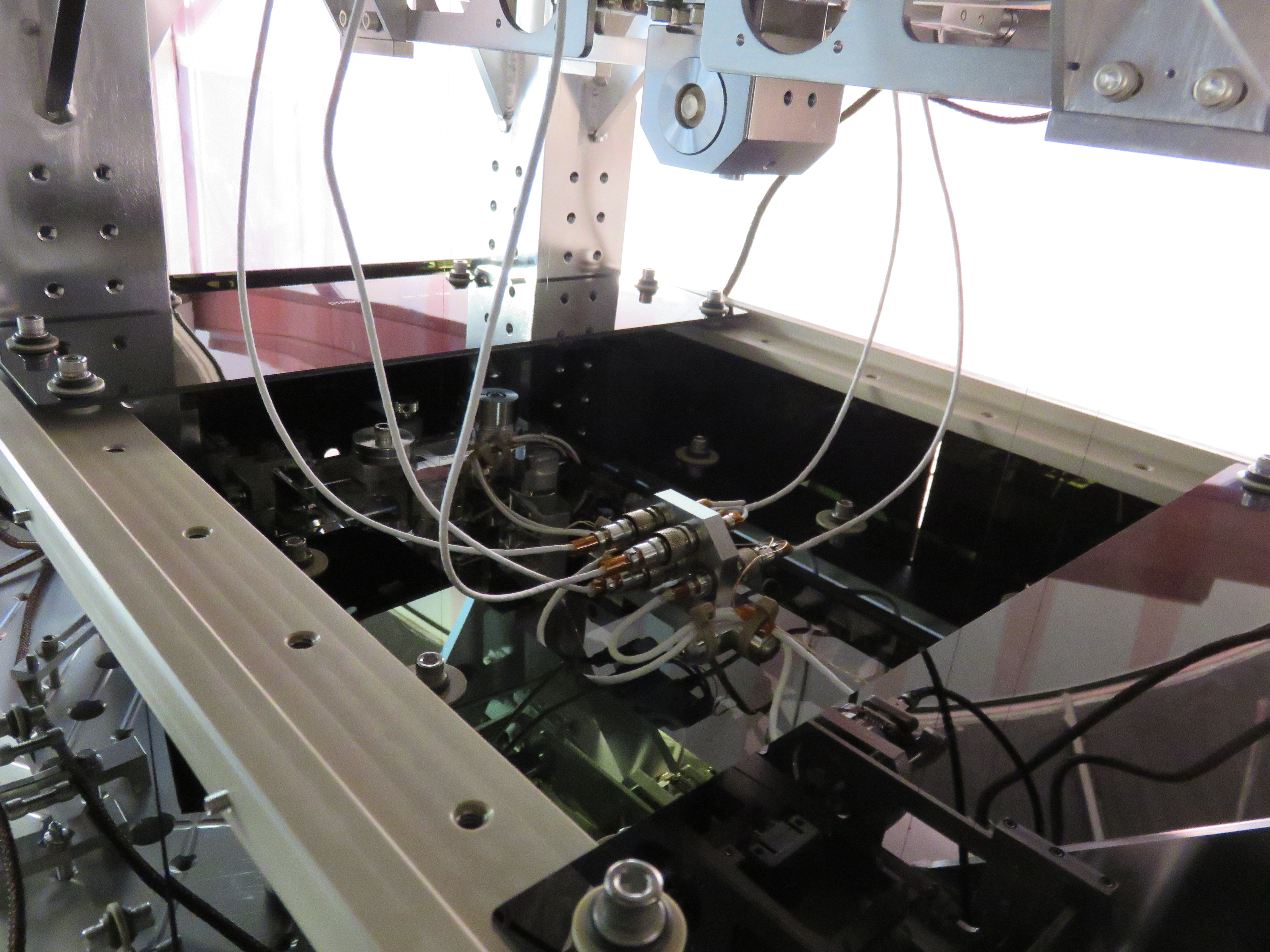
2424..the two cables on the OMC that interfere with the OMC black glass
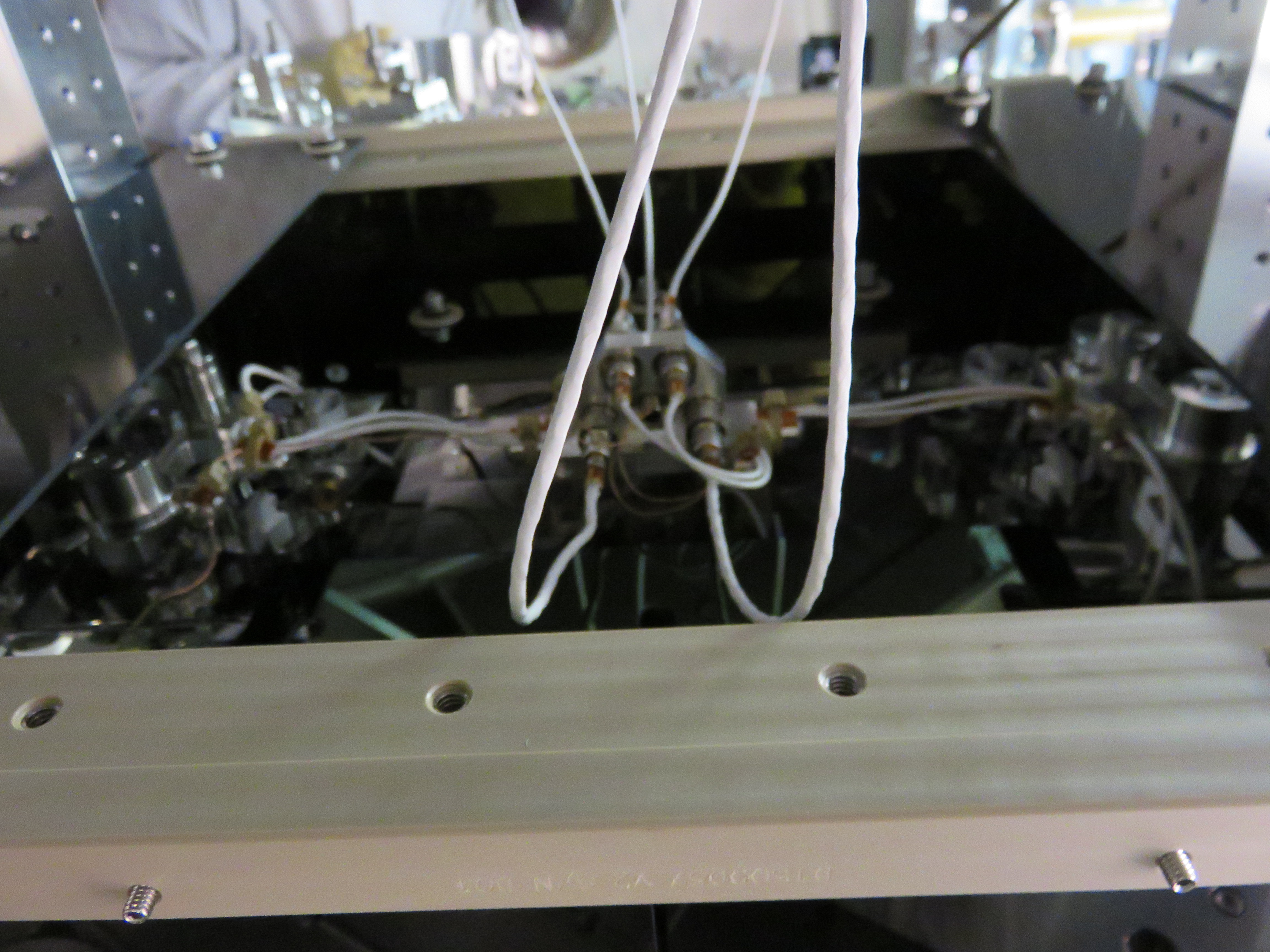
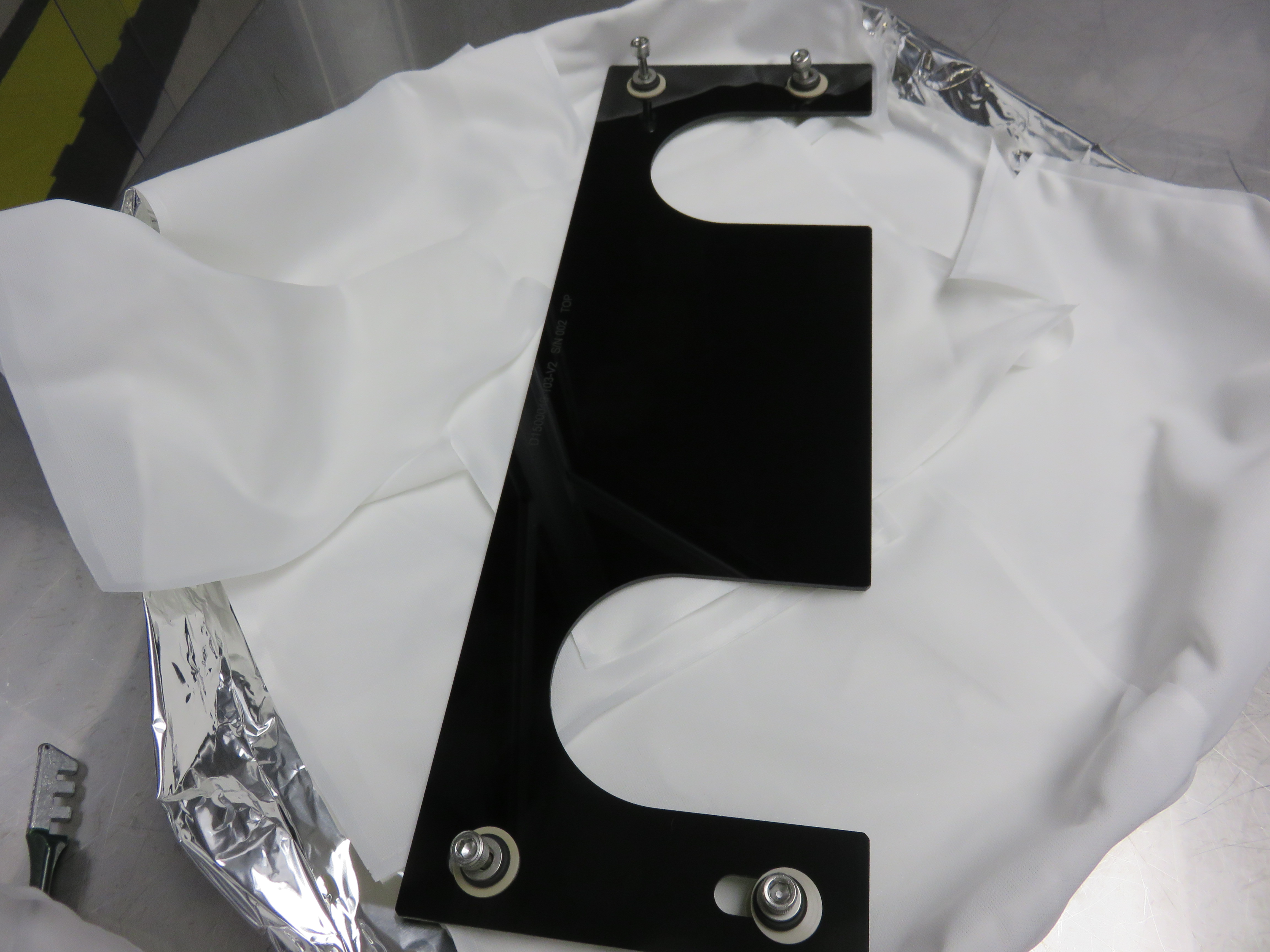
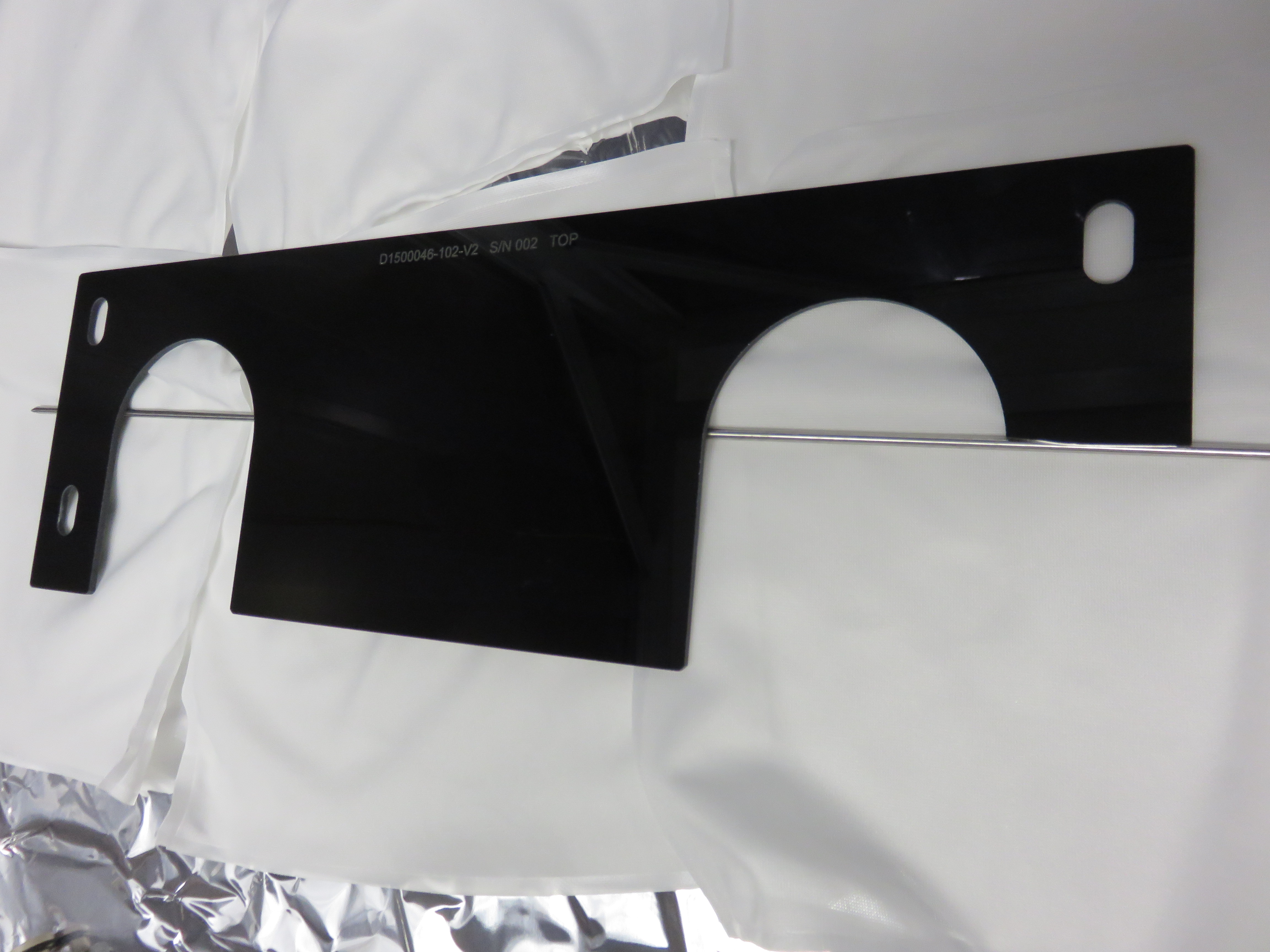
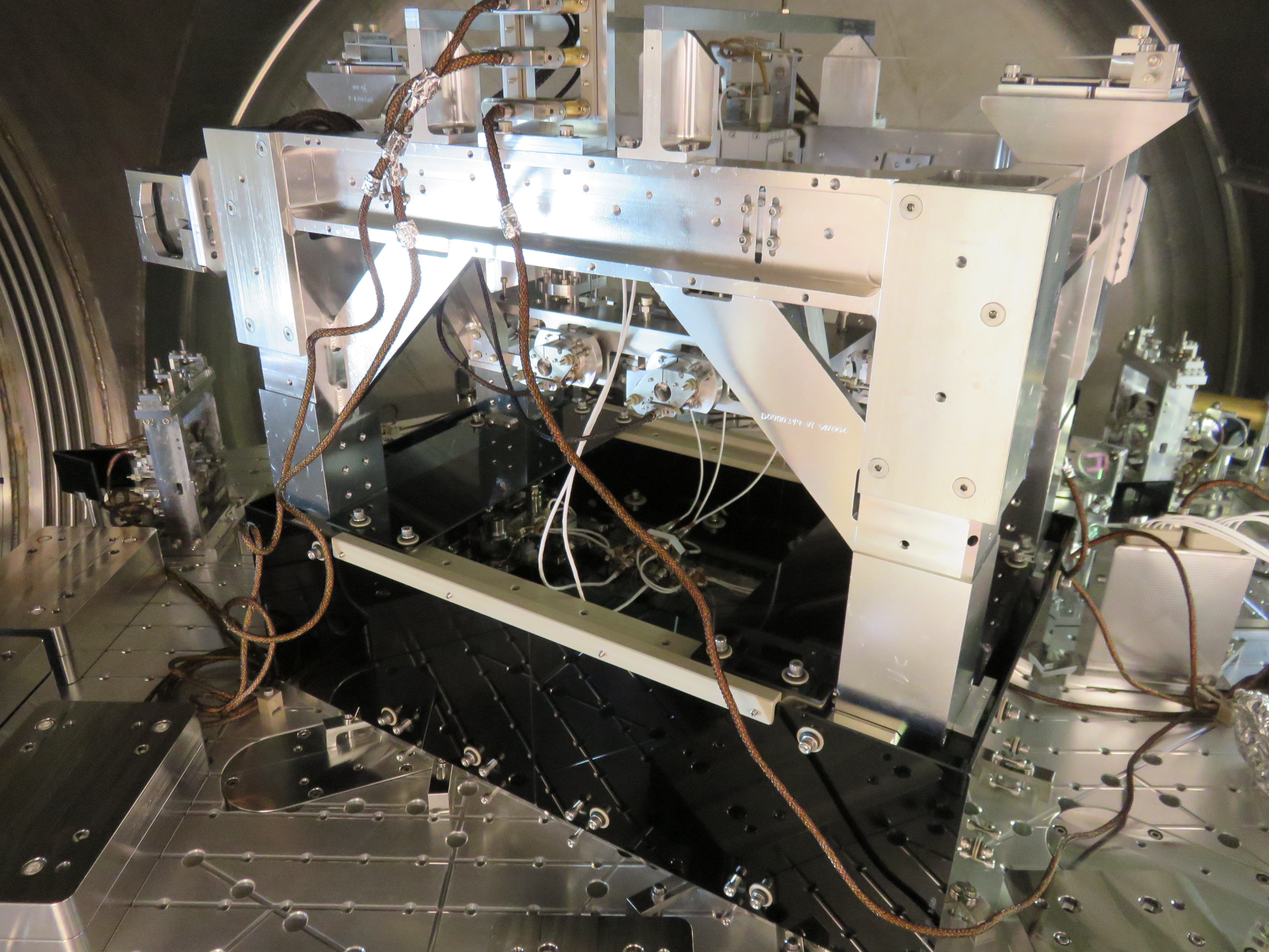
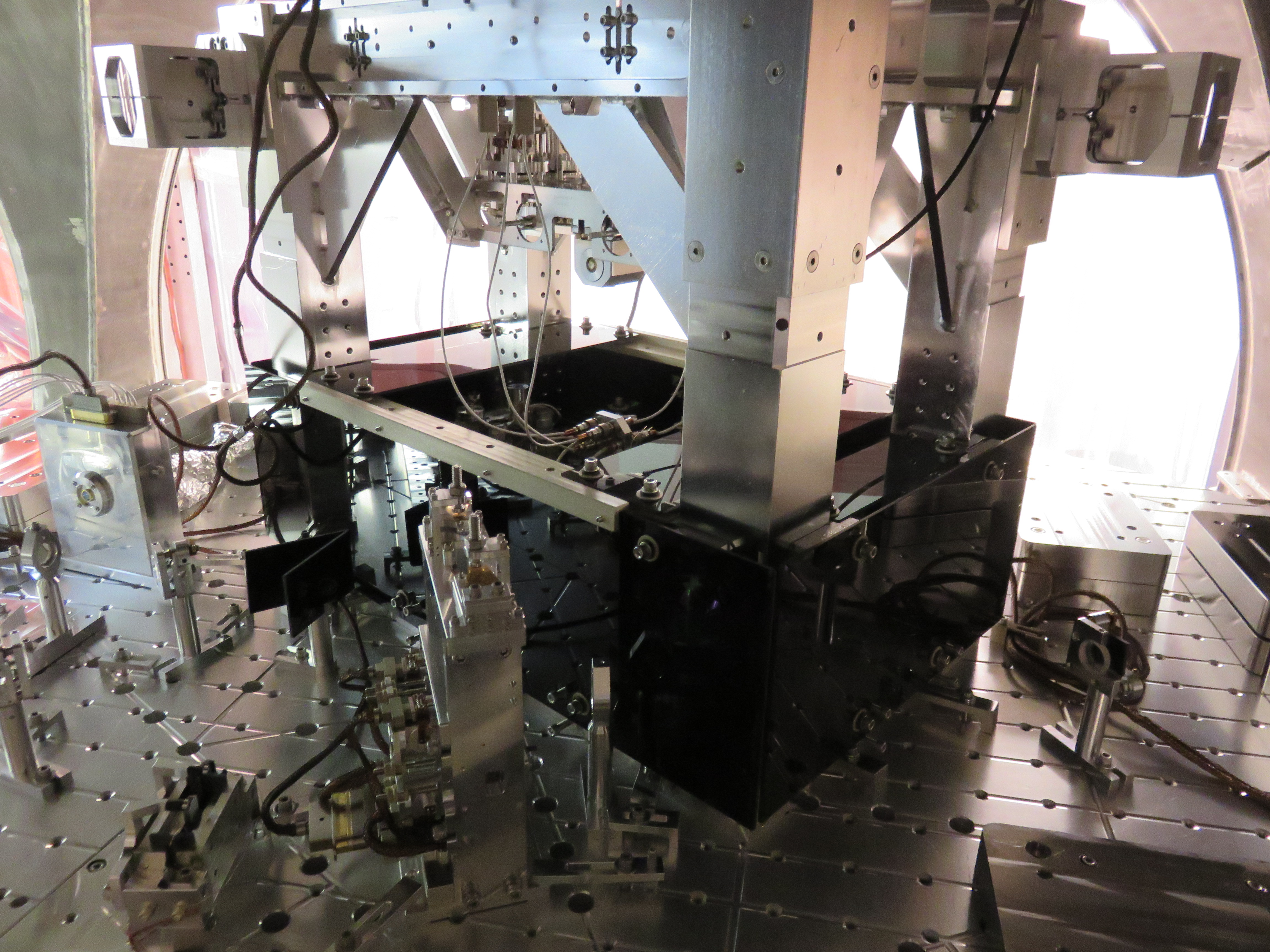
2435...The OMC glass shroud with the two upper glass plates removed. It doesnt look as impressive :-(
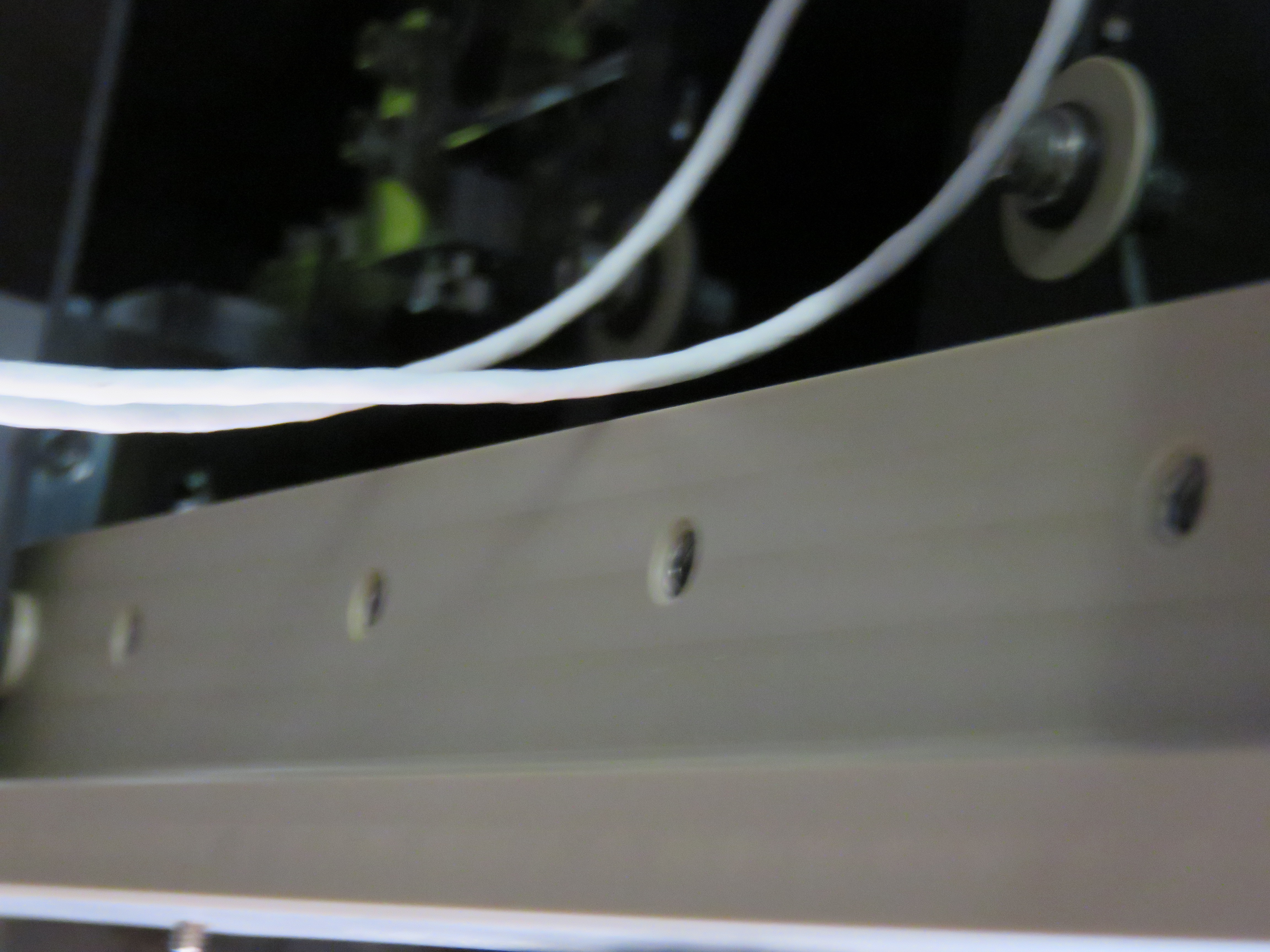
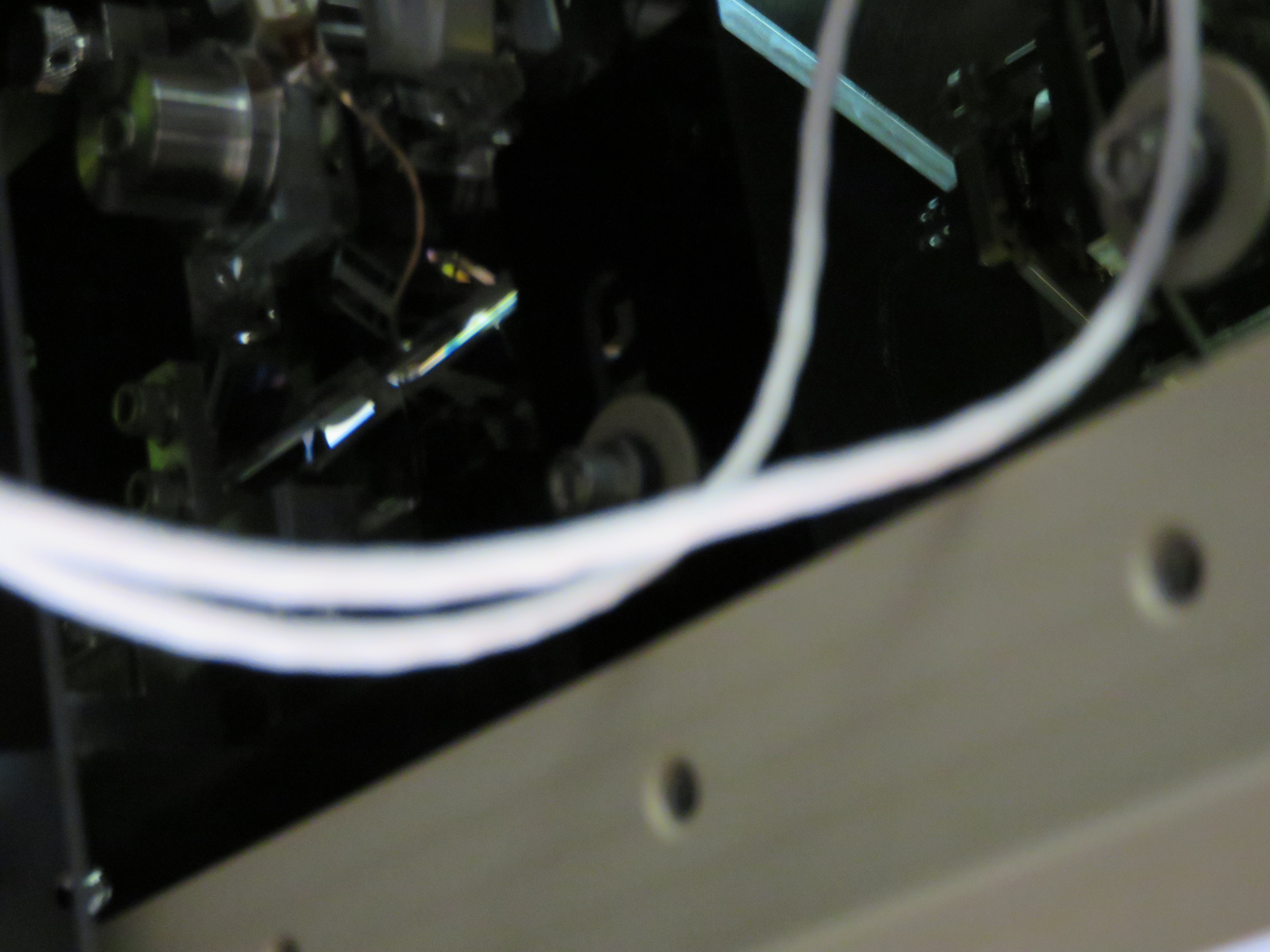
2431 & 2434..how close the cables are to the peek support with glass removed.
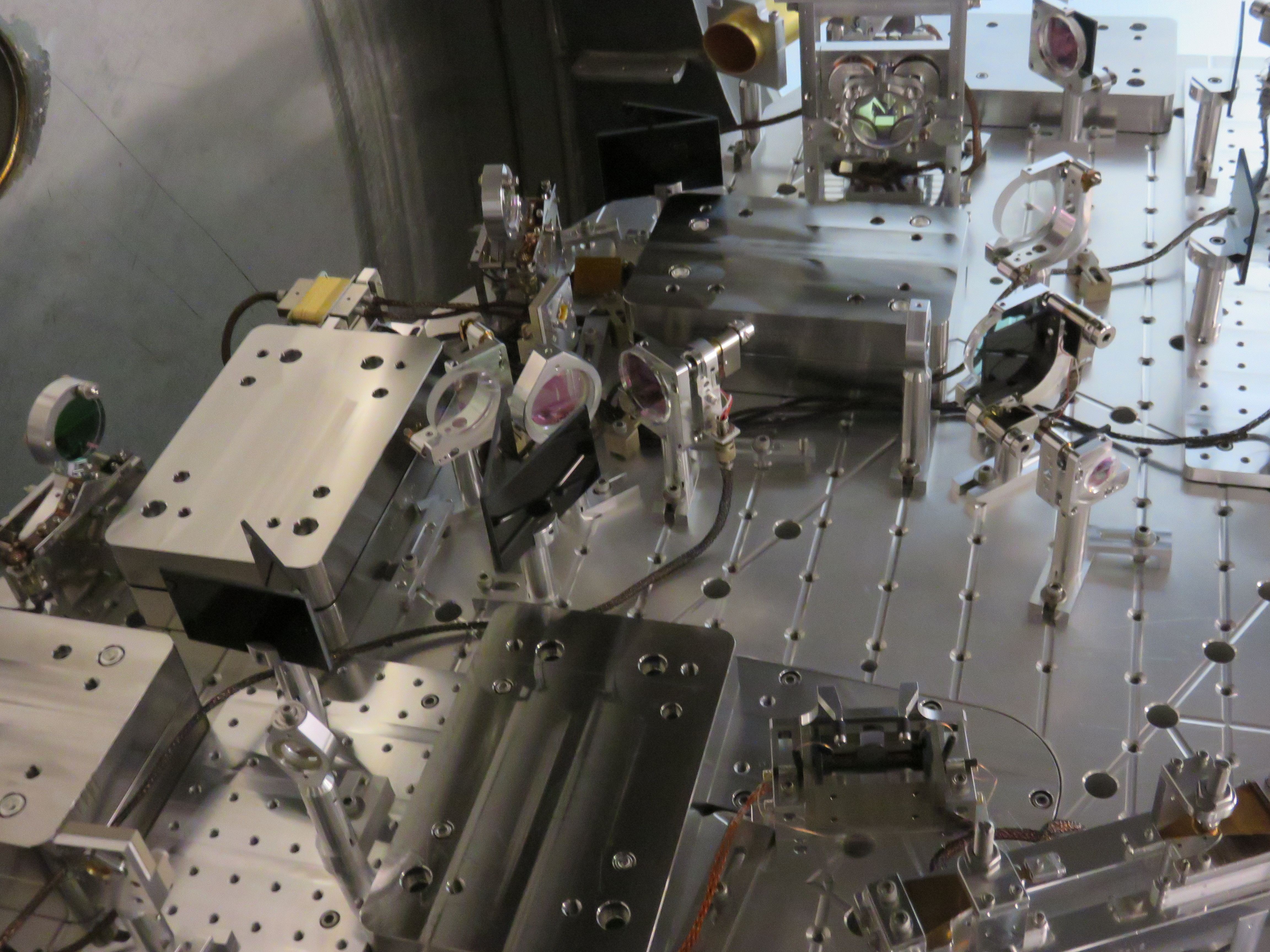
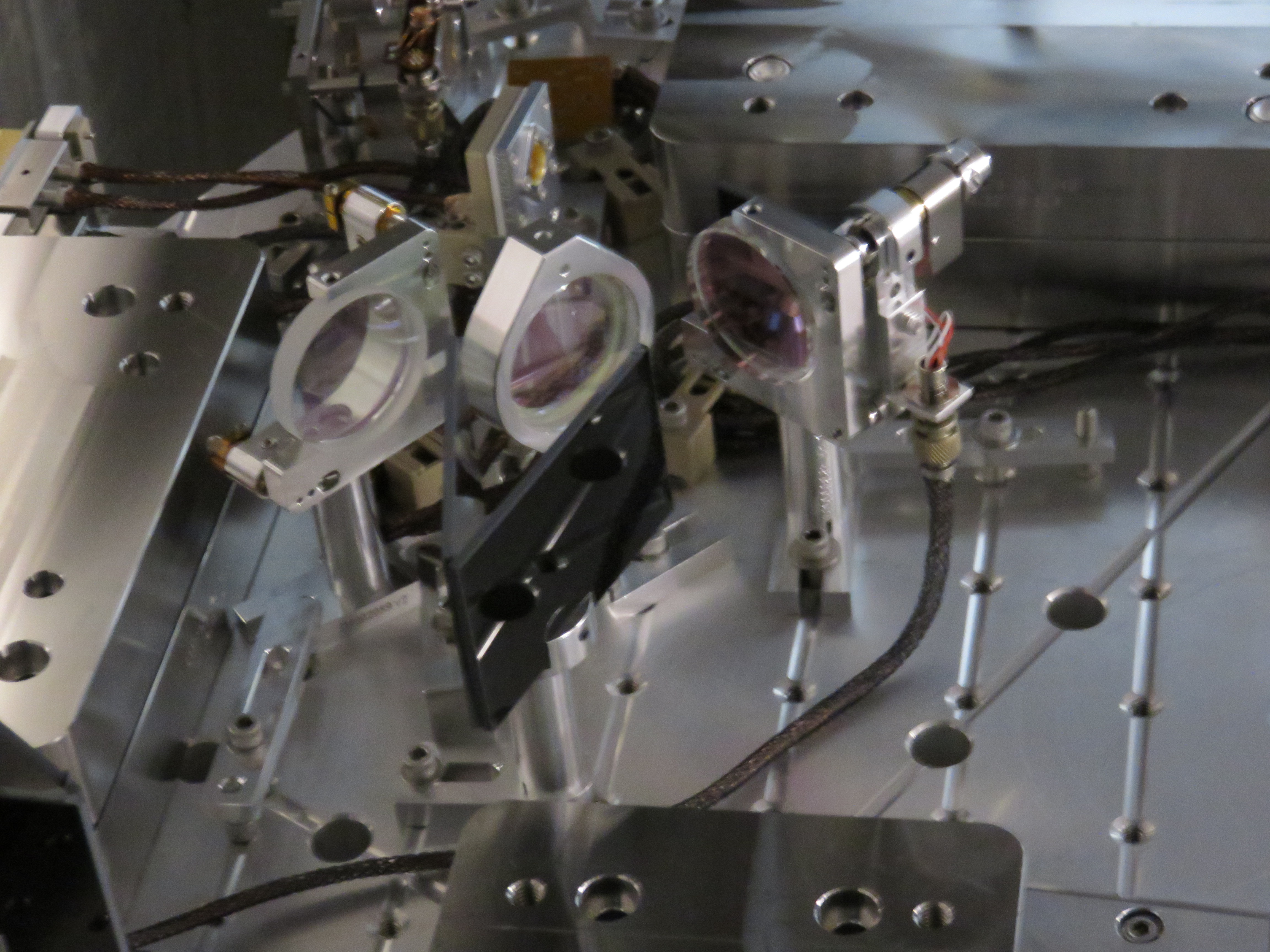
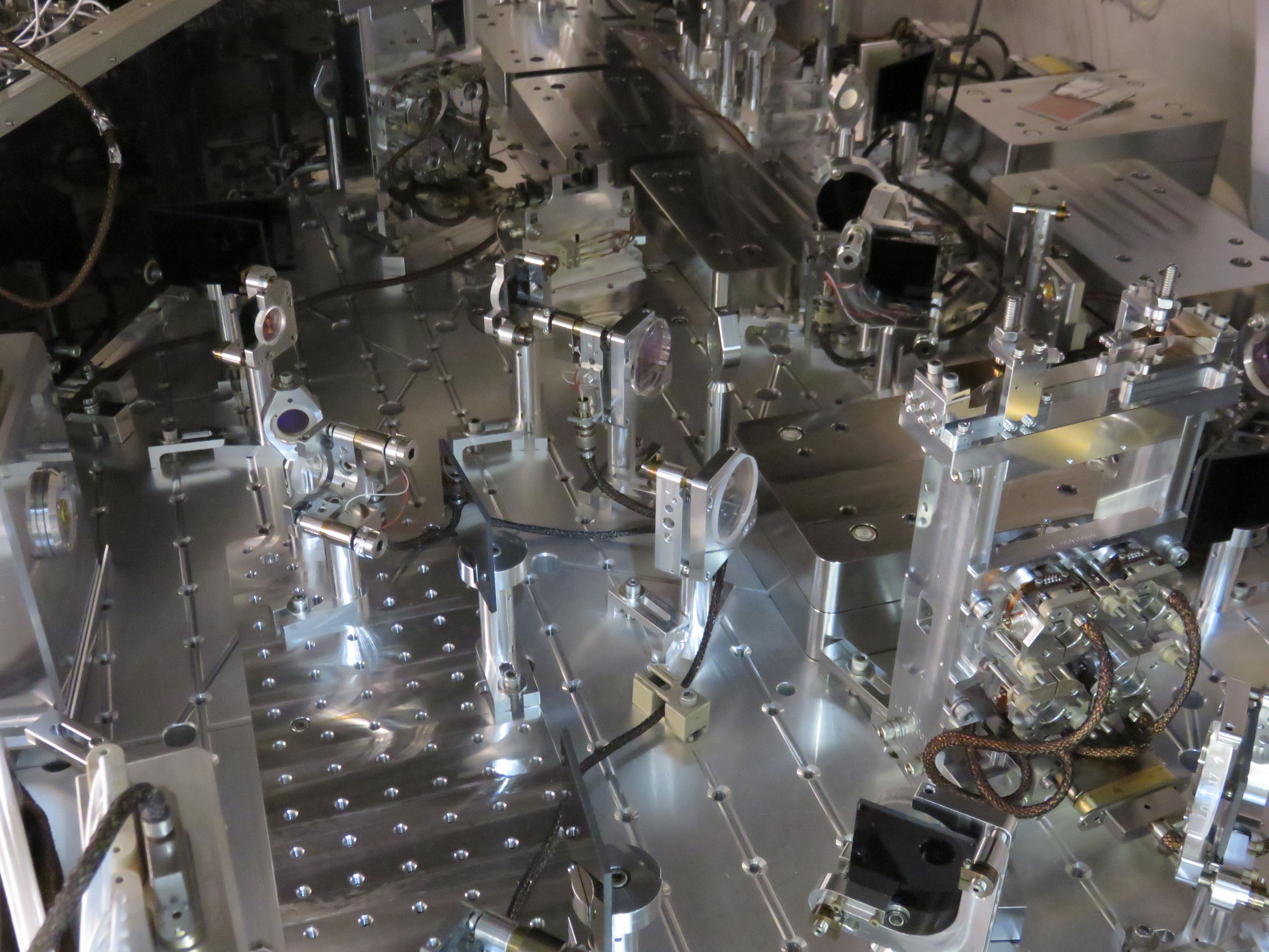
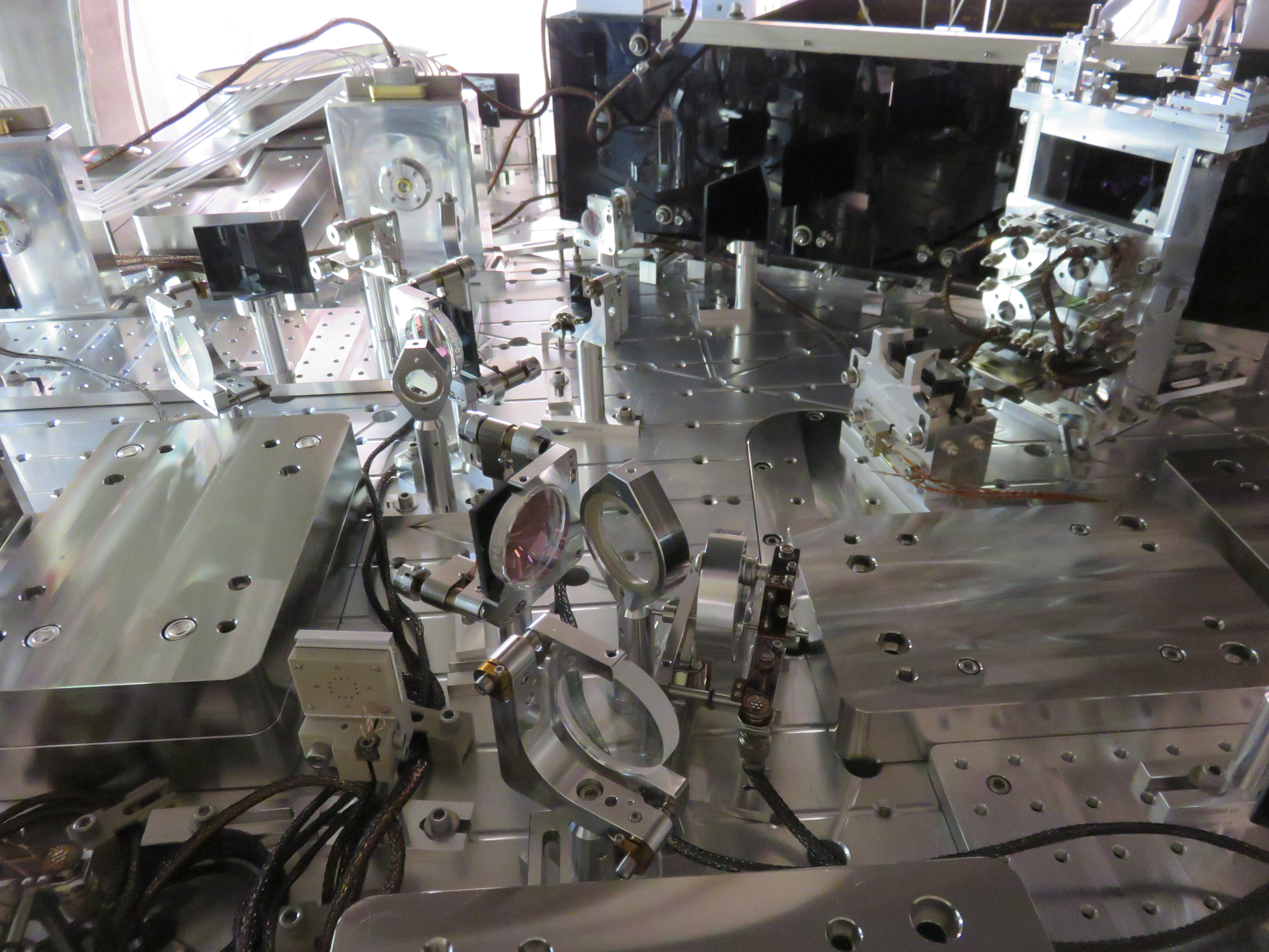
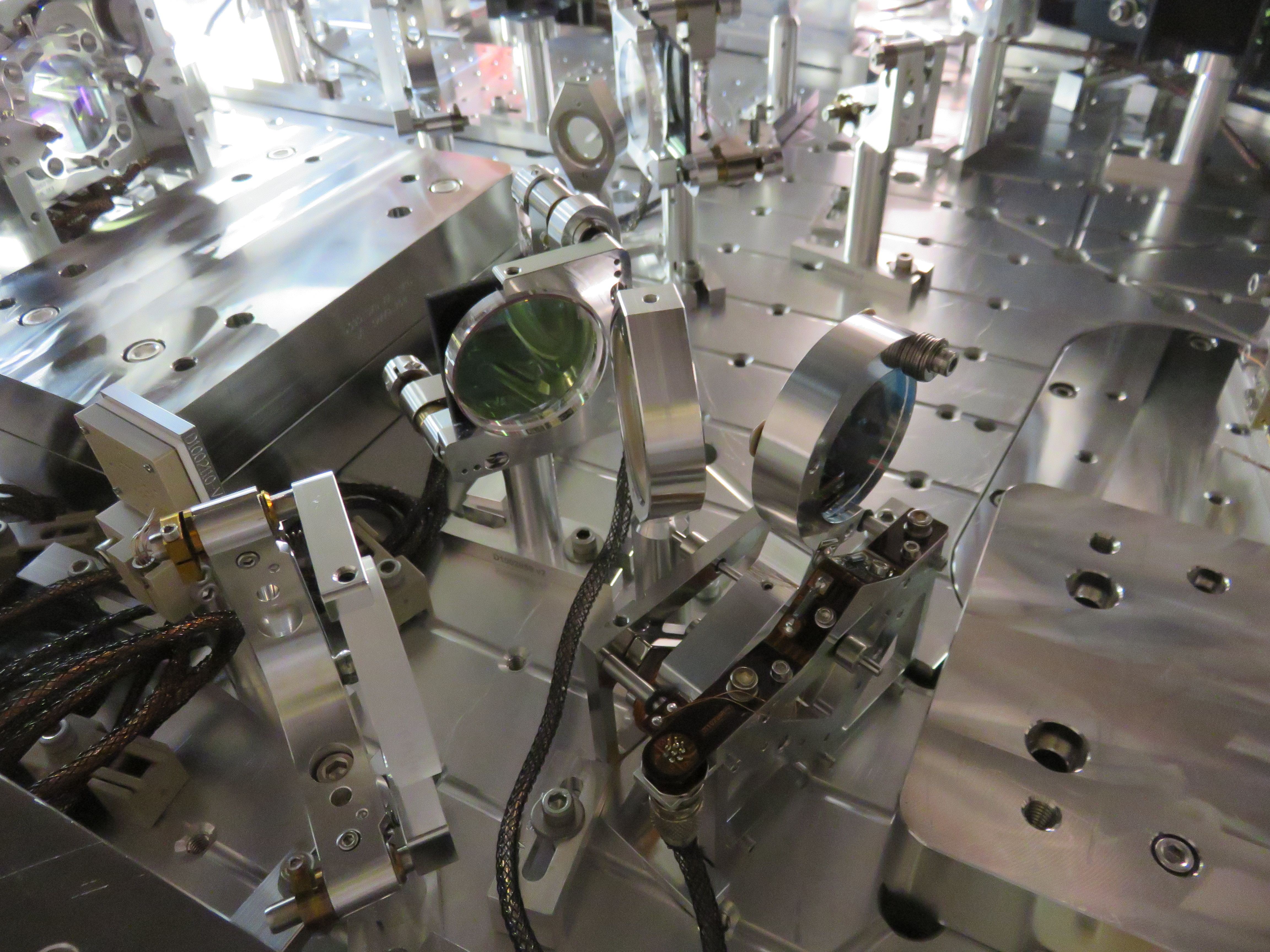
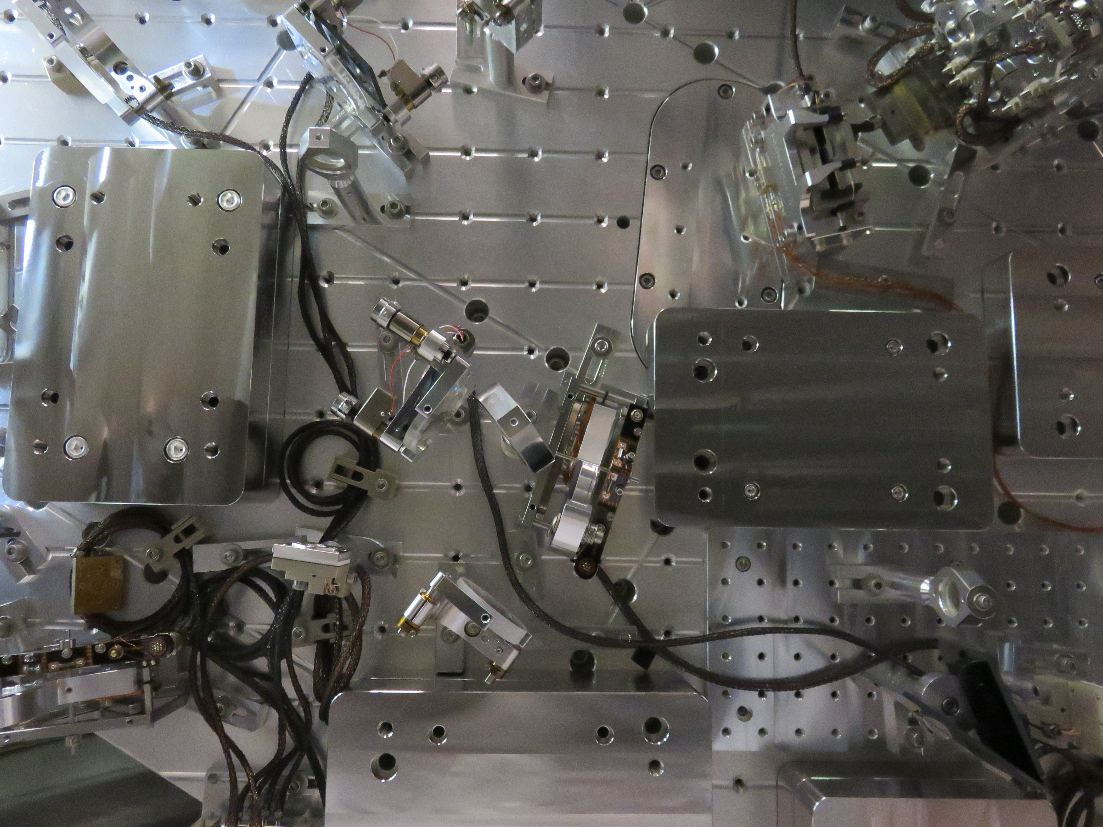
2410 & 2412....beam diverter, V glass beam dumps (both), and beam splitter before move of beam diverter
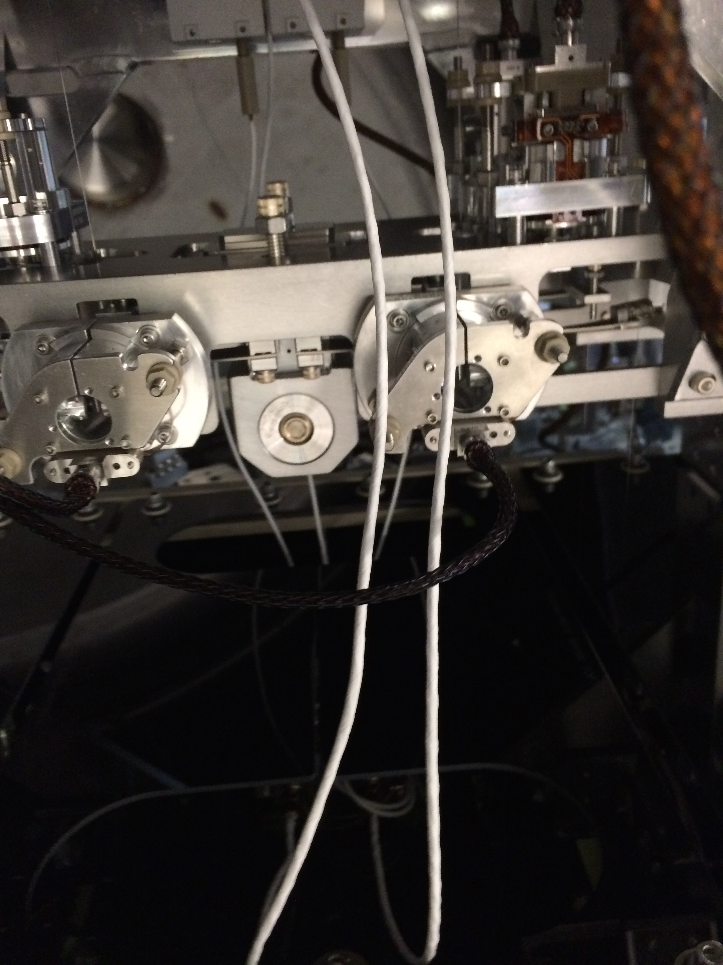
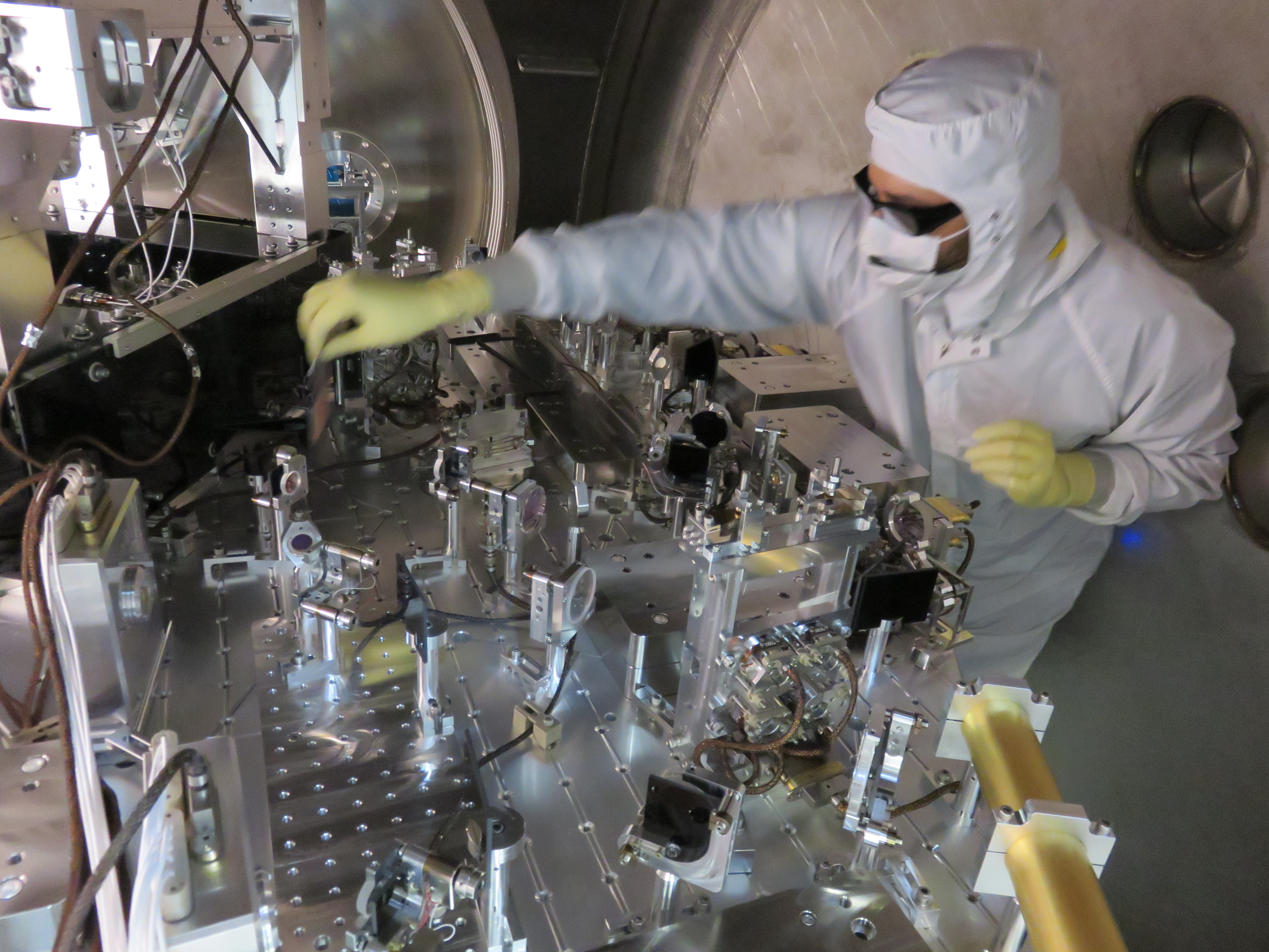
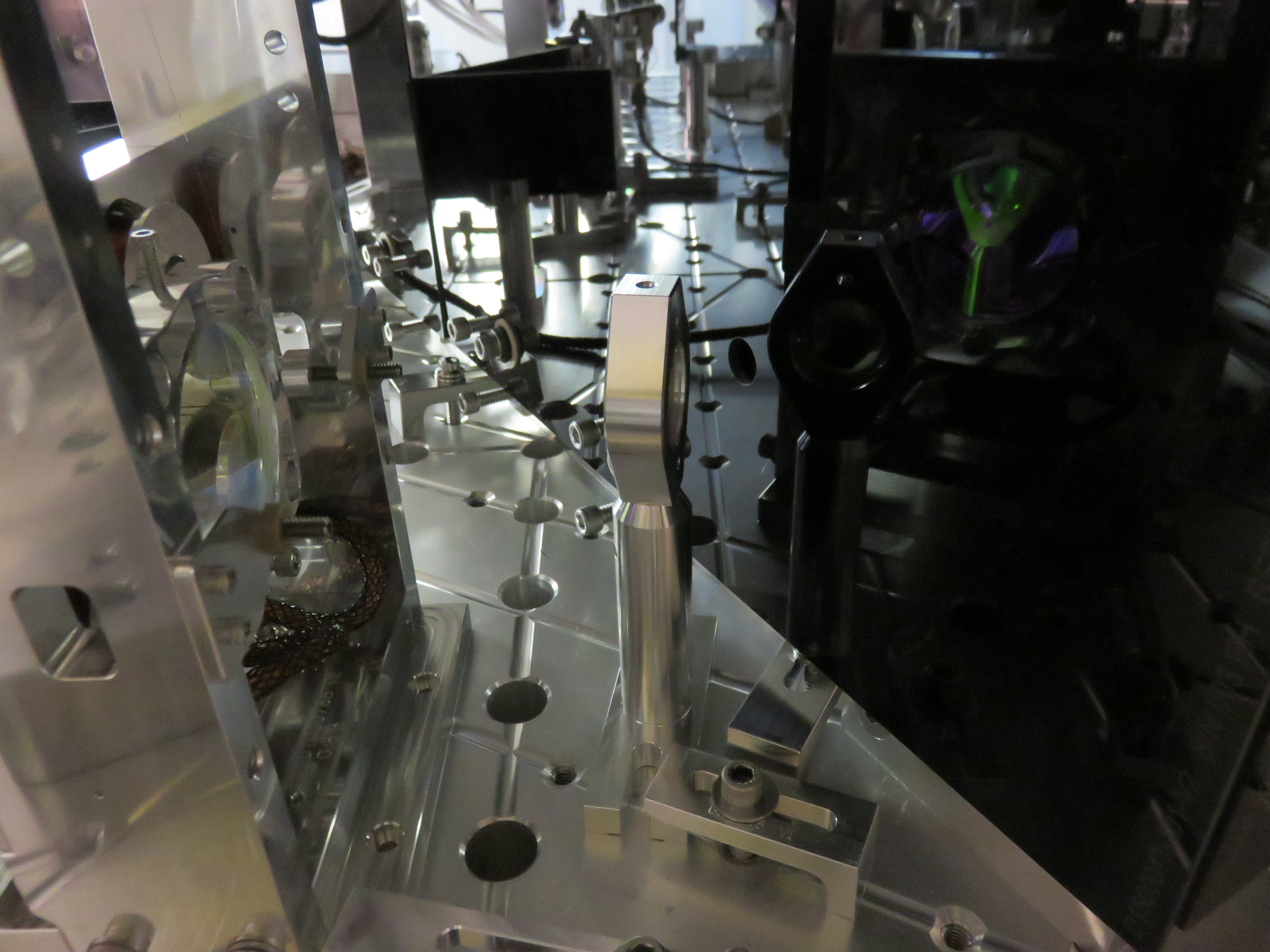
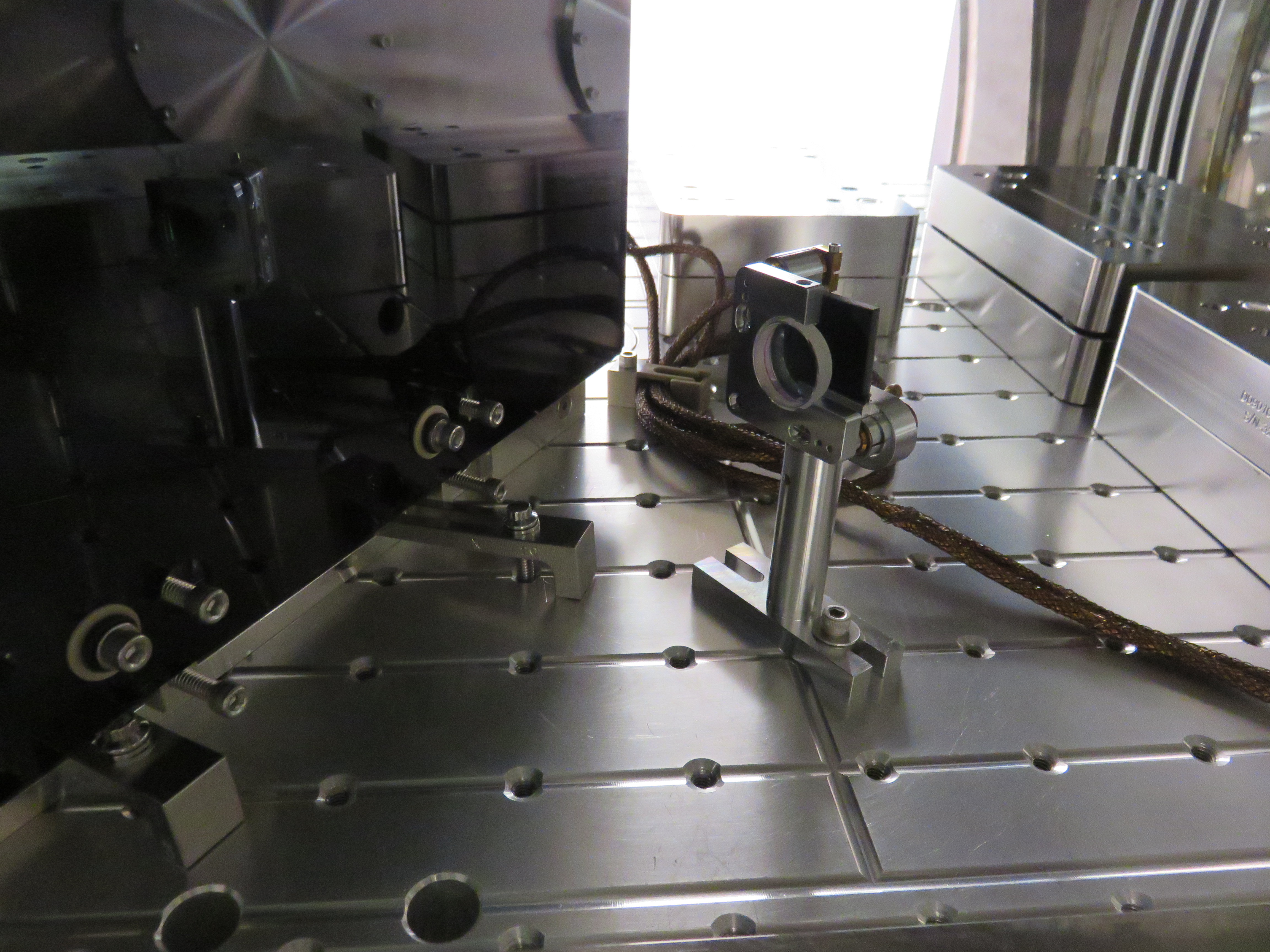
2441 & 2442....playing wiht cables on OMC and checking alignment of beams into and out of OMC shroud
2445, 2449, 2451 & 2453.....the beam diverter, V balck glass dumps (ne for beam diverter and one for beam splitter) and beam splitter after beam diverter move
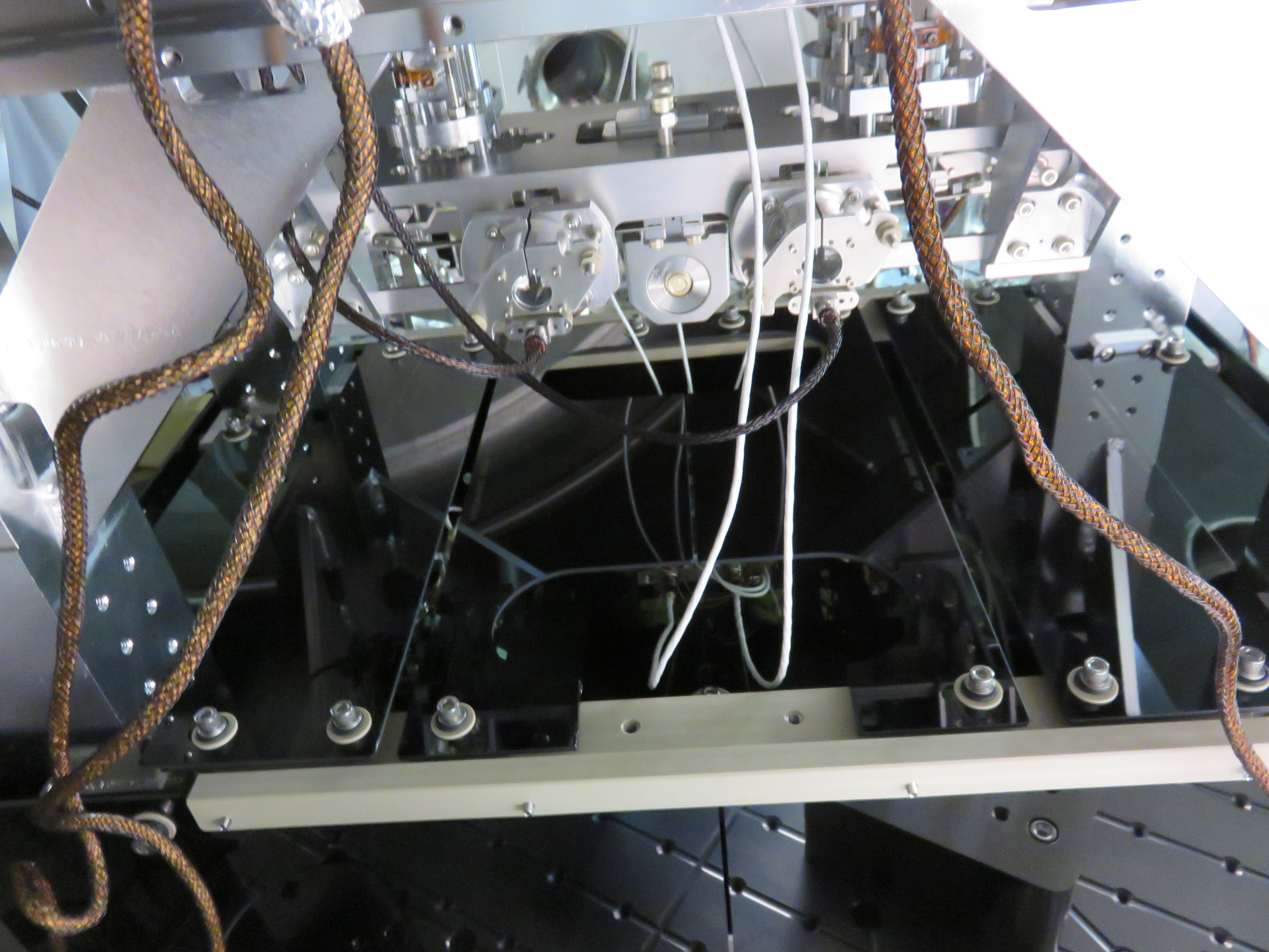
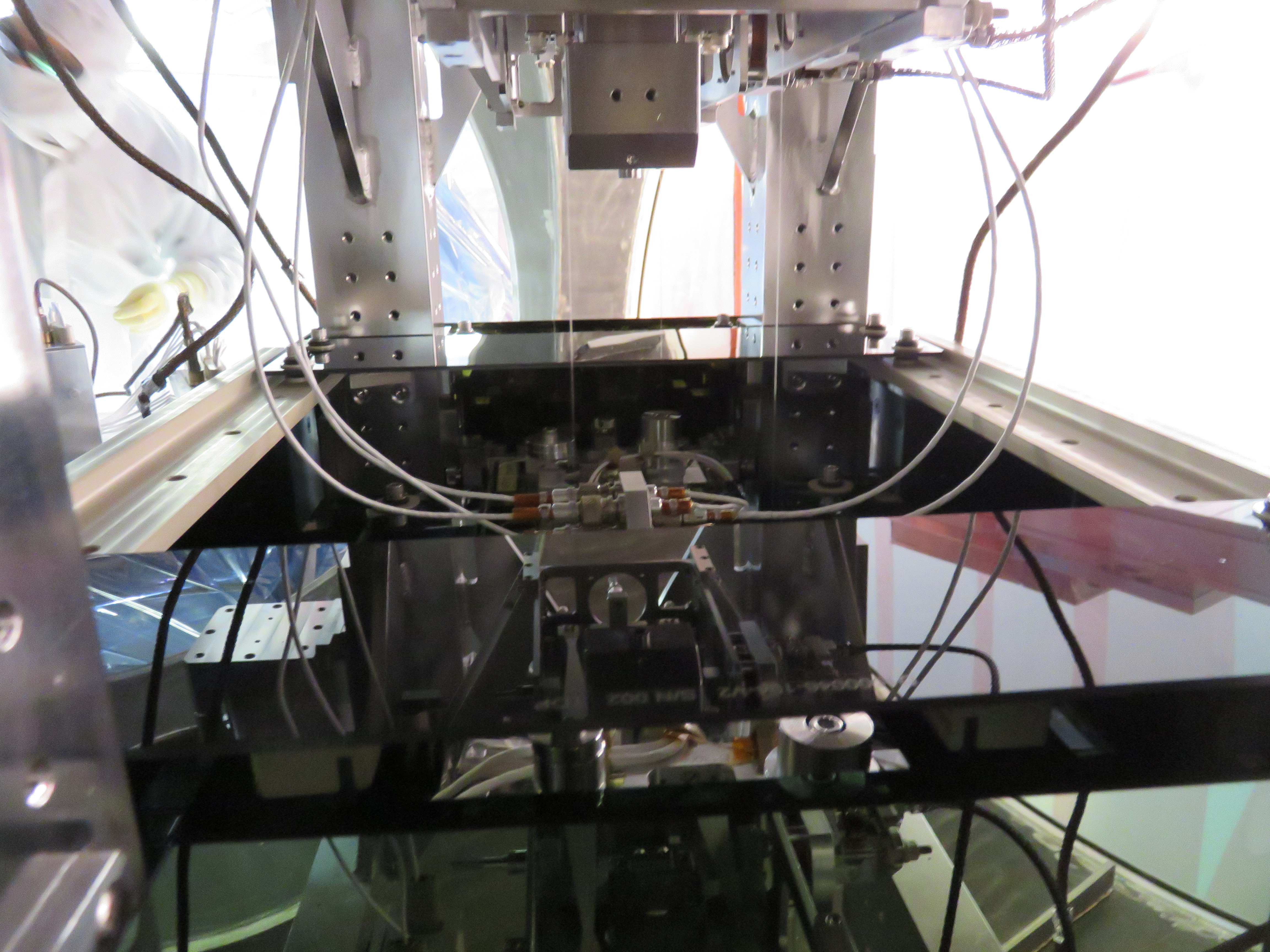
2454 & 2455...the "holes" in the OMC black glass shroud that the beams go in and out of
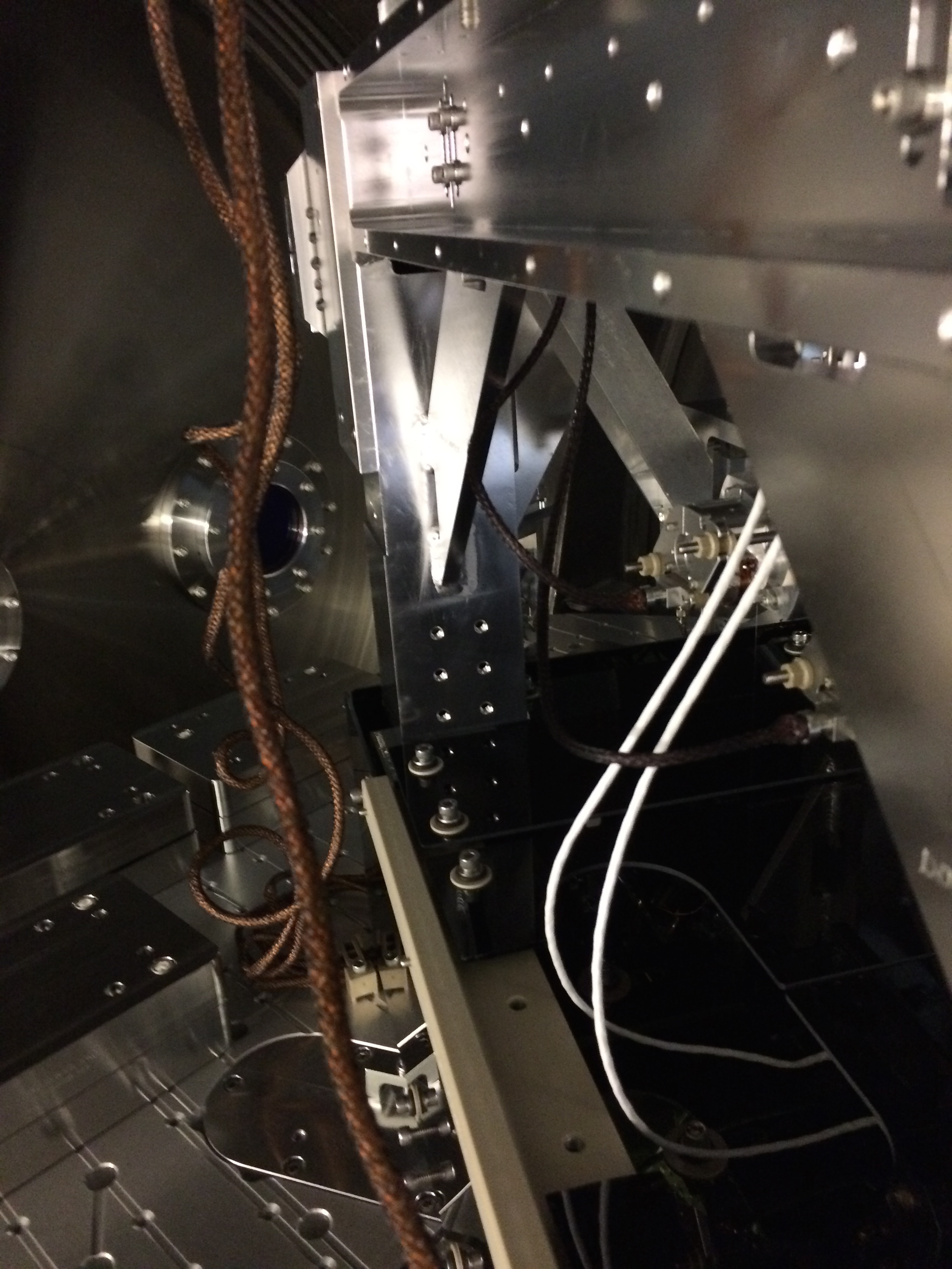
2457, 2460, 2461...the OMC black glass shroud from a different angle (with the two glass panels missing)