[Mackenzie, Paul]
Yesterday we had trouble getting a large enough beat signal between the aux laser and the main PSL. After discussions with Dave O., Stefan and Daniel, we were convinced that the aux laser was not operating monochromatically. This can apparently occur if the aux laser is close to a "mode hop" region when we bring its frequency close to the PSL frequency using the temperature control. We then end up observing the beat frequency between the PSL and one of the "parasitic" modes of the aux laser, which has a much smaller amplitude than the main mode.
On Daniel's advice, we adjusted the diode input current as well as temperature, in order to give us an additional frequency control option that affected the proximity to the mode hopping region differently to the temperature. After some searching around, we suddenly observed a forest of peaks, with one especially large peak.
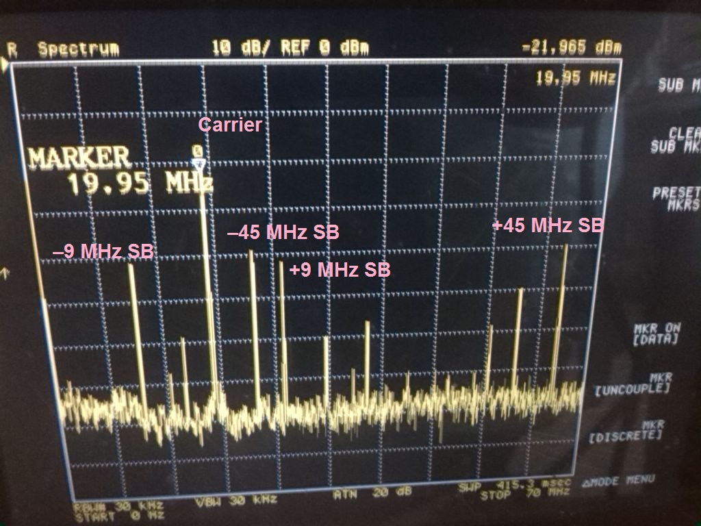
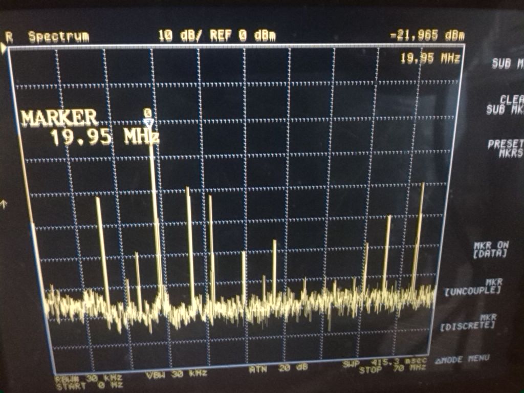
This forest appears to have been a combination of a) saturation of the 1811 AC output exciting harmonics of the base beat frequency and b) contributions from RF sidebands of the PSL light. We reduced the power on the 1811 using the filter wheel (we ended up using the OD 2.5 filter), resulting in the spectrum shown in the attached figure. The VCO offset frequency was 20MHz. Interestingly, the beat between aux laser and 9, 45MHz sidebands are quite visible.
The dominant beat frequency now registers a -22dBm signal at the AC PD output on the spectrum analyzer, even with the power on the PD attenuated such that the DC output from the PD produced by the PSL beam is less than 1mV (the PSL beam is the weaker of the two beams at the PD). This may still seem a little weak, but it is much better than yesterday, when we had ~-50dBm AC on a ~100mV DC signal.
After some adjustment of the servo box gains, we were able to achieve stable PLL locks. There is no slow temperature servo path included yet, so the PZT on the aux laser will go out of range rapidly if the temperature dial is not adjusted by hand. By adjusting the temperature dial, it was possible to keep the PLL locked for tens of minutes.
Next, we switched the frequency reference for the PLL offset from the Marconi VCO to the swept sine output of the network analyzer. This presents a new challenge, because now not only does the aux laser have to phase lock to the PSL, but it also has to track the offset frequency generated by the NA. After playing around with IF BW, sweep ranges, source power etc., we were eventually able to get the aux laser to reliably phase lock to the PSL and track the NA frequency through a ~2MHz frequency range (almost enough for a full PRC sweep). We convinced ourselves that the PLL was locked and tracking the NA frequency by observing the TF from NA drive signal to 1811 AC output. When the PLL is locked, the TF is flat, high, and smooth, since the 1811 AC output is coherent with the NA signal at the same frequency. When the PLL is unlocked, the same TF is many decades smaller.
Each time the NA reaches the end of a sweep and flips back to the start frequency, the lock drops. I'm not sure there's much we can do about that. It would help to have the slow path enabled though, in order to compensate for slow drifts of the aux laser frequency away from the PSL frequency.
Next we plan to try some PRC sweeps if there is PRMI locked time available. For this, we will take the TF from NA drive signal to one of the REFL AIR broadband detectors, with the PRMI locked and the PLL locked. Depending on how that goes, we may pursue the slow temperature feedback development.