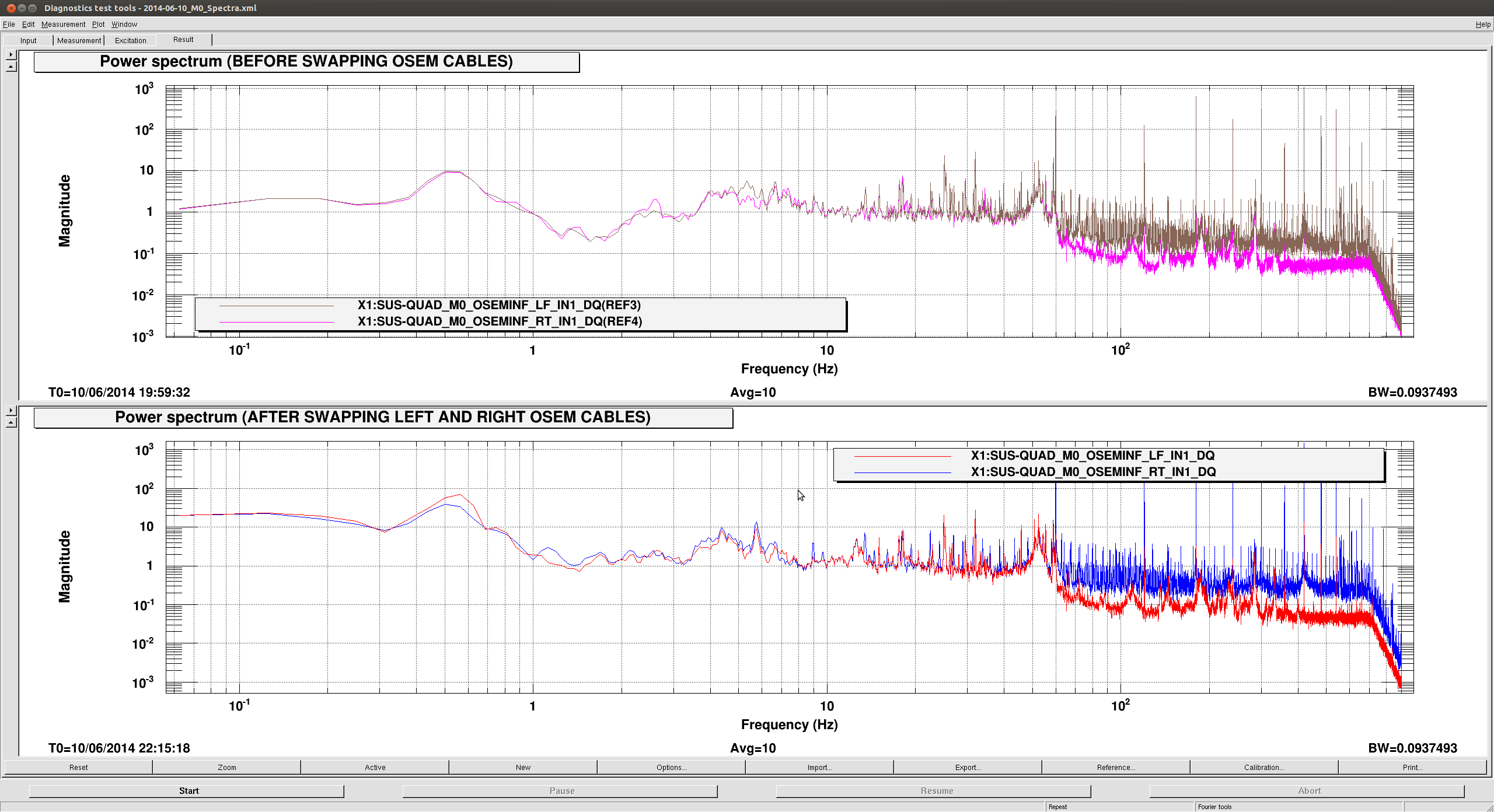
cyrus.reed@LIGO.ORG - posted 14:58, Tuesday 10 June 2014 - last comment - 11:41, Wednesday 11 June 2014(12287)
Switch Firmware Upgrade Notes
Switch Firmware Upgrade Notes
These are the full details of today's switch upgrades.
The core switch (sw-msr-core) ROMMON was upgraded from 15.0(1r)SG7 to 15.0(1r)SG10. This addresses an issue where the switch may drop into ROMMON if the boot process is interrupted by a powercycle if the config-register ends in 0x2. (We use 0x2102, so it's worthwhile to upgrade). The IOS was upgraded from XE 3.4.0SG to XE 3.4.3SG. This includes some fixes for memory leaks, among many other things.
The various Cisco C2960-C switches were upgraded from IOS 15.0(2)SE2 to 15.0(2)SE6. This includes removing support for creation of type 4 password hashes, which were demonstrated to be weaker than the type 5 password hashes they were meant to replace (Crypto is Hard(tm)). These swtiches are: sw-gc-cdsadmin, sw-mech-aux, sw-psl-aux, sw-mx-aux, sw-my-aux.
All Cisco 3560-X switches were likewise upgraded from IOS 15.0(2)SE2 to 15.0(2)SE6, with same notes as above. In addition there was an ASIC microcode update. These switches are: sw-ex-aux, sw-ey-aux, sw-lvea-aux, sw-msr-gc, sw-msr-ops, sw-msr-server1, sw-msr-server2, sw-msr-video2. sw-msr-gc and sw-msr-video2 show an amber SYST LED after reboot indicating some kind of POST failure. I rebooted sw-msr-video2 and according to the console it passes all the POST tests though the LED remained amber. These switches appear to be operating, so I will have to look into this more later.
The Netgear GSM72XXv2 FE network switches were upgraded from 8.0.1.27 to 8.1.0.36. This addresses an issue with ssh management access hanging, requiring a reboot to fix, and high idle CPU usage. These switches are: sw-ex-h1daq, sw-ex-h1fe, sw-ey-h1daq, sw-ey-h1fe, sw-msr-h1fe. The odd one out, sw-msr-h1daq, is a different model switch and has not exhibited any issues worth fixing as yet.
The Fujitsu XG2600 switch that is used to broadcast data between the data concentrator and the rest of the DAQ (sw-msr-h1daqbc) was upgraded from V02.00 to V02.02. The older version of firmware is no longer available for download, but there are no release notes for the new version to know for sure what changed.
Switch Firmware Upgrade Notes
These are the full details of today's switch upgrades.
The core switch (sw-msr-core) ROMMON was upgraded from 15.0(1r)SG7 to 15.0(1r)SG10. This addresses an issue where the switch may drop into ROMMON if the boot process is interrupted by a powercycle if the config-register ends in 0x2. (We use 0x2102, so it's worthwhile to upgrade). The IOS was upgraded from XE 3.4.0SG to XE 3.4.3SG. This includes some fixes for memory leaks, among many other things.
The various Cisco C2960-C switches were upgraded from IOS 15.0(2)SE2 to 15.0(2)SE6. This includes removing support for creation of type 4 password hashes, which were demonstrated to be weaker than the type 5 password hashes they were meant to replace (Crypto is Hard(tm)). These swtiches are: sw-gc-cdsadmin, sw-mech-aux, sw-psl-aux, sw-mx-aux, sw-my-aux.
All Cisco 3560-X switches were likewise upgraded from IOS 15.0(2)SE2 to 15.0(2)SE6, with same notes as above. In addition there was an ASIC microcode update. These switches are: sw-ex-aux, sw-ey-aux, sw-lvea-aux, sw-msr-gc, sw-msr-ops, sw-msr-server1, sw-msr-server2, sw-msr-video2. sw-msr-gc and sw-msr-video2 show an amber SYST LED after reboot indicating some kind of POST failure. I rebooted sw-msr-video2 and according to the console it passes all the POST tests though the LED remained amber. These switches appear to be operating, so I will have to look into this more later.
The Netgear GSM72XXv2 FE network switches were upgraded from 8.0.1.27 to 8.1.0.36. This addresses an issue with ssh management access hanging, requiring a reboot to fix, and high idle CPU usage. These switches are: sw-ex-h1daq, sw-ex-h1fe, sw-ey-h1daq, sw-ey-h1fe, sw-msr-h1fe. The odd one out, sw-msr-h1daq, is a different model switch and has not exhibited any issues worth fixing as yet.
The Fujitsu XG2600 switch that is used to broadcast data between the data concentrator and the rest of the DAQ (sw-msr-h1daqbc) was upgraded from V02.00 to V02.02. The older version of firmware is no longer available for download, but there are no release notes for the new version to know for sure what changed.Switch Firmware Upgrade NoteThese are the full details of today's switch upgrades.
These are the full details of today's switch upgrades.
The core switch (sw-msr-core) ROMMON was upgraded from 15.0(1r)SG7 to 15.0(1r)SG10. This addresses an issue where the switch may drop into ROMMON if the boot process is interrupted by a powercycle if the config-register ends in 0x2. (We use 0x2102, so it's worthwhile to upgrade). The IOS was upgraded from XE 3.4.0SG to XE 3.4.3SG. This includes some fixes for memory leaks, among many other things.
The various Cisco C2960-C switches were upgraded from IOS 15.0(2)SE2 to 15.0(2)SE6. This includes removing support for creation of type 4 password hashes, which were demonstrated to be weaker than the type 5 password hashes they were meant to replace (Crypto is Hard(tm)). These swtiches are: sw-gc-cdsadmin, sw-mech-aux, sw-psl-aux, sw-mx-aux, sw-my-aux.
All Cisco 3560-X switches were likewise upgraded from IOS 15.0(2)SE2 to 15.0(2)SE6, with same notes as above. In addition there was an ASIC microcode update. These switches are: sw-ex-aux, sw-ey-aux, sw-lvea-aux, sw-msr-gc, sw-msr-ops, sw-msr-server1, sw-msr-server2, sw-msr-video2. sw-msr-gc and sw-msr-video2 show an amber SYST LED after reboot indicating some kind of POST failure. I rebooted sw-msr-video2 and according to the console it passes all the POST tests though the LED remained amber. These switches appear to be operating, so I will have to look into this more later.
The Netgear GSM72XXv2 FE network switches were upgraded from 8.0.1.27 to 8.1.0.36. This addresses an issue with ssh management access hanging, requiring a reboot to fix, and high idle CPU usage. These switches are: sw-ex-h1daq, sw-ex-h1fe, sw-ey-h1daq, sw-ey-h1fe, sw-msr-h1fe. The odd one out, sw-msr-h1daq, is a different model switch and has not exhibited any issues worth fixing as yet.
The Fujitsu XG2600 switch that is used to broadcast data between the data concentrator and the rest of the DAQ (sw-msr-h1daqbc) was upgraded from V02.00 to V02.02. The older version of firmware is no longer available for download, but there are no release notes for the new version to know for sure what changed.

The source of the mystery SYST amber LED on sw-msr-gc and sw-msr-video2 are bad power supply fans; one each per switch, both in PS1. The fans appear to operate, and come back OK for a while if the supply is reinserted, so they are probably just running out of spec in some fashion. I'll either swap out the supplies, or see if just the fans can be replaced, as time allows.