I started to try to commision the slow feedback to ETMX again. (We previously had this working, but had never charachterized it, and it was causing pitch problems. I would like to have a feedback to both HEPI and the top mass, and Arnaud has been working on L2P decoupling.)
It seems like the L2P filter right now is unstable, the optic is pitched around alot everytime I try to engage it. Currently I have a X arm gain of -0.8, the notch in MO_LOCK_L, and no boost. The feedback is stable, but the UGF is low. The guardian is set up to set these settings, and running tonight.
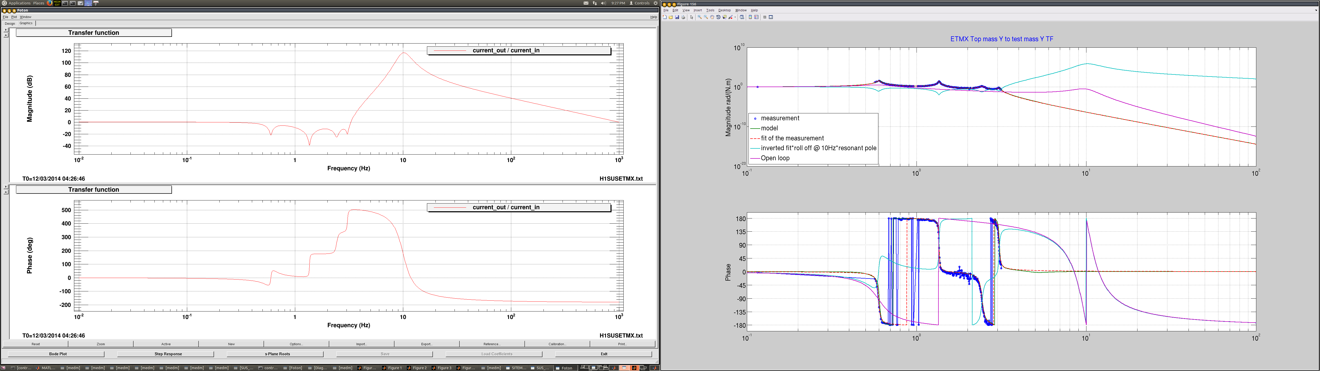
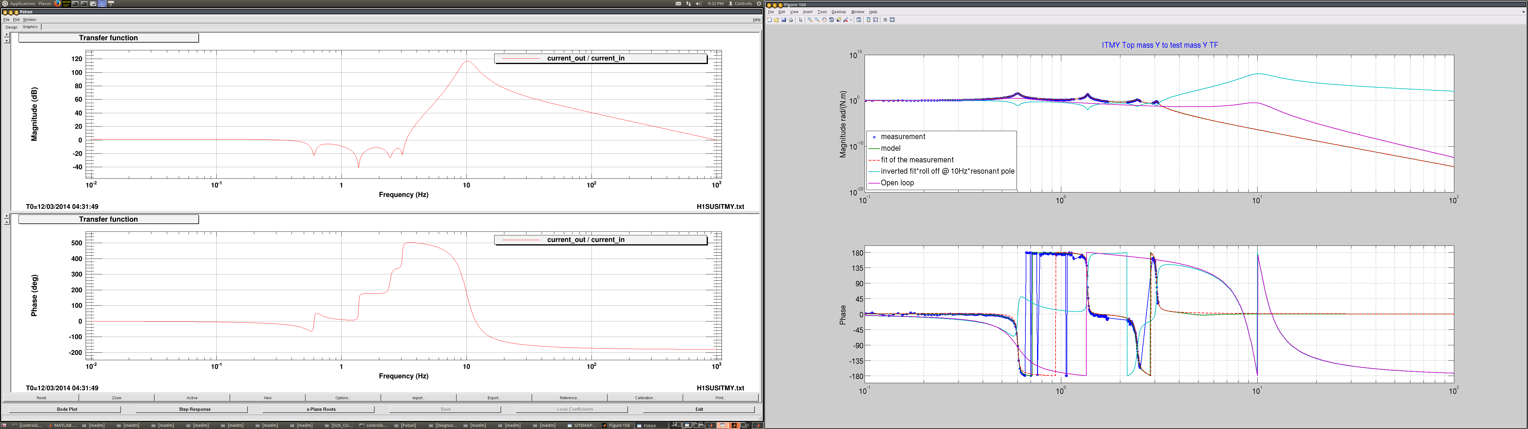
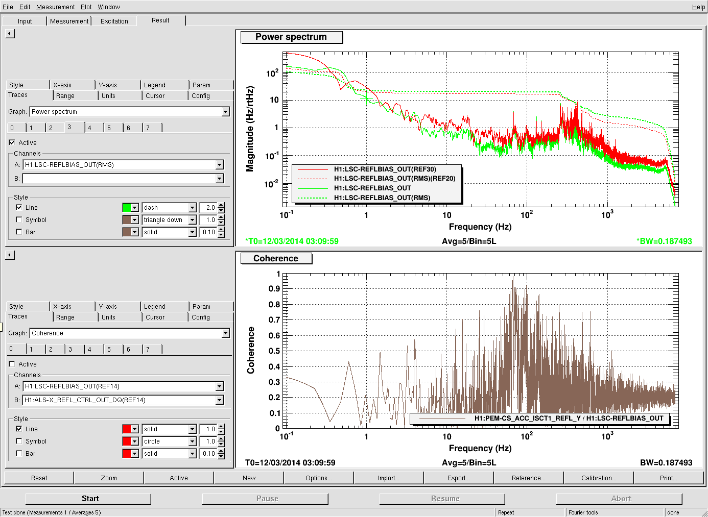
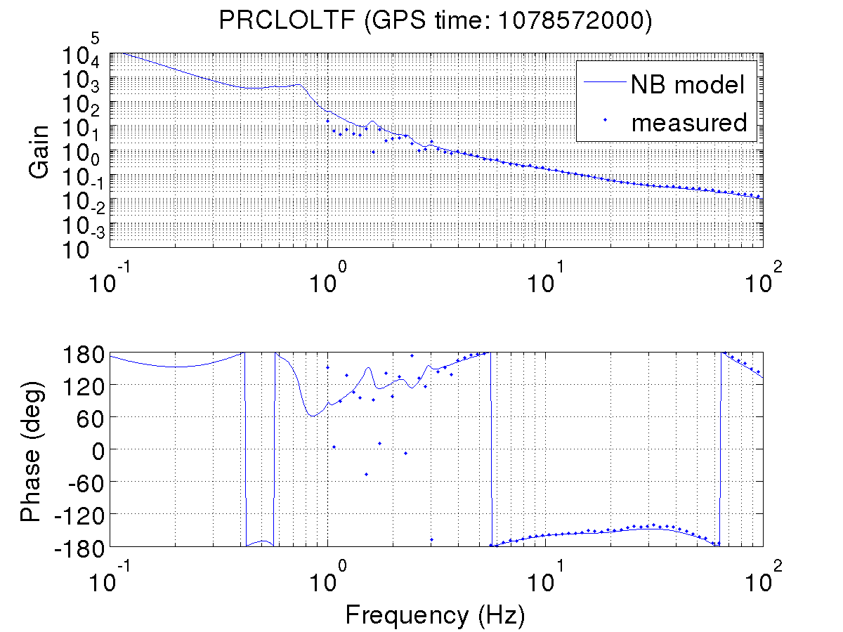
From the transfer function measurements I've made (none of which have verry good coherence) it seems like we should be able to increase the gain, the problem is that we start to excite pitch too much and loose lock.
If opwsws4 has not crashed by morning, would someone from the red team hit save on my dtt session, please? Thank you.

Your data is saved and ETMX is misaligned now.