We (CW and Stochastic folks) are starting to look at the HIFO X data. Greg has generated some Fscans using 30-minute SFTs from a long lock stretch of a number of ALS channels, including the one we are treating as our primary "h(t)" for line finding: H1_ALS-X_ARM_IN1_DQ. The ALS Fscans generated so far are for a long lock stretch (~20 hours) on Feb 2-3 and a 1-day "control segment" on Feb 16 when the arm was not locked. For defining lock, we require mean(H1:ALS-C_COMM_A_LF_OUT_DQ ) > 1200 counts over a 1-minute period. SFTs require 30 contiguous minutes satisfying this condition. Greg's Fscans can be found at this link.
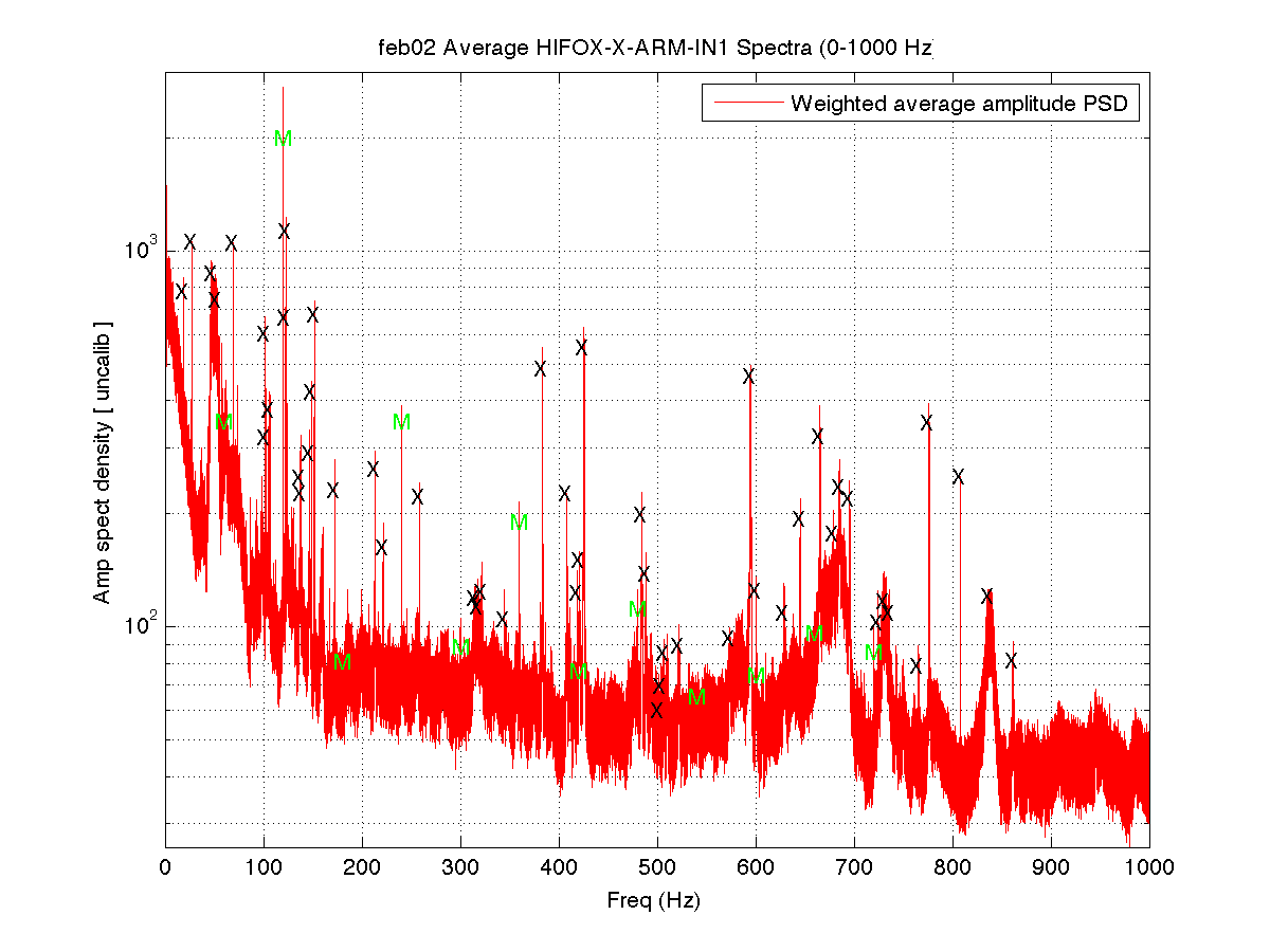
I have taken a quick look at the raw integrated spectrum over all of the Fscan SFTs for the 1st kHz of the feedback channel above to see what narrow lines jump out in the Feb 2-3 data. As for the HIFO Y test, there are many lines visible, and presumably more will become visible, once we have more long stretches to integrate over. Here is a tentative list of frequencies that stand out to some degree. More significant digits are given for sharper lines:
18.425 Hz, 27.743 Hz, 48. 52 Hz, 69.2 Hz, 101.6 Hz, 102.1 Hz, 106.4 Hz, 122.1 Hz, 123.5 Hz, 137 Hz, 138.4 Hz, 146.5 Hz, 148.7 Hz, 151.8 Hz, 172.3 Hz, 213.2 Hz, 221.6 Hz, 258.5 Hz, 315. Hz, 317.5 Hz, 322. Hz, 344.8 Hz, 383.7 Hz, 408.4 Hz, 418.5 Hz, 421.2 Hz, 425.7 Hz, 484.5 Hz, 488.4 Hz, 501.5 Hz, 504.2 Hz, 506.7 Hz, 522. Hz, 573.5 Hz, 594.8 Hz, 600.8 Hz, 628.8 Hz, 645.3 Hz, 665.5 Hz, 678.8 Hz, 685.2 Hz, 695.5 Hz, 724.6 Hz, 730.5 Hz, 735.5 Hz, 765.5 Hz, 776.3 Hz, 808.213 Hz, 837.5 Hz, 861.5 Hz
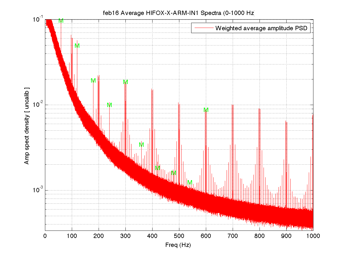
I also took a look at the same channel when the arm was not locked (Feb 16 data) and found a pervasive digital comb (lines are entirely contained in the 0.5-mHz bins) on top of a comb. There is a 100-Hz comb up to and beyond 4 kHz, with a comb of odd-harmonics of 3.125 Hz (=100/32) centered on each 100-Hz harmonic. The spacing between the secondary comb harmonics is 6.25 Hz (=100/16). For example, one sees 190.625 Hz, 196.875 Hz, 200 Hz, 203.125 Hz, 209.375 Hz, with the secondary combs from 200 Hz and 300 Hz joining smoothly at 246.875 Hz and 253.125 Hz. Lines at this strength are not visible in the locked-arm data on Feb 2, but it would be worrisome to future CW searches to have coherent digital lines at even this low level.
More information on H1 HIFO X line-finding plans and tools (e.g. NoEMi) can be found on this wiki page. Comments are welcome.
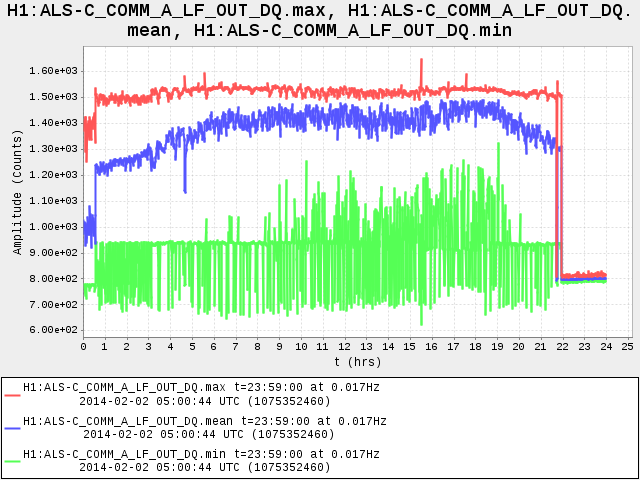
Figure 1 - minute trends (min,mean,max) of H1:ALS-C_COMM_A_LF_OUT_DQ on Feb 2 (arm locked to green light)
Figure 2 - uncalibrated spectrum of H1_ALS-X_ARM_IN1_DQ on Feb 2. Power mains marked with 'M'. Single lines marked with 'x'
Figure 3 - uncalibrated spectrum of H1_ALS-X_ARM_IN1_DQ on Feb 16 (unlocked). Power mains marked with 'M'. The comb-on-comb structure is apparent.
 This is why I didn't see a reasonable signal out of it.


That was me, sorry.