Jennie, Camilla, Vicky
I used Craig and Camilla's code in /ligo/gitcommon/noise_recorder to measure the DARM OLG and the PCAL to DARM TF in order to look at the SRC detuning over thermalisation and whether we can change it.
To measure the DARM TF use:
darm_noise_injection_caller.py
but change the common_name_prefix to reflect your specific measurement (ie. SRCL1 offset).
pcal_noise_injection_caller.py
but change the common_name_prefix to reflect your specific measurement (ie. SRCL1 offset).
darm_sensing_function_processor.py
make sure the .hdf5 filenames for the pcal and darm measurements are correct, and make sure you have updated date_str to reflect the correct date and label_prefix to reflect the common name label of the two measurements. Also copy across the PCAL measurement to the DARM measurement folder as these will have been saved separately due to different time stamps. Then change date_dir_str to the name of the DARM measurement directory. I just made a new process_sensing_function_measurement() function in the script for each measurement I had to do.
|
SRCL1 OFFSET |
Time Into Lock | DARM Injection Start | PCAL > DARM Injection Start | DARM Measurement hdf5 file | PCAL Measurement hdf5 file | Processed Data Folder (.txt) |
Figures Folder (.pdf) |
| -165 | 3 mins | 1367105753 | 1367105978 | /ligo/gitcommon/noise_recorder/data/darm_noise/202305021635/darm_noise_srcl_-165_src1_p_-6_50_6_50_Hz_gps_start_1367105753.hdf5 | /ligo/gitcommon/noise_recorder/data/darm_noise/202305021639/pcaly_srcl_-165_src1_p_-6_50_6_50_Hz_gps_start_1367105978.hdf5 | /ligo/gitcommon/noise_recorder/data/darm_noise/ | /ligo/gitcommon/noise_recorder/figures/darm_noise/ |
| -165 | 24 mins | 1367107033 | 1367107233 | Processing file 1/1 /ligo/gitcommon/noise_recorder/data/darm_noise/202305021656/darm_noise_srcl_-165_src1_p_-6_50_6_50_Hz_gps_start_1367107033.hdf5 |
/ligo/gitcommon/noise_recorder/data/darm_noise/202305021656/pcaly_srcl_-165_src1_p_-6_50_6_50_Hz_gps_start_1367107233.hdf5
|
Stitched TF file saved at /ligo/gitcommon/noise_recorder/data/darm_noise/202305021656/ |
/ligo/gitcommon/noise_recorder/figures/darm_noise/202305021656/ |
| 0 | 11 mins | 1367112023 | 1367112223 | /ligo/gitcommon/noise_recorder/data/darm_noise/202305021820/darm_noise_srcl_0_src1_p_-6_50_6_50_Hz_gps_start_1367112023.hdf5 |
/ligo/gitcommon/noise_recorder/data/darm_noise/202305021823/pcaly_srcl_0_src1_p_-6_50_6_50_Hz_gps_start_1367112223.hdf5 | /ligo/gitcommon/noise_recorder/data/darm_noise/202305021820/ | /ligo/gitcommon/noise_recorder/figures/darm_noise/202305021820/ |
| +100 | 28 | 1367112998 | 1367113217 | /ligo/gitcommon/noise_recorder/data/darm_noise/202305021836/darm_noise_srcl_+100_src1_p_-6_50_6_50_Hz_gps_start_1367112998.hdf5 | /ligo/gitcommon/noise_recorder/data/darm_noise/202305021839/pcaly_srcl_+100_src1_p_-6_50_6_50_Hz_gps_start_1367113217.hdf5 | /ligo/gitcommon/noise_recorder/data/darm_noise/202305021836/ | /ligo/gitcommon/noise_recorder/figures/darm_noise/202305021836/ |
| 0 | 56 | 1367114970 | 1367115221 | Data file saved at /ligo/gitcommon/noise_recorder/data/darm_noise/202305021909/darm_noise_srcl_0_src1_1hr_in_p_-6_50_6_50_Hz_gps_start_1367114970.hdf5 |
/ligo/gitcommon/noise_recorder/data/darm_noise/202305021913/pcaly_srcl_0_src1_1hr_in_p_-6_50_6_50_Hz_gps_start_1367115221.hdf5 | /ligo/gitcommon/noise_recorder/data/darm_noise/202305021909 | /ligo/gitcommon/noise_recorder/figures/darm_noise/202305021909 |
| -180 | 1.5hrs | 1367116767 | 1367116962 | /ligo/gitcommon/noise_recorder/data/darm_noise/202305021939/darm_noise_srcl_-180_src1_1-5hr_in_p_-6_50_6_50_Hz_gps_start_1367116767.hdf5 | /ligo/gitcommon/noise_recorder/data/darm_noise/202305021942/pcaly_srcl_-180_src1_1-5hr_in_p_-6_50_6_50_Hz_gps_start_1367116962.hdf5 | /ligo/gitcommon/noise_recorder/data/darm_noise/202305021939 | /ligo/gitcommon/noise_recorder/figures/darm_noise/202305021939 |
| -200 | 1hr 50 mins | 1367117947 | 1367118143 | /ligo/gitcommon/noise_recorder/data/darm_noise/202305021958/darm_noise_srcl_-200_src1_1hr48_in_p_-6_50_6_50_Hz_gps_start_1367117947.hdf5 | /ligo/gitcommon/noise_recorder/data/darm_noise/202305022002/pcaly_srcl_-200_src1_1hr48_in_p_-6_50_6_50_Hz_gps_start_1367118143.hdf5 | /ligo/gitcommon/noise_recorder/data/darm_noise/202305021958 | /ligo/gitcommon/noise_recorder/figures/darm_noise/202305021958 |
| -220 | 2 hrs 16 mins into lock | 1367119477 | 1367119682 | /ligo/gitcommon/noise_recorder/data/darm_noise/202305022024/darm_noise_srcl_-220_src1_2hr14_in_p_-6_50_6_50_Hz_gps_start_1367119477.hdf5 | /ligo/gitcommon/noise_recorder/data/darm_noise/202305022027/pcaly_srcl_-220_src1_2hr14_in_p_-6_50_6_50_Hz_gps_start_1367119682.hdf5 | /ligo/gitcommon/noise_recorder/data/darm_noise/202305022024/ | /ligo/gitcommon/noise_recorder/figures/darm_noise/202305022024 |
| -240 | 2 hrs 42 mins into lock | 1367121055 | 1367121265 | /ligo/gitcommon/noise_recorder/data/darm_noise/202305022050/darm_noise_srcl_-240_src1_2hr40_in_p_-6_50_6_50_Hz_gps_start_1367121055.hdf5 | Data file saved at /ligo/gitcommon/noise_recorder/data/darm_noise/202305022054/pcaly_srcl_-240_src1_2hr40_in_p_-6_50_6_50_Hz_gps_start_1367121265.hdf5 |
/ligo/gitcommon/noise_recorder/data/darm_noise/202305022050/ | /ligo/gitcommon/noise_recorder/figures/darm_noise/202305022050 |
| -165 | 3 hrs 3 mins into lock | 1367122300 | 1367122491 | /ligo/gitcommon/noise_recorder/data/darm_noise/202305022111/darm_noise_srcl_-165_src1_3hr3_in_p_-6_50_6_50_Hz_gps_start_1367122300.hdf5 | /ligo/gitcommon/noise_recorder/data/darm_noise/202305022114/pcaly_srcl_-165_src1_3hr3_in_p_-6_50_6_50_Hz_gps_start_1367122491.hdf5 | /ligo/gitcommon/noise_recorder/data/darm_noise/202305022111 | /ligo/gitcommon/noise_recorder/figures/darm_noise/ |
Posting this now to show measurements taken. Will comment tomorrow with all graphs on one plot.
Attached to the report are the compiled plots from both measurements, which are in the data folders listed in the table.
Based on this test, and more measurements of the sensing function today, we have determined that -200 is a better SRCL offset. We don't want to increase much beyond this, to leave enough ADC range on LSC POP 45. I have changed the SRCL offset in the guardian (lownoise length control).
Naoki, Vicky
To fix the FC injection axis, we plan to implement the beam spot control with green QPD or IR camera at FC transmission. First we measured the beam position on FC1/2 with dither method (alog66132) and tried to center them by ZM2/3. The last time when we centered the FC1/2 is reported in alog66662.
We dithered FC1/2 P/Y and tried to minimize the dither lines in FC IR error signal which is much more sensitive than the green error signal. The template is saved in userapps/sqz/h1/Templates/dtt/filter_cavity/FC_dither_IR.xml.
The FC2 dither lines are sensitive to ZM3 and can be removed by moving ZM3. The FC1 dither lines are not very sensitive to ZM2/3. Ideally we should center FC1/2 by moving ZM2/3 as reported in alog66662, but we think that centering the FC2 by ZM3 would be enough to fix the injection beam axis. So we decided to use ZM3 only for beam spot control to center FC2.
We will check the error signal of green QPD and IR camera at FC transmission and will implement the beam spot control.
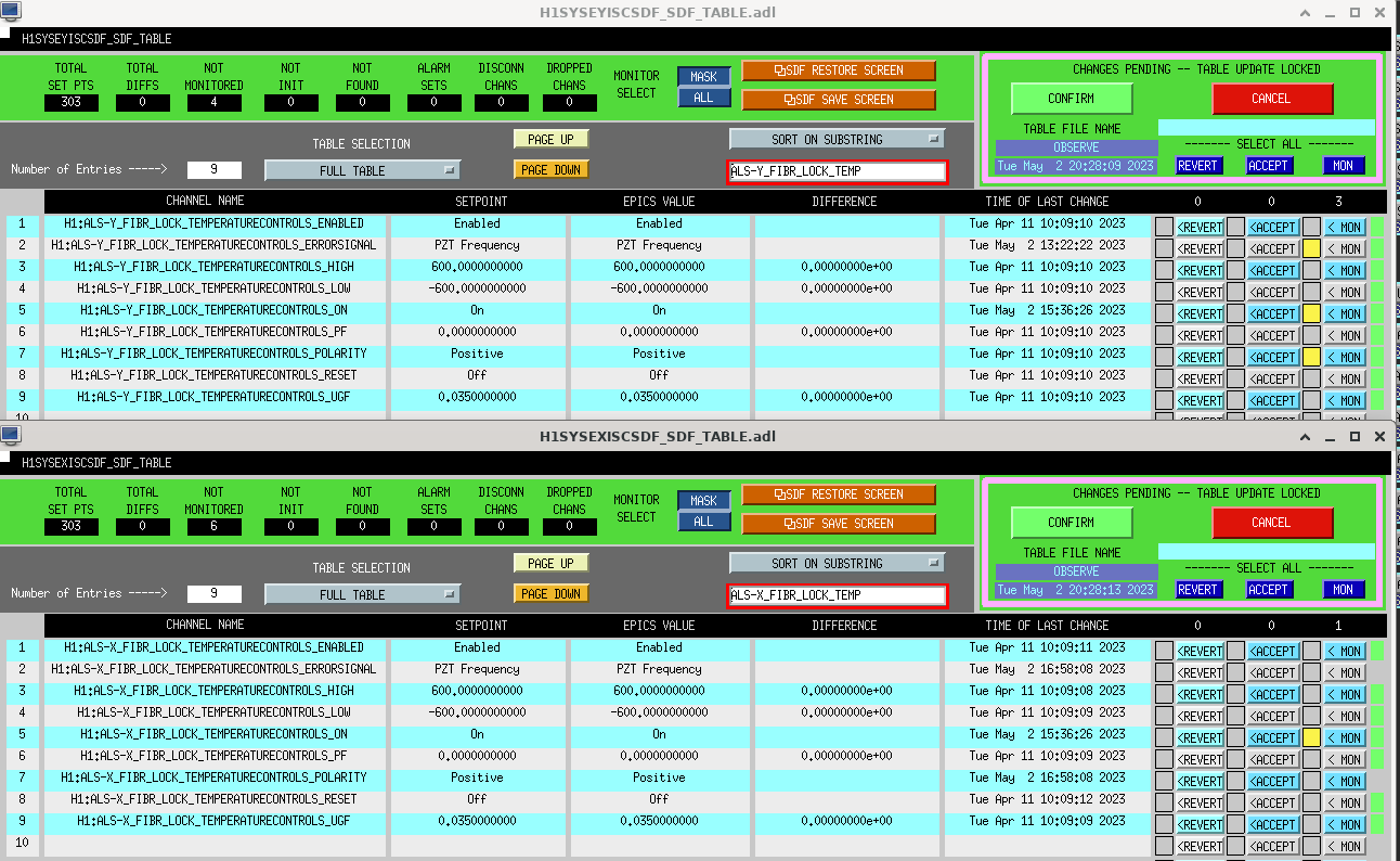
H1:ALS-Y_FIBR_SERVO_IN1GAIN and H1:ALS-X_FIBR_SERVO_IN1GAIN were already unmonitored.
Been in NLN/NLN_CAL_MEAS for 2 hours. Currently Jennie W is taking some DARM spring thermalization measurements and Vicky is adjusting Squeezing.
This is our seconds lock after Tuesday maintenance as we lost lock at 00:15UTC 1367108148, no clear reason why.
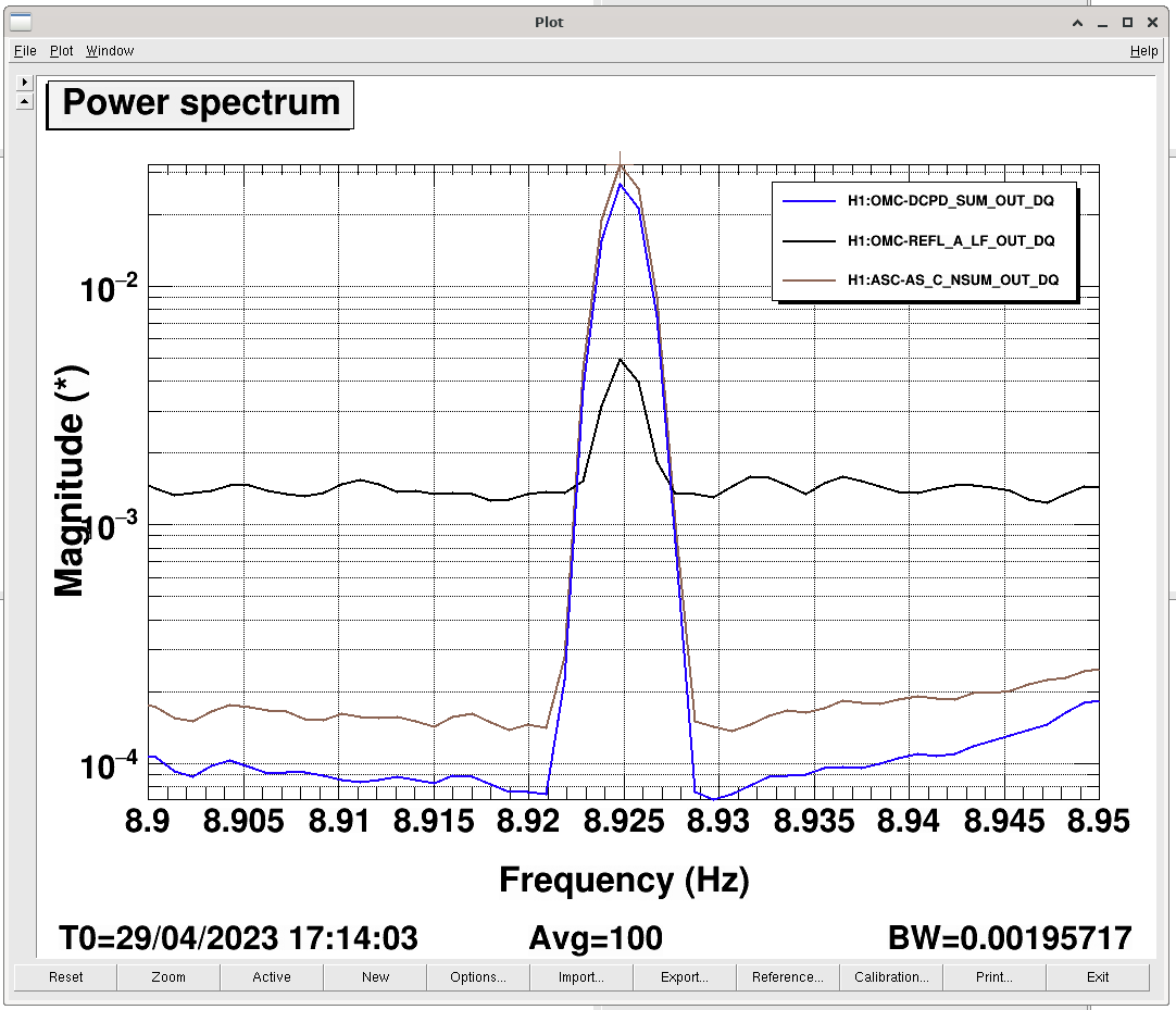
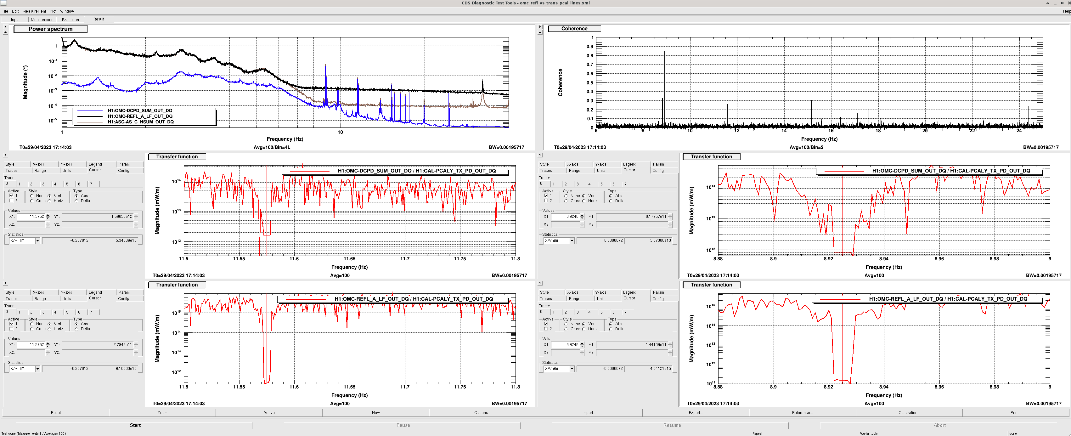
As we've got some large low frequency PCAL lines I had a look again at the how much of these lines appeared in OMC REFL and the DCPD to estimate of how much DARM signal is being rejected by the OMC, whether this is from alignment+mode-matching who knows.
The ratio of transfer functions [REFL/PCAL] / [DCPD/PCAL] at 8.925 Hz and 11.575 Hz are both about 16-17%. The 8.925Hz line has a coherence of about 0.9 and 11.575 Hz 0.7 with H1:OMC-REFL_A_LF_OUT_DQ.
Late last year we also tried putting a 1Hz line in DARM and looking at the its ratio in AS_C and REFL (after rescaling REFL and AS_C to overlap the noise spectra). Back then we found REFL/AS_C ~ 24%. Quickly doing the same for the 8.925 Hz line we also see 15% in reflection.
These numbers are not so far away from what's needed to explain a good chunk of the mystery readout losses perhaps - 68912
The main uncertainty here I think is in what local oscillator field is the DARM signal beating with at OMC REFL, is it just beating with higher order mode junk light that amplifies how much we think is being reflected? If you believe the modulation depth tests (most recent one just before the ER) then 30% of the light at AS_C (calibrated as power going into HAM6) is carrier light... There is about 830mW in total going into HAM6 so 250mW of that is carrier. Only around 20mW of that is TEM00 light that transmits through the OMC on to the DCPDs, leaving 230mW of higher order junk at OMC REFL. Which is a lot of junk light to be suspicious of. It's unclear at the moment how much of this would overlap with the DARM signal rejected from the OMC but perhaps not unreasonable to assume there is some.
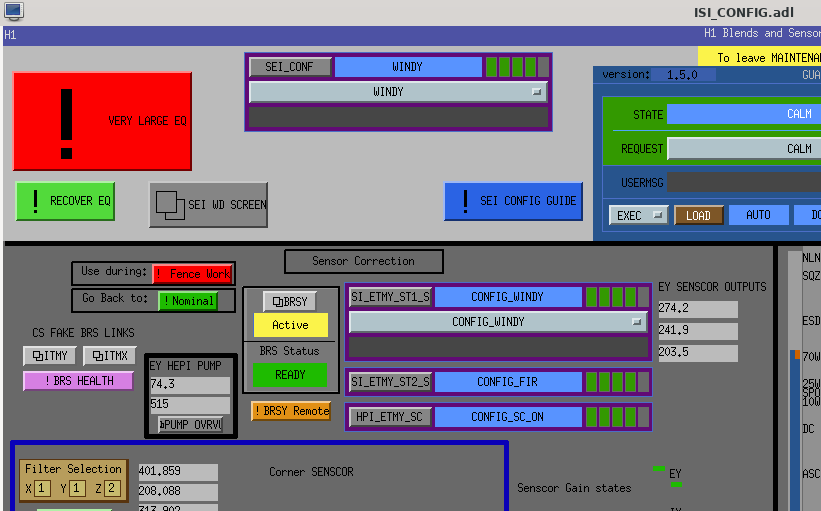
I've added 2 buttons to the ISI_CONFIG screen to manage the sensor correction during the fence work. Under the SEI WD SCREEN button there is a red button that says "Fence Work" and a green button that says "Nominal". The red button pauses the EY St1 senscor guardian, switches the filter I posted in 69162 and takes the BRSY out of the earthquake mode. The green button reverts all that.
So, before Mitch and Randy head to EY operators should hit the "Fence Work" button. When they are done for the day, revert with the green button. Hopefully we can get rid of these transitions in a couple weeks.
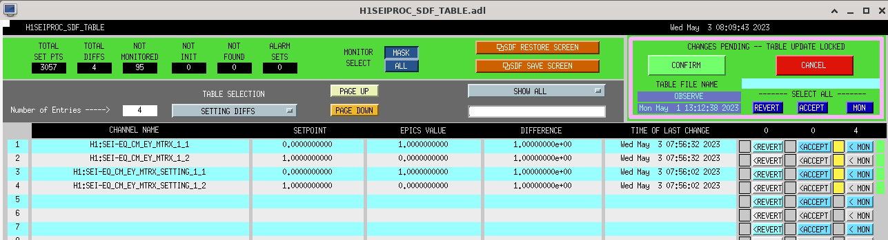
I hit the Wind Fence button this morning. This dropped us out of OBSERVING due to SEI channel values changing seen by SDF.
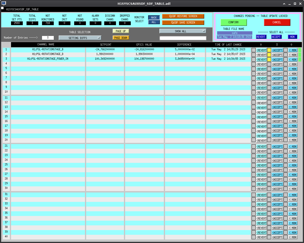
Since this is a temporary situation (repairing the wind fence), to get us back into OBSERVING, had us STOP MONITORING the (4) involved channels (see screenshot).
See LHO:69608 for a description of what's happening when this button is button is pushed.
Naoki Vicky Daniel
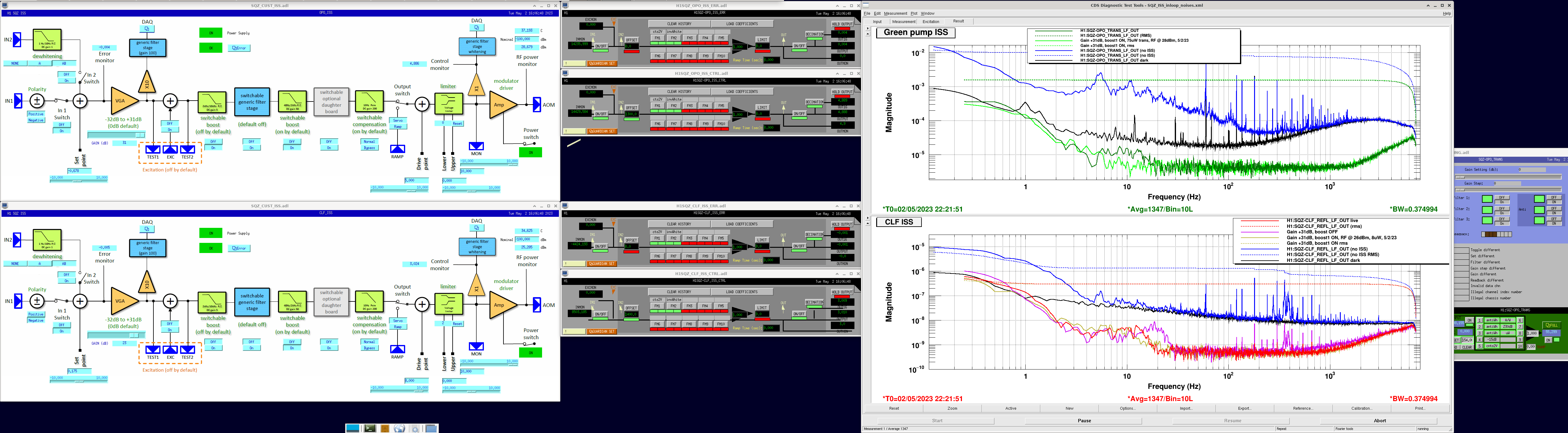
We measured and adjusted the ugf of the CLF and OPO ISS servos. Both were set to ~10kHz. The CLF cannot run with the 2kHz/10kHz boost, since the phase decays significantly faster.
Plot 1: open loop TF (solid line CLF, dashed OPO)
Plot 2: Noise at OUT1 (top OPO, bottom CLF)
With these settings none of the error readbacks are saturated.
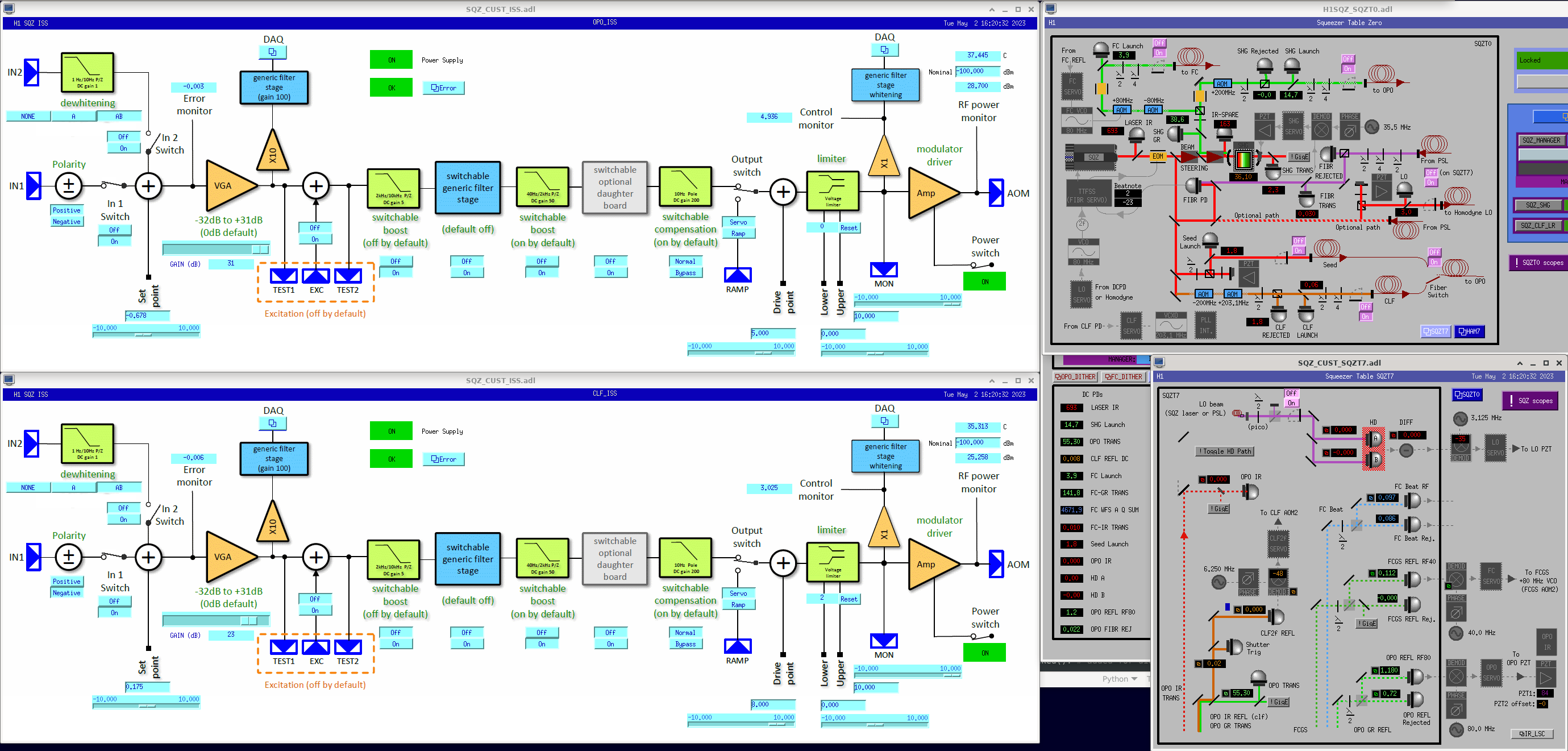
The CTRL signal DAQ readbacks for OPO + CLF ISS look great after today's chassis replacements, LHO:69232. SQZ-{OPO,CLF}_ISS_CTRL_OUTPUT's match the slow readbacks well. And, at our current ISS settings (see screenshot), DAQ readbacks of the error signal (SQZ-{OPO,CLF}_ISS_ERRORMON) are not saturated. OPO/CLF ISS settings have been updated in their respective guardians. OPO_TRANS_DC now uses all 3 whitening stages (up from 2).
DTT ISS in-loop noise template saved in $(userapps)/sqz/h1/Templates/dtt/SQZ_ISS_inloop_noises.xml . If we change OPO_TRANS power (to change gen sqz level), or change CLF power, we can run this template to ensure ISS works as expected.
Error point spectra
J. Kissel As we re-learned last Friday (LHO:69175), the coherence-based uncertainty estimate on the calibration-line-to-DARM_ERR transfer functions depends on the choice of the "Number of Averages" BUFFER_SIZE variables, and one can't independently change the DEMOD low-pass filters because their corner frequency (say, 0.1 Hz) should be kept in direct correspondence with the "FFT LENGTH" COH_STRIDE variables. As of this morning's model changes (described in LHO:69226), we now have split out the BUFFSIZE (Navgs) and COH_STRIDE (FFT LENGTH) from a single set of values for the entire collection of calibration lines, to having an independent set of numbers for each line. As a part of filling out these new values, I've performed two of the actions from LHO:69175, - Revert all DEMOD the band-passes to have a pass band that's +/- 0.1 Hz wide (what we had in O3) >> except for the 410.3 Hz line, processed by the PCAL_LINE2 demod -- see below - Revert all DEMOD I & Q low passes to a 10 second time constant, or 0.1 Hz corner frequency The PCAL team as still trying to suck the last bit of juice out of having a PCALX calibration line within 0.1 Hz of the 410.3 Hz PCALY line. The narrow band pass is necessary while the PCALX line is so close at 410.2 Hz, because of now-known contamination of the optical gain and cavity pole frequency "TDCFs" LHO:68479. So we can't revert this just yet. At least for now, we can independently set the Navgs and FFT length appropriately. As such, for the 410.3 Hz, PCAL_LINE2 infrastructure, we're still using - the NBP410.3, with +/-0.03 Hz wide band pass - the LP40s I & Q lowpass filters with a corner frequency of 0.025 Hz - the now independent N Averages of 3, (H1:CAL-CS_TDEP_PCAL_LINE2_COH_BUFFSIZE = 3) - the now independent FFT length of 40 seconds, (H1:CAL-CS_TDEP_PCAL_LINE2_COH_STRIDE = 40) All the changes have been accepted in the SDF system. The reversion process was easy with a little bit of command line BASH code (after confirming that there are LP10s in FM1 of all the DEMOD banks): $ export ACT=PCAL; export LINE=LINE1; \ caput ${IFO}:CAL-CS_TDEP_${ACT}_${LINE}_COH_BUFFSIZE 13; \ caput ${IFO}:CAL-CS_TDEP_${ACT}_${LINE}_COH_STRIDE 10; \ caput ${IFO}:CAL-CS_TDEP_${ACT}_${LINE}_GRM_MDN_ARRAYSIZE 2049; \ caput ${IFO}:CAL-CS_TDEP_${ACT}_${LINE}_GRM_AVG_ARRAYSIZE 160; \ caput ${IFO}:CAL-CS_TDEP_${ACT}_${LINE}_GRM_STRIDE_SEC 0.0625; \ caput ${IFO}:CAL-CS_TDEP_${ACT}_${LINE}_SUB_UNC_THRESH 0.09; \ z switch ${IFO}:CAL-CS_TDEP_${ACT}_${LINE}_${ACT}_DEMOD_I FM1 ON; \ z switch ${IFO}:CAL-CS_TDEP_${ACT}_${LINE}_${ACT}_DEMOD_Q FM1 ON; \ z switch ${IFO}:CAL-CS_TDEP_${ACT}_${LINE}_${ACT}_DEMOD_I FM2 OFF; \ z switch ${IFO}:CAL-CS_TDEP_${ACT}_${LINE}_${ACT}_DEMOD_Q FM2 OFF; \ z switch ${IFO}:CAL-CS_TDEP_${ACT}_${LINE}_ERR_DEMOD_I FM1 ON; \ z switch ${IFO}:CAL-CS_TDEP_${ACT}_${LINE}_ERR_DEMOD_Q FM1 ON; \ z switch ${IFO}:CAL-CS_TDEP_${ACT}_${LINE}_ERR_DEMOD_I FM2 OFF; \ z switch ${IFO}:CAL-CS_TDEP_${ACT}_${LINE}_ERR_DEMOD_Q FM2 OFF; \ z switch ${IFO}:CAL-CS_TDEP_${ACT}_${LINE}_EXT_DEMOD_I FM1 ON; \ z switch ${IFO}:CAL-CS_TDEP_${ACT}_${LINE}_EXT_DEMOD_Q FM1 ON; \ z switch ${IFO}:CAL-CS_TDEP_${ACT}_${LINE}_EXT_DEMOD_I FM2 OFF; \ z switch ${IFO}:CAL-CS_TDEP_${ACT}_${LINE}_EXT_DEMOD_Q FM2 OFF; where to move on to the next demod, I up-arrowed, and made "ACT" either PCAL or SUS, and changed "LINE" to go from LINE1 through LINE10.
TITLE: 05/02 Day Shift: 15:00-23:00 UTC (08:00-16:00 PST), all times posted in UTC
STATE of H1: Preventive Maintenance
SHIFT SUMMARY:
Fairly light Maintenance. Did have some issues with the BSC1 SEI power supply swap (IO Chassis needed to be swapped instead of what was planned and an additional power supply in rack was swapped as well). Handing over H1 to Camilla as we get to MAX POWER for Elenna to do checks on the laser after today's PSL work.
LOG:
TITLE: 05/02 Eve Shift: 23:00-07:00 UTC (16:00-00:00 PST), all times posted in UTC
STATE of H1: Preventive Maintenance
CURRENT ENVIRONMENT:
SEI_ENV state: CALM
Wind: 11mph Gusts, 8mph 5min avg
Primary useism: 0.02 μm/s
Secondary useism: 0.17 μm/s
QUICK SUMMARY: Currently IFO is re-locking after Tuesday Maintenance. Currently at POWER_10W and will hold at MAX_POWER to check PSL power is as expected after ISS AOM realignement: alog 69259.
SUS, SEI, CDS, VAC okay
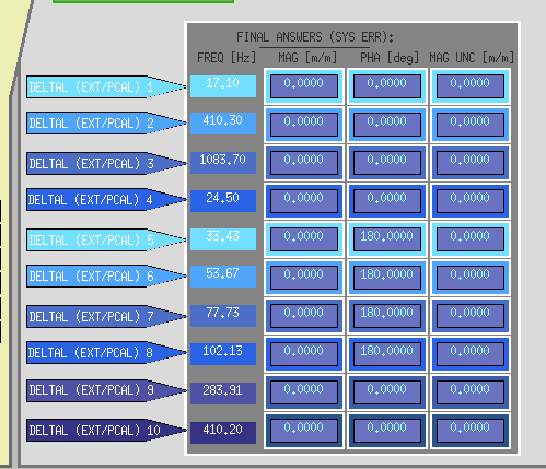
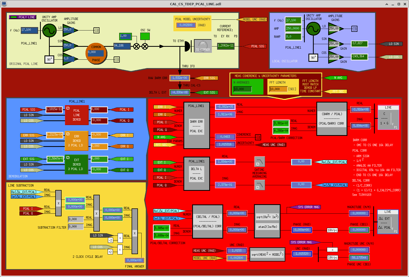
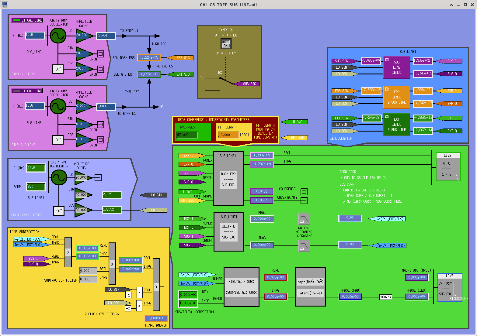
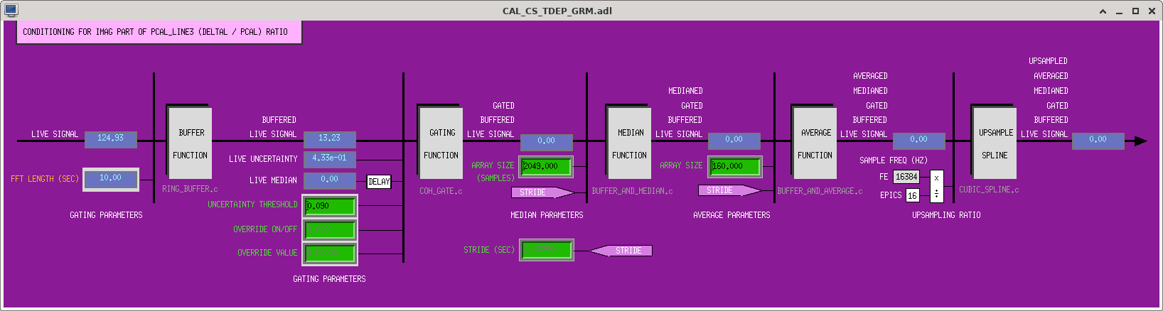
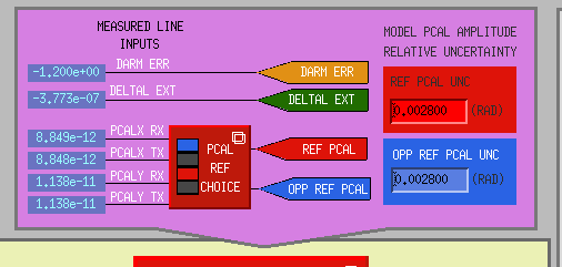
J. Kissel ECR E2300125 IIET Ticket 27801 WP 11166 In support of the model changes that were prepped yesterday (LHO:69226) and installed today (LHO:69251), I've updated the MEDM screens /opt/rtcds/userapps/release/cal/common/medm/ CAL_CS_TDEP_OVERVIEW.adl CAL_CS_TDEP_OPPREF_PCAL_DEMOD_OVERVIEW.adl CAL_CS_TDEP_REF_PCAL_DEMOD_OVERVIEW.adl CAL_CS_TDEP_SUS_ACT_DEMOD_OVERVIEW.adl CAL_CS_TDEP_PCAL_LINE.adl CAL_CS_TDEP_SUS_LINE.adl and committed them to the svn. See attached screenshots of the new screens. You'll maybe gather a better understanding of what's changed if you head to the model prep aLOG, LHO:69226, but in short: - (5th shot) There's now two new EPICs records that house the modeled amplitude uncertainty for the PCAL (e.g. I've now installed 0.0028 for "0.28% 1-sigma" reported in G2300471), Channels: H1:CAL-CS_TDEP_REF_PCAL_AMP_RELUNC and H1:CAL-CS_TDEP_OPP_REF_PCAL_AMP_RELUNC - (1st shot) The (DELTAL / PCAL) systematic error transfer function measurement shows phase in degrees now, and has an associated uncertainty. Channel Examples: H1:CAL-CS_TDEP_PCAL_LINE2_SYSERROR_MAG_MPM, H1:CAL-CS_TDEP_PCAL_LINE2_SYSERROR_PHA_DEG, and H1:CAL-CS_TDEP_PCAL_LINE2_SYSERROR_MAG_MPM_UNC. - (2nd shot) The (DELTAL / PCAL) transfer function now goes through the same gated running median (GRM) process as the subtraction output did before it gets feed into the PCAL_CORR / DELTAL_CORR complex divide. Further, there's now a quadrature sum of the modeled PCAL amplitude error and the measurement, coherence-based uncertainty and that result is converted into an uncertainty in magnitude and phase. Channel Examples: H1:CAL-CS_TDEP_PCAL_LINE3_SYSERROR_UNC_RAD, H1:CAL-CS_TDEP_PCAL_LINE3_SYSERROR_MAG_MPM_UNC, and H1:CAL-CS_TDEP_PCAL_LINE3_SYSERROR_PHA_DEG_UNC - (3rd shot) The (DELTAL / SUS) transfer function portion is now much more accurately depicted. That transfer function also now passes through a gated running median process, and has an associated answer, but no additional uncertainty beyond the coherence-based measurement uncertainty. Channel Examples: H1:CAL-CS_TDEP_SUS_LINE2_DELTALOVERSUS_MAG_RATIO and H1:CAL-CS_TDEP_SUS_LINE2_DELTALOVERSUS_PHA_DEG - (4th shot) There's now a dedicated screen for the libraried version of the gated-running-median process (noteably different in annoyingly subtle ways from the older TDCF version).
FAMIS 21120
The TCSX chiller ruler fell off again, I'll find some new stick to get it to stay on, but as of writing this log it was just stuck back on.
Added 250mL to both chillers, all filters and diffusers looked good.
Final ruler levels: TCSX - 30.0cm TCSY - 10.0cm
Randy, Jim, Mitchell
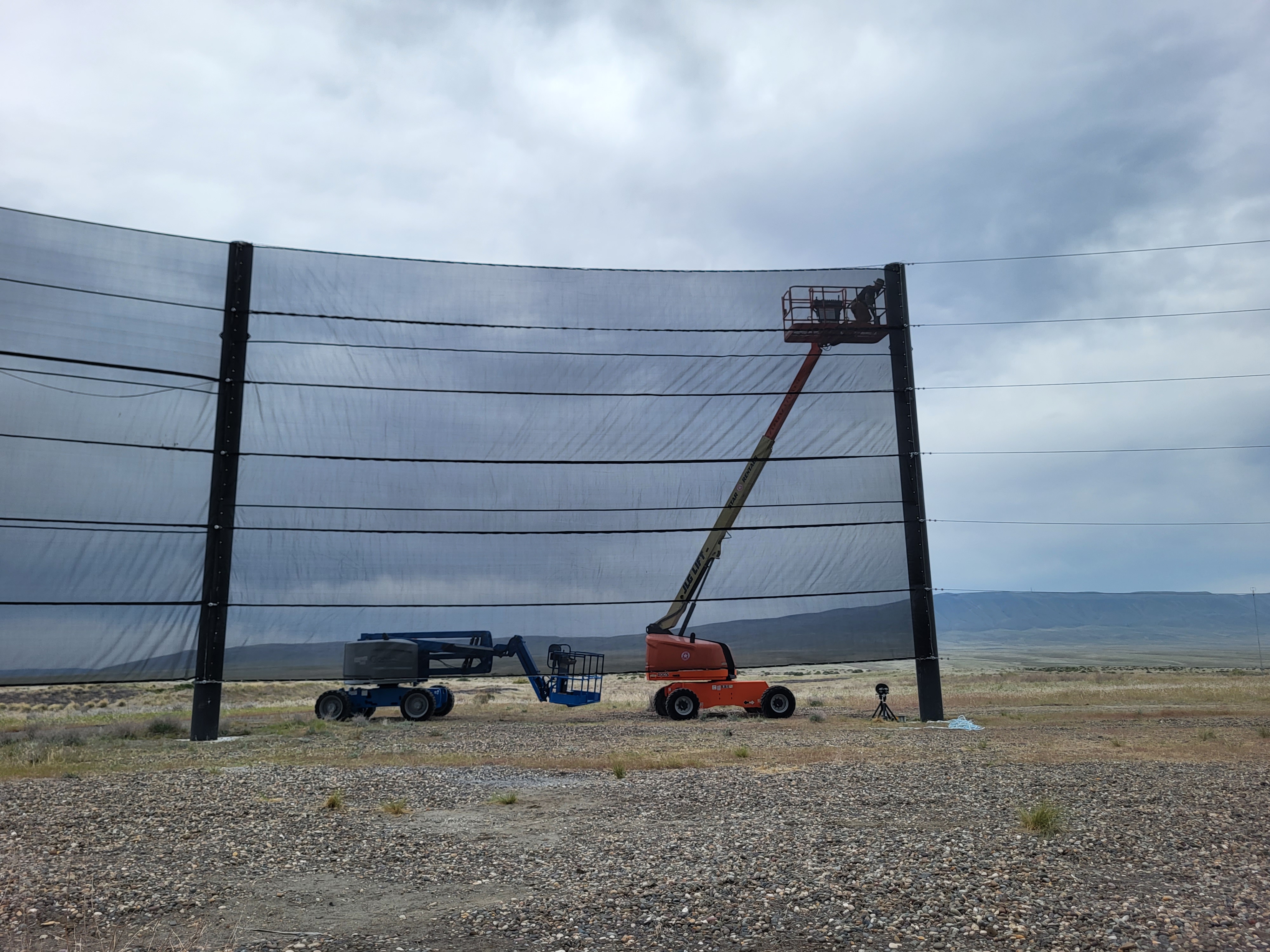
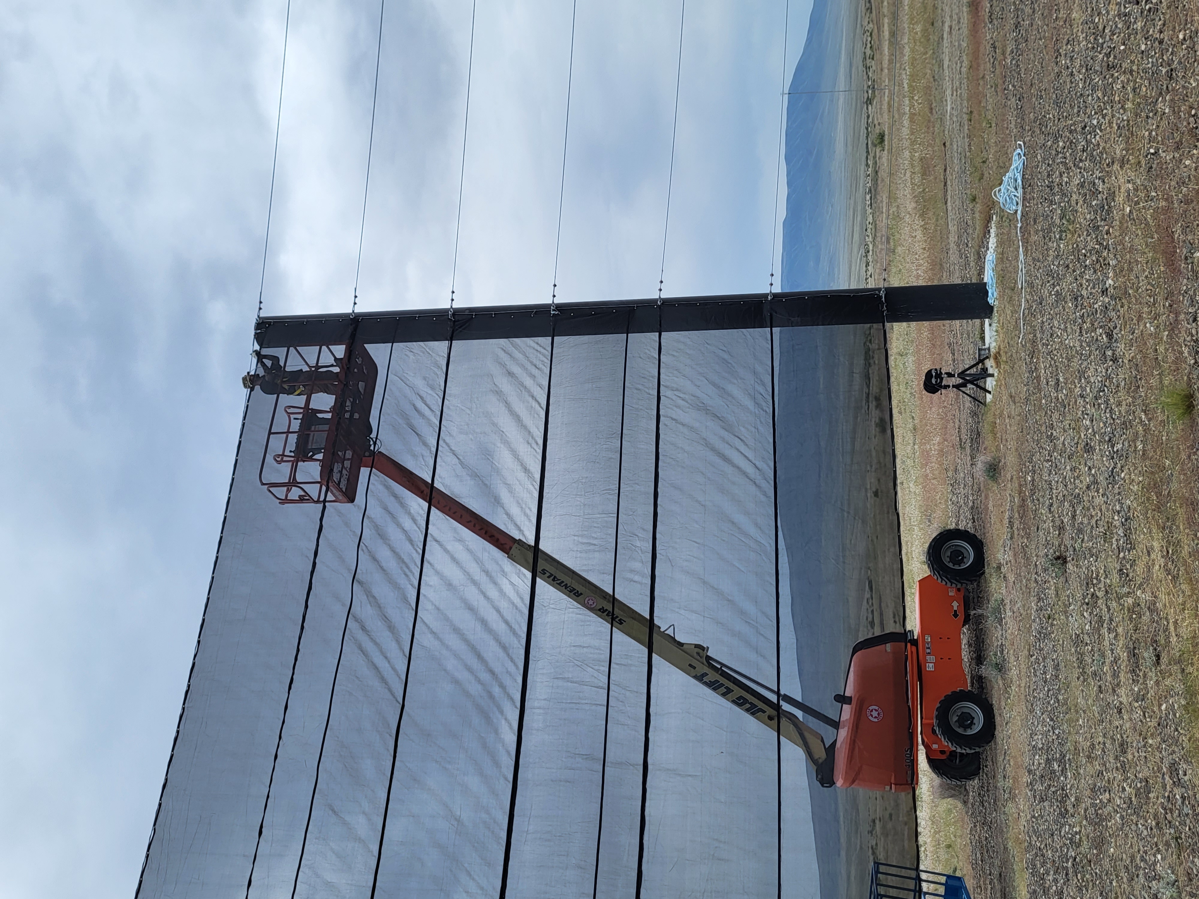
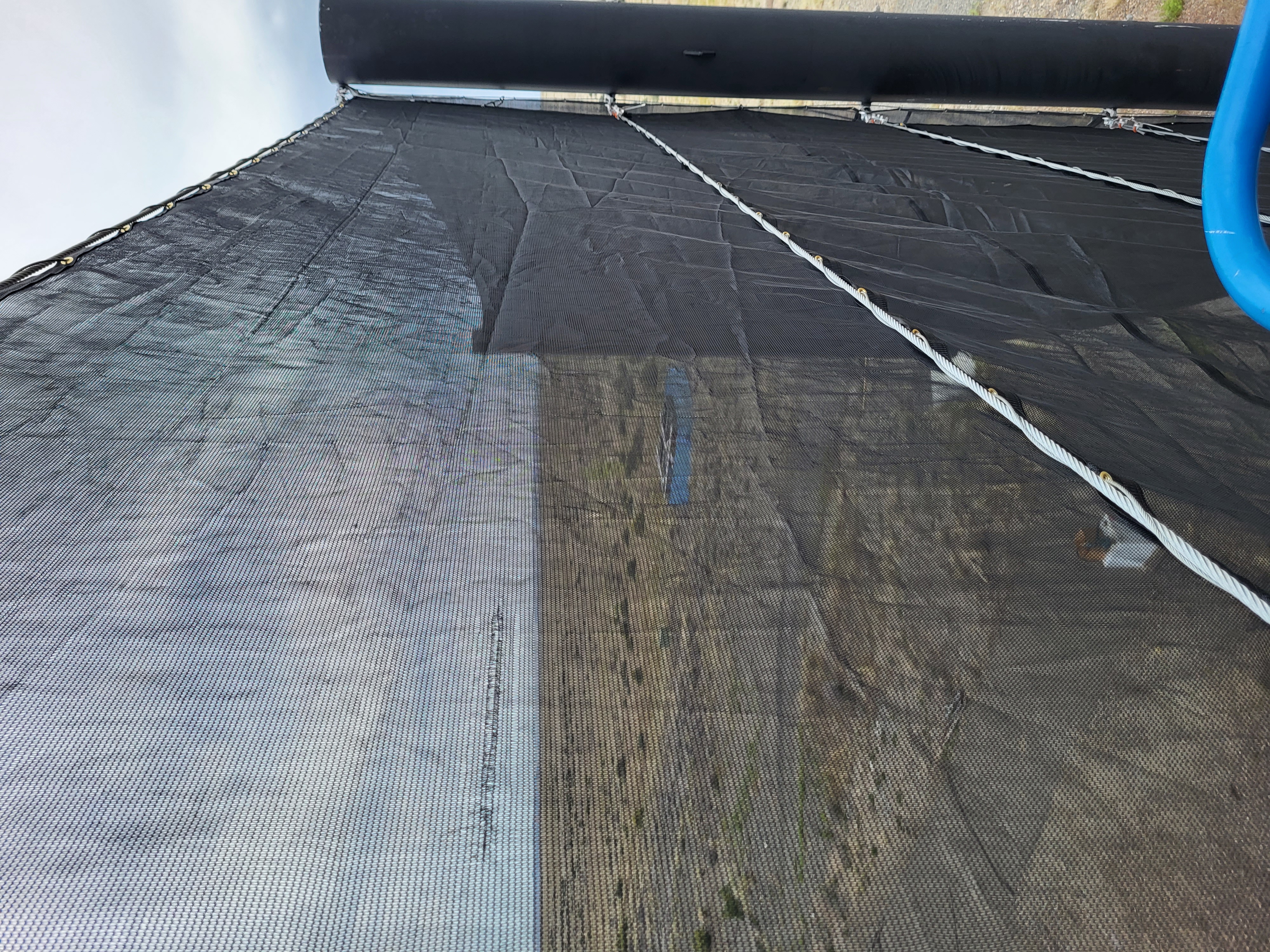
The first panel finished getting put up today. Half of the panel went up yesterday. The vertical side cables remain, the seven field runs have been completed.
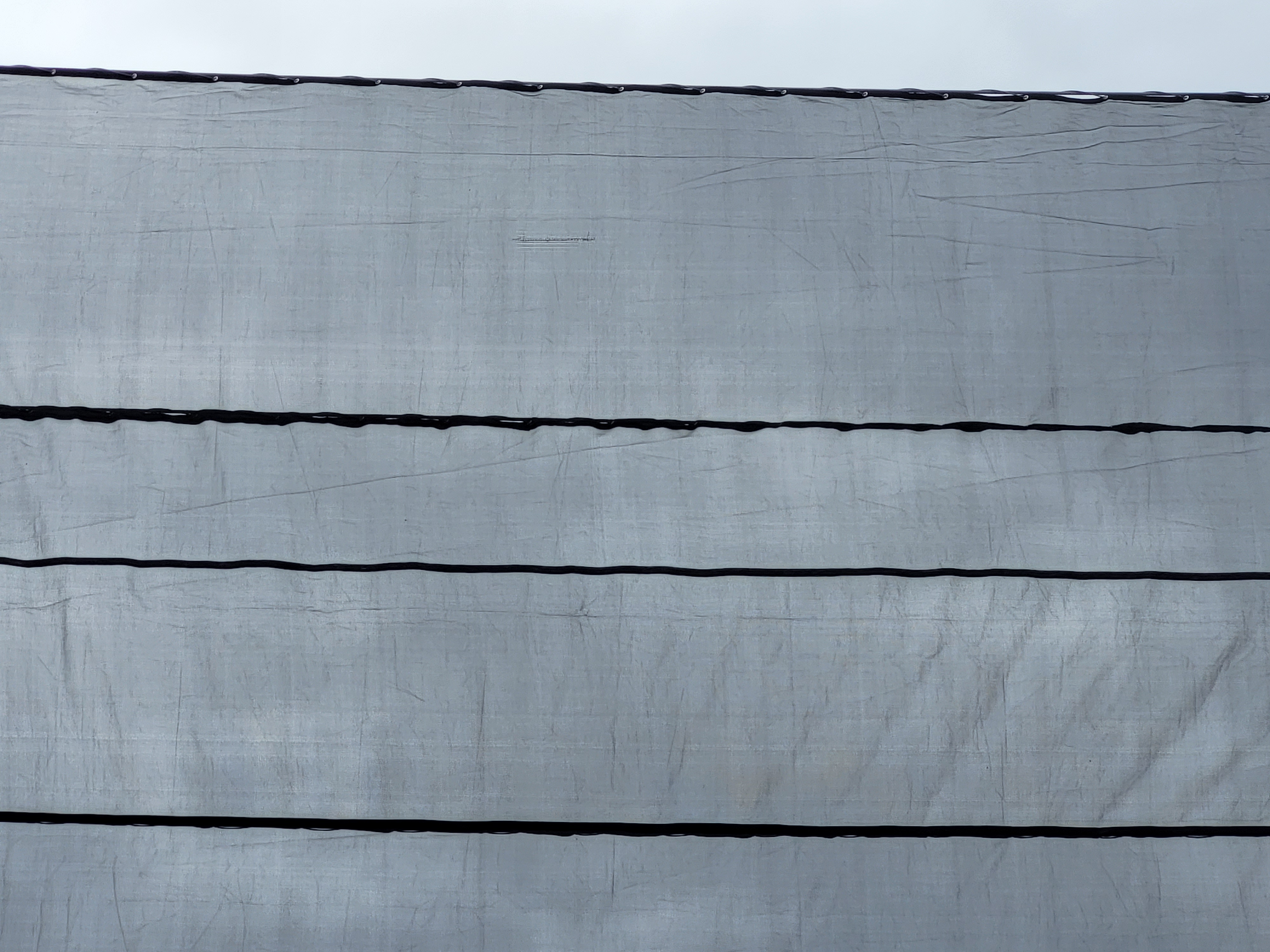
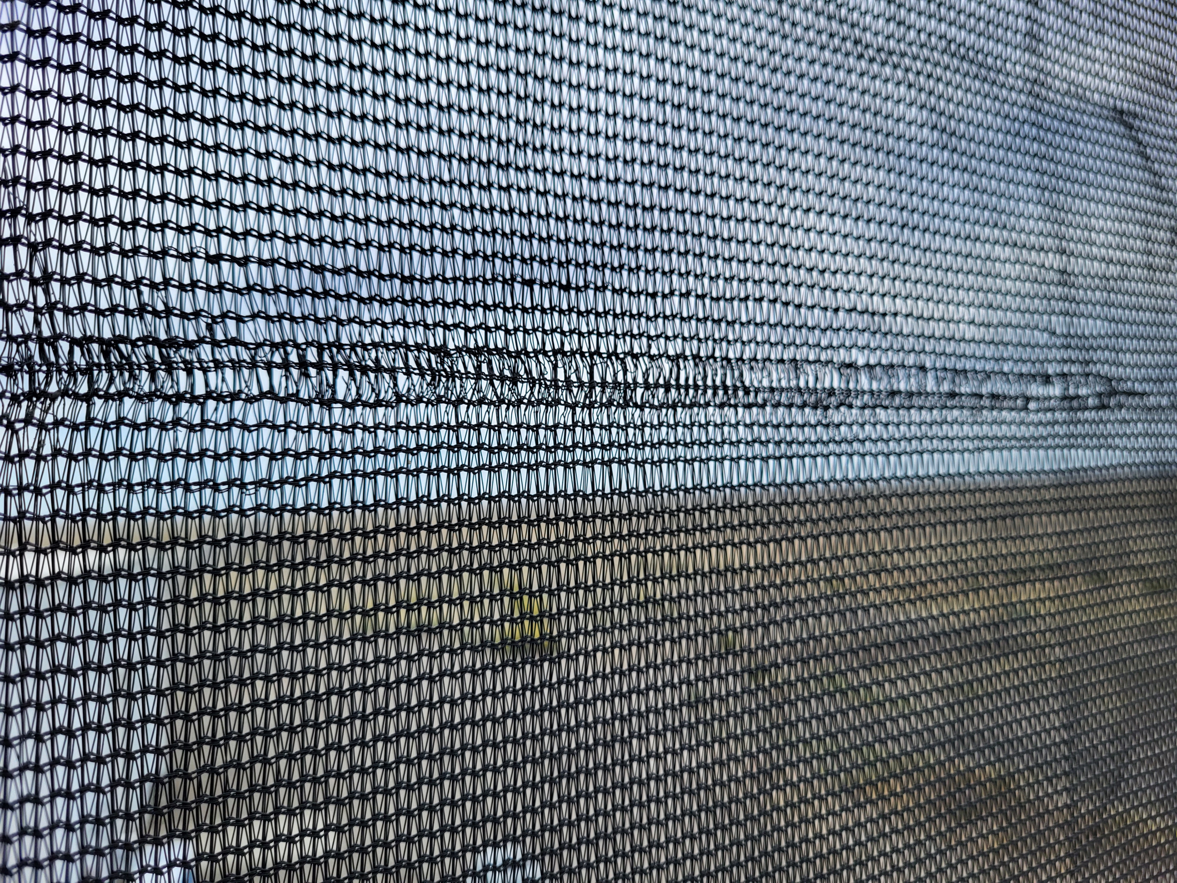
While stringing the top cable a weak area in the panel was noticed. This may or may not be an issue down the road.
Following the steps in alog 66502, I've recalibrated the PSL rotation stage. This was a good thing to do after our activities in the enclosure today (alog from Jason incoming).
| Power in (W) | D | B (Minimum power angle) | C (Minimum power) | |
| Old Values | 100.349 | 1.990 | -24.766 | 0.000 |
| New Values | 104.199 | 1.990 | -24.816 |
0.000 |
EDIT: Forgot to attach the relevant plot, text file, and accepted SDF diffs table.
J. Oberling, R. Short
Today we went in to primarily measure the beam powers between Amp2 and the PMC to ensure everything adds up (make sure we know what power is being lost where and is as expected), and to fix that stubborn EOM_Out calibration error. It turned into a realignment of the ISS AOM and re-calibration of the ISS diffracted power percentage.
To start, we measured powers between the PMC output and the IOO EOM:
This mostly holds together, we had to use 2 different power meters due to space constraints (the big 300W water-cooled power meter for PMC Trans and EOM Trans, a smaller 10W power meter for the ALS and PBS rejected beam).
Next we measured the powers between Amp2 and the PMC:
We weren't able to get a power meter in to measure the 2nd rejected beam from the high-power attenuator (HPA). The HPA consists of a HWP and 2 crossed thin-film polarizers (TFP) to provide power control and polarization cleanup; we could measure the beam rejected from the 1st TFP but could not fit a meter in to measure the 2nd. As can be seen, we can't account for 7.8W of power between Amp2 and the PMC. No clue where it could be, there are no beams of that strength in the area that we could find with either IR cards or an IR viewer; no stray beams, no leakage beams, everything looks as it should. Now, in looking for this extra power, we noticed the ISS AOM was misaligned (hence the !!!!! after the ISS AOM power measurement). When we set the ISS up we had ~4.4W in the 1st order diffracted beam with an ISS Offset slider value of 5; with that same offset slider value we now have 6.3W. So we realigned the ISS AOM.
We used the HPA to drop the power through the ISS down to about 0.5 W and installed the AOM cover (which has rough alignment apertures on it), and sure enought, the alignment was off. We roughly aligned the ISS AOM, then went back to full power through the HPA and went about finding the diffracted beams again. With a slider value of 5, we slightly tweaked the AOM angle (moving clockwise) until we had ~4.4 W in the 1st order diffracted beam, returning it to where it was when we set the ISS up at the end of the laser upgrade. The other diffracted beam (the -1 order) was barely visible as it should be (can't entirely get rid of it, and no there are not multiple watts hiding there). We then took the data needed to check the Diffracted Power % calibration on the ISS MEDM screen. This uses the AOM drive voltage and the power in the 1st order diffracted beam to calibrate the graph. That done we set the ISS Offset slider back to its original value of 5 and measured the power input to the PMC at 127.9 W. Now we are only "missing" ~5W, so we did recover a couple as expected with the ISS AOM realignment. Still can't find where that 5W is, however.
After recovering and tweaking the PMC (ISS AOM realignment changes beam alignment into the PMC), we had 108.9W transmitted and 16.3W reflected. At this point we were already ~30 minutes past the maintenance window, so we did not tweak the PMC mode matching as we were hoping to do. We recalibrated the PMC Trans, PMC Refl, Amp2 Out, and EOM Out PDs based on our measurements, and left the enclosure.
Once back in the control room we relocked the PMC and tweaked its beam alignment for a final time (get better results with the enclosure environment controls OFF), and ended up with ~110.2W output. Oddly enough, after re-calibrating the EOM Out PD and seeing it read less than the PMC Trans (as it should), once we left the enclosure and tweaked the PMC alignment it's back to reading higher than PMC Trans. *sigh* It only reads a couple tenths of a watt higher, not several watts, but it's still reading higher. So we're going to have to go back in at some point and measure the EOM out again and recalibrate that PD, again. Ugh. When we go back in to do the EOM Out calibration measurement, I also want to try to fit a power meter in to measure the 2nd rejected beam from the HPA, and continue the search for this 5W we can't seem to find.
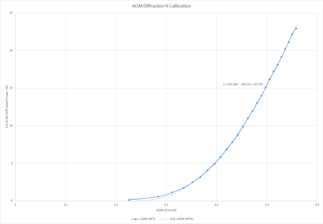
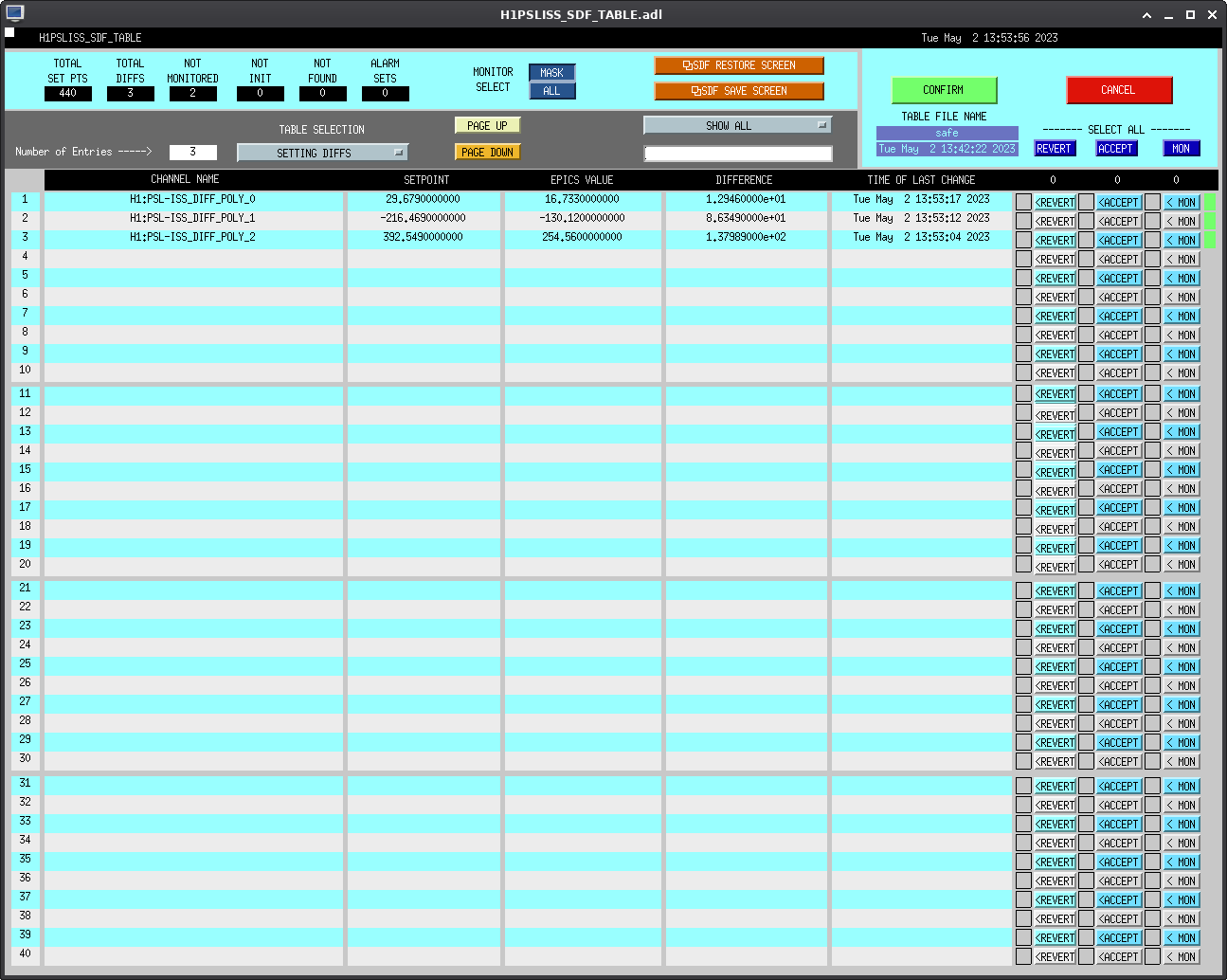
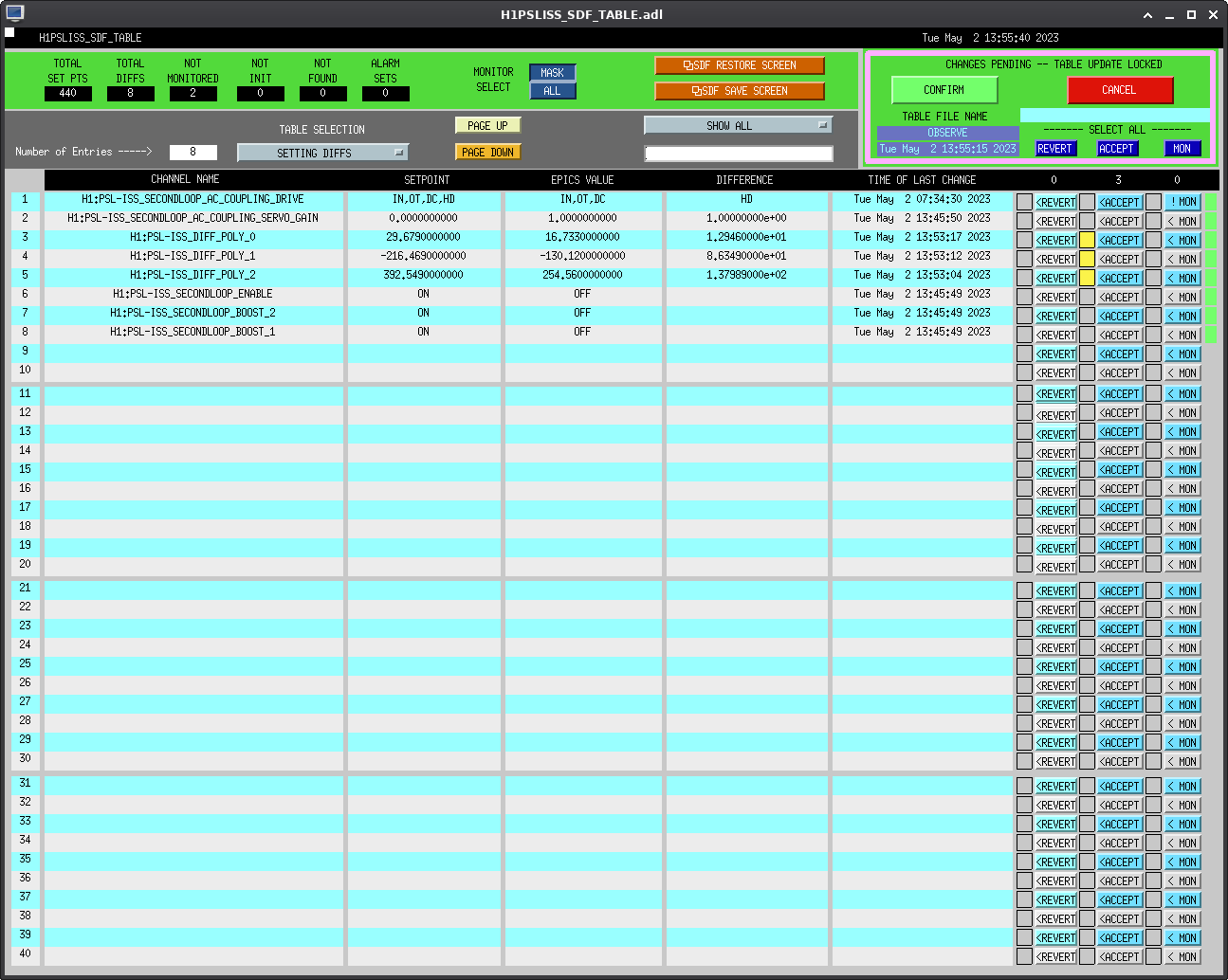
Finally, we re-locked the FSS RefCav and tweaked the beam alignment into it, improving the TPD from ~0.78V to ~0.94V. I then performed the 2nd-order polynomial fit to the ISS AOM diffracted % data we took, and updated the polynomial (see attached picture); new values are: 254.56x^2 - 130.12x + 16.733.
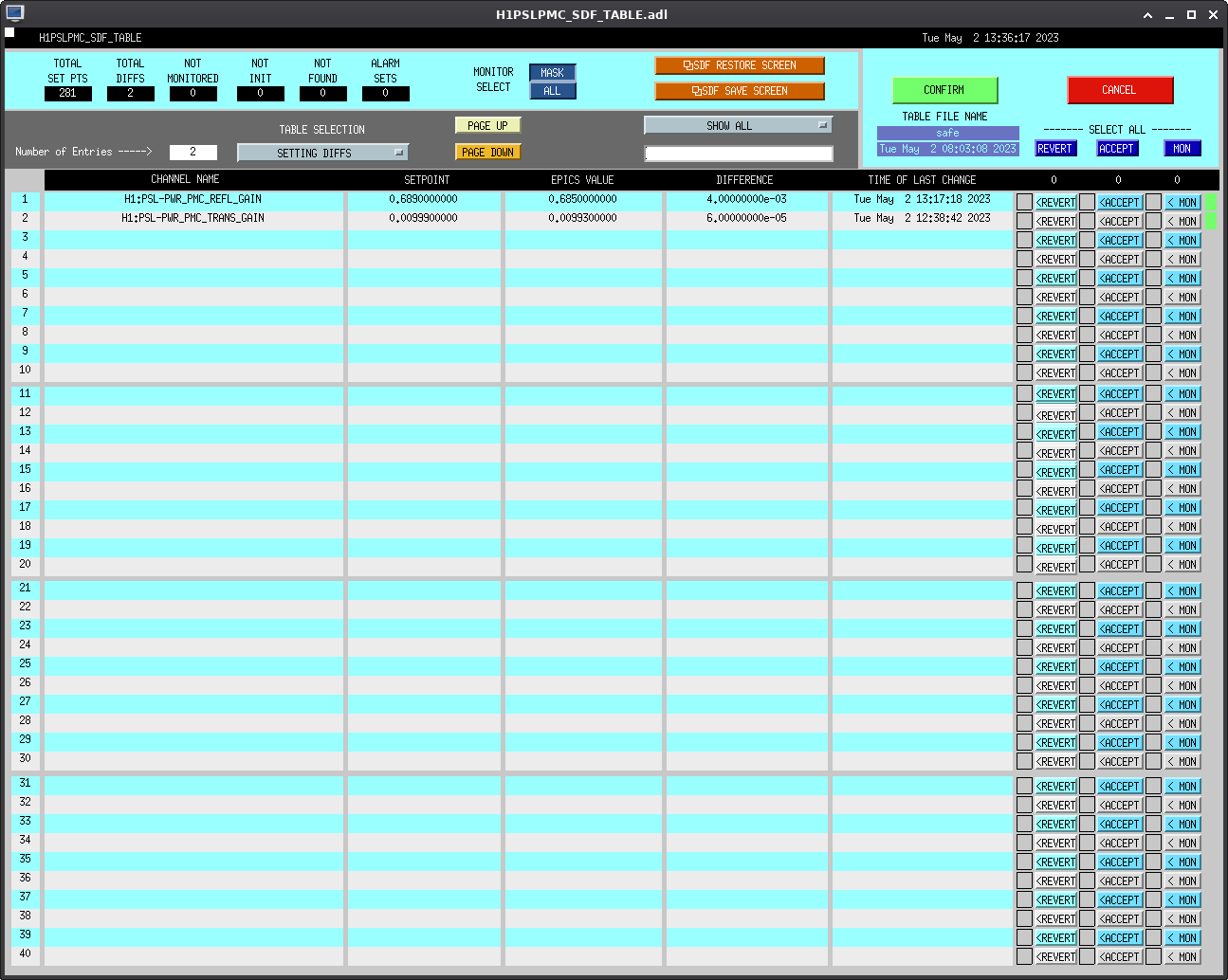
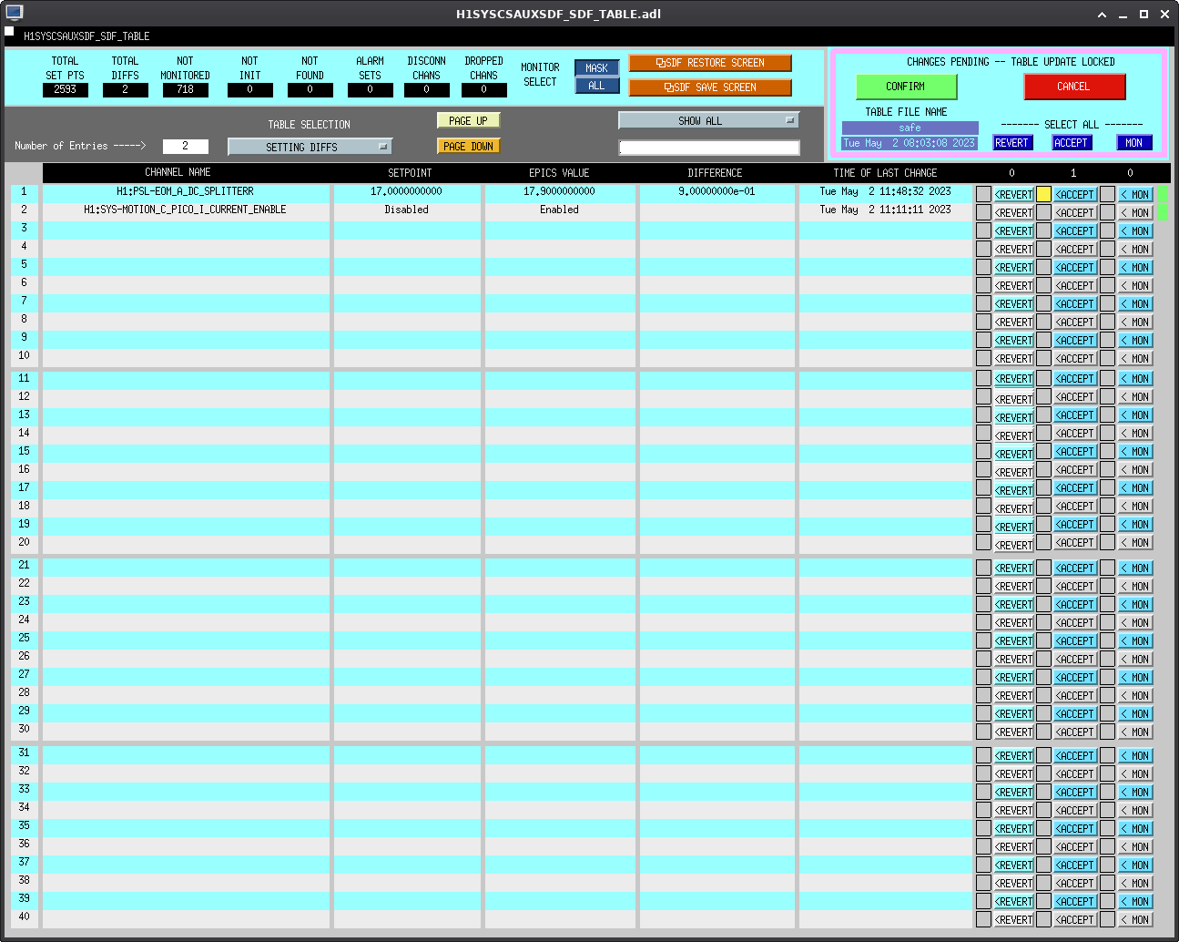
Several SDF diffs were created and accepted, in both Safe and Observe. Ryan has screenshots of those that he will attach as a comment to this alog. Since we still have a few things to check on (like the EOM Out cal *sigh*), I'll keep WP 11164 open and we'll target the next maintenance window (5/9/2023) to get this wrapped up.
Yesterday, Dripta set the XY comparison correction factors to 1.0 for both the Xend and Yend Pcals.
Last night we had a good 10-hour lock stretch during which we can assess the X/Y comparison factor, chi_XY.
The attached plot shows that it is about 1.0025.
Rick Savage, Dripta
We finally assessed chi_XY over a ~ 9-hour lock stretch using a DTT template made by Rick. We set start and end frequency to 410.1Hz and 410.4Hz respectively, BW = 0.001 Hz, Overlap = 50%, and Average=10. For the start times listed below the deviation of Pcal X/Y comparison factor, chi_XY, from 1.0 was calculated by hand:
start time = 05/02/2023, 00:30 UTC --> 27.5 hundredths of a percent (hop)
start time = 05/02/2023, 01:30 UTC --> 27.5 hop
start time = 05/02/2023, 02:30 UTC --> 28.7 hop
start time = 05/02/2023, 03:30 UTC --> 27.7 hop
start time = 05/02/2023, 04:30 UTC --> 25.7 hop
start time = 05/02/2023, 05:30 UTC --> 20.3 hop
start time = 05/02/2023, 06:30 UTC --> 28.1 hop
start time = 05/02/2023, 07:30 UTC --> 30.1 hop
The mean and the standard deviation of the above values are 26.95 hop and 2.77 hop respectively.
Using this new value of chi_XY = 1.0027, we calculated the new correction factors at the X and Y-end, C_X = 1.0012 and C_Y = 1.0015. The EPICS variables for the following channels were updated accordingly,
H1:CAL-PCALX_XY_COMPARE_CORR_FACT : 0.9988 (1/C_X)
H1:CAL-PCALX_XY_COMPARE_CORR_FACT : 1.0015
These changes have been accepted in SDF.
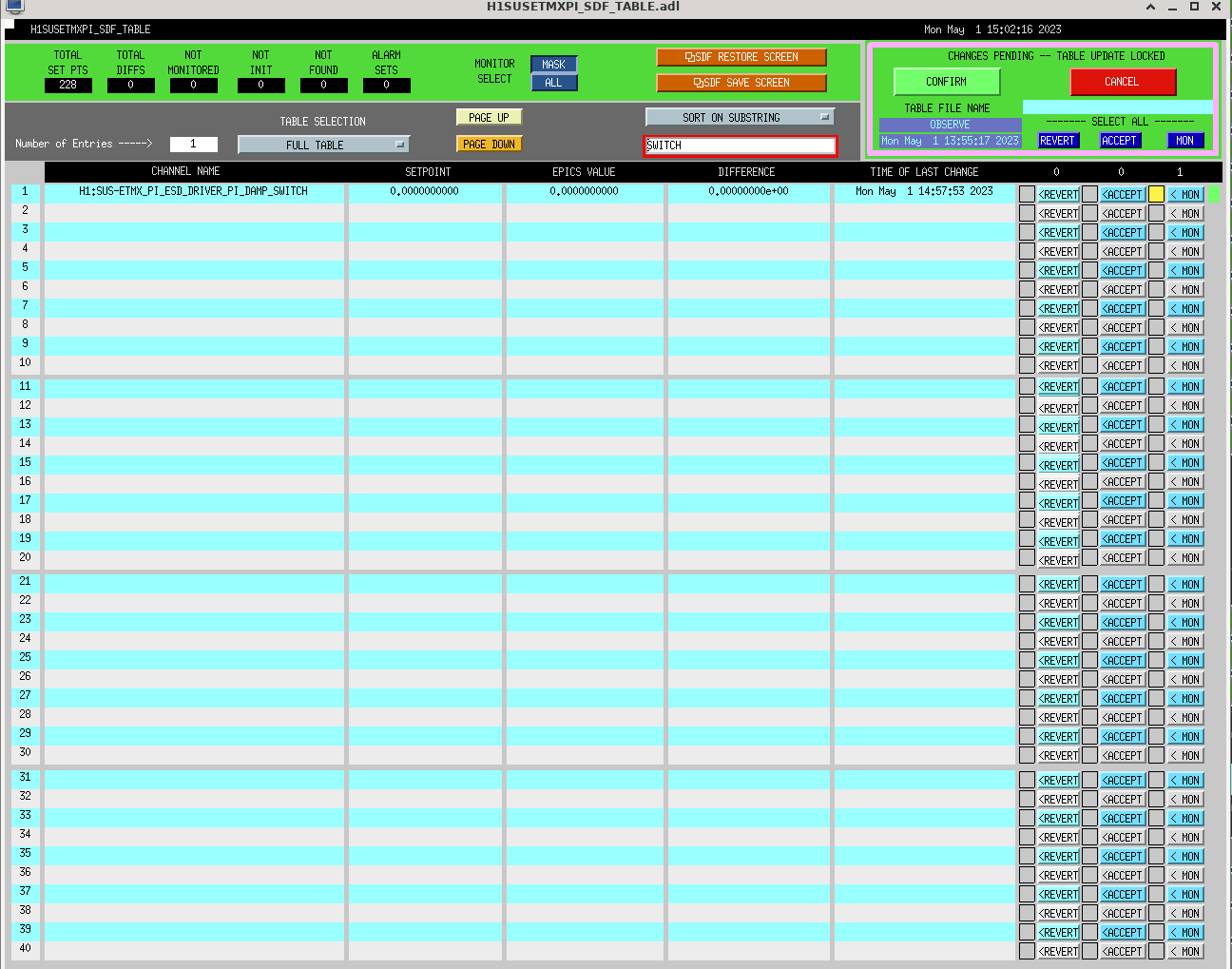
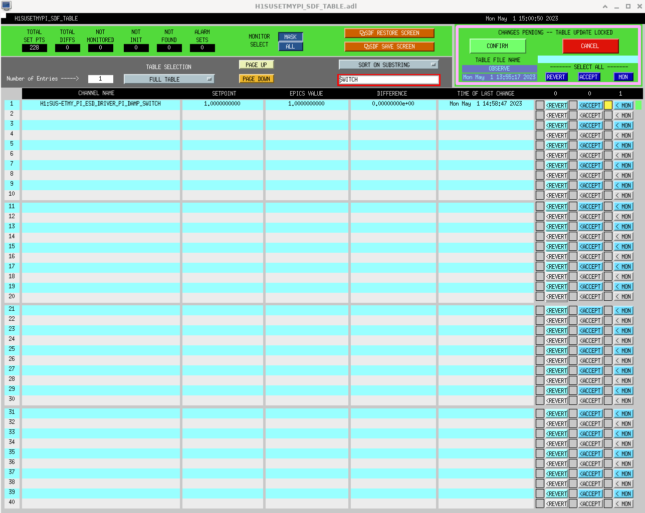
I've unmonitored the SUSETMX/YPI SWITCH channels at Vicky's request
I don't think we need PI damping most of the time now as TCS has settled, so I am minimalizing the SUS_PI guardian code to only start ESD damping if necessary. The following changes have been made to SUS_PI guardian; if all is good we can remove SUS_PI from ISC_LOCK soon.
The guardian reload kicked us out of "OBSERVING", because SUS_PI guardian was not "OK" for about 60ms as it reloaded, see trends.
Camilla, Vicky. We've increased the PI damping thresholds to: mode24 @ RMSMON = 10, mode31 @ RMSMON = 12.