[RyanS, Oli, Jenne, Jeff]
Locking went well, and we're currently at NomLowNoise (no squeezing though). We're good to go for swapping the Xend DACs tomorrow.
SRC1 during DRMI ASC seems to pull things away at the last little bit rather than converging, so we've been turning it off by hand. If it's still being problematic when we next try to lock (tomorrow? or Wed?), then we should set it to False in the DRMI guardian.
We also turned SRC1 off in full ASC during our first lock attempt, since it seemed to be wandering off. But, we lost lock in MOVE_SPOTS, probably because we weren't by-hand making the SRM follow along (since the beam diverters were closed so we didn't really have anything to track with). Second lock I left SRC1 on in full ASC, and things went fine and we got all the way to NLN.
The squeezer guardian is stuck in LOCK_OPO. I tried once setting the SQZ_MANAGER to DOWN and again to FREQ_DEP_SQZ, but it's still not happy. Since this is not what we were trying to test today (we were just seeing if the Yend DAC swaps worked), I'm just leaving the SQZ_MANAGER in DOWN.
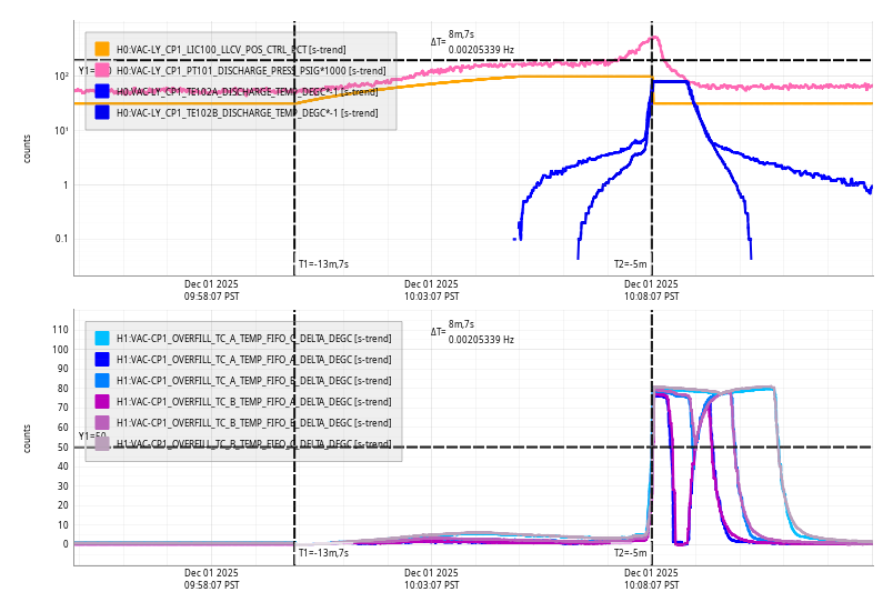
We did, at Jeff's suggestion, have the VIOLIN_DAMPING guardian paused, since we didn't want to do bad things to violin modes if there was a big phase change with the new DAC. However Daniel estimates that we should see about a 10 degree phase shift at 1kHz, and a much smaller shift at 500 Hz, so I've just unpaused that guardian and the modes seem to be damping fine.
I am leaving the IFO locked, but requested ISC_LOCK to DOWN, so that if it does lose lock, it won't try to re-lock. This, and the lack of squeezing, means that I am not setting the Observing bit.


The IFO is still locked, but I think maintenance activities can start at any time.