Betsy, Jason, Nutsinee, Alastair (on phone)
Procedure (written based on Alastair's experience at Livingston. somewhat useful): T1600050
Today we successfully flushed both TCS chillers. First we switched off the keys at the controller boxes. Then we switched off all the power supplies on the mezzanine (two TCS powers supplies, an RF oscillator, the AOM power supply was already off since the AOMs were taken out of the water system and not being used). Dave was going to turn off the OAF AI chasis anyway so we did a little test to see if turning off the AI chasis would trip the chiller right away. The result was the chillers were slowly driven to low temperature, they did not trip instantaneously.
Then we continued -- once Dave confirmed that the AI chasis has been turned off and the result was clear, we turned off the chillers and unplug the power and I/O cables, removed the chillers from the water systems (using the quick connects), then pulled chillers away from the wall (which has a power outlet, we also covered it with tape just in case). We had issue trying to drain the chillers as we followed the instruction. Opening and closing the drain plug did not let water through, we had to unscrewed and losen the drain "pipe" itself. we unscrewed the drain plug and plugged in hoses to allow water into a bucket. All these were not written in the instruction.
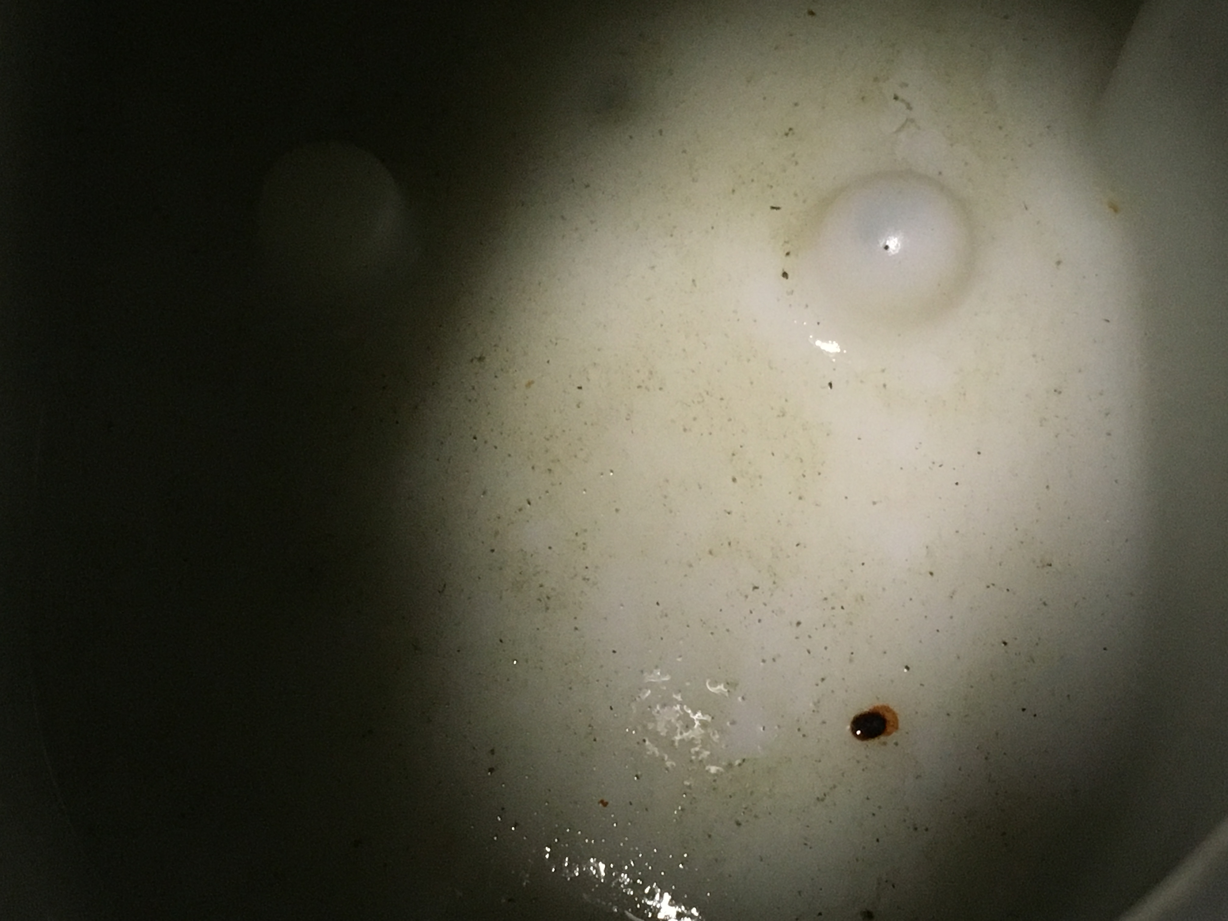
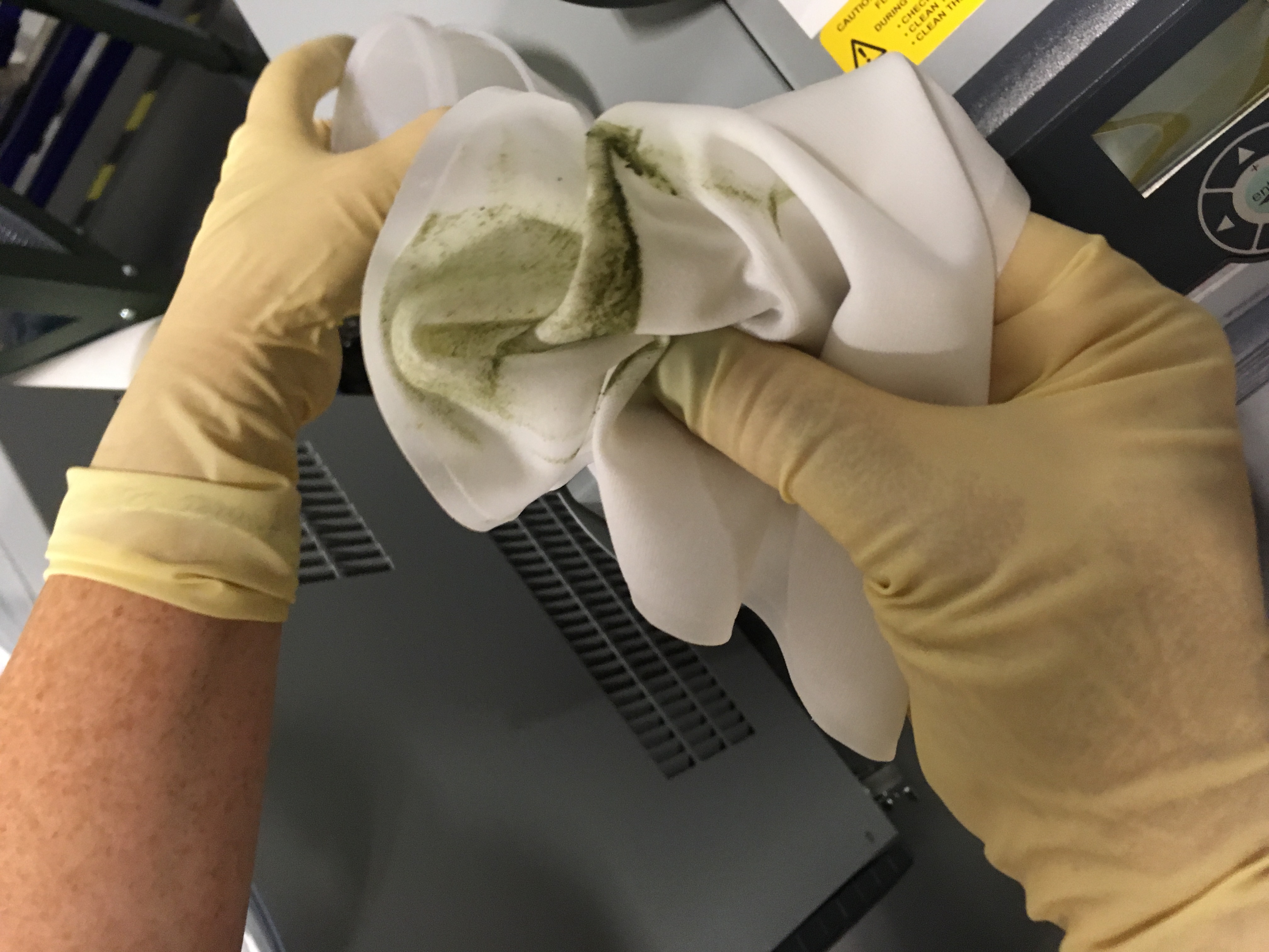
Then we noticed a lot green "stuff" sitting in the water container inside the chiller. Y chiller was worse than X chiller. We took some samples and tried our best to wipe the container clean. That red spot didn't come off by the way.
Then we reconnected the outlet pipes but left the inlet pipes disconnected. The inlet pipes had their quick connects taken out at one end pointing to the bucket. We refilled the chillers with clean lab water, plugged the power cable back in and started flushing. We didn't plug the IO cable at this point since the AI chasis were still down and I don't see a need of communicating with the front end. Plus it's just going to get in the way.
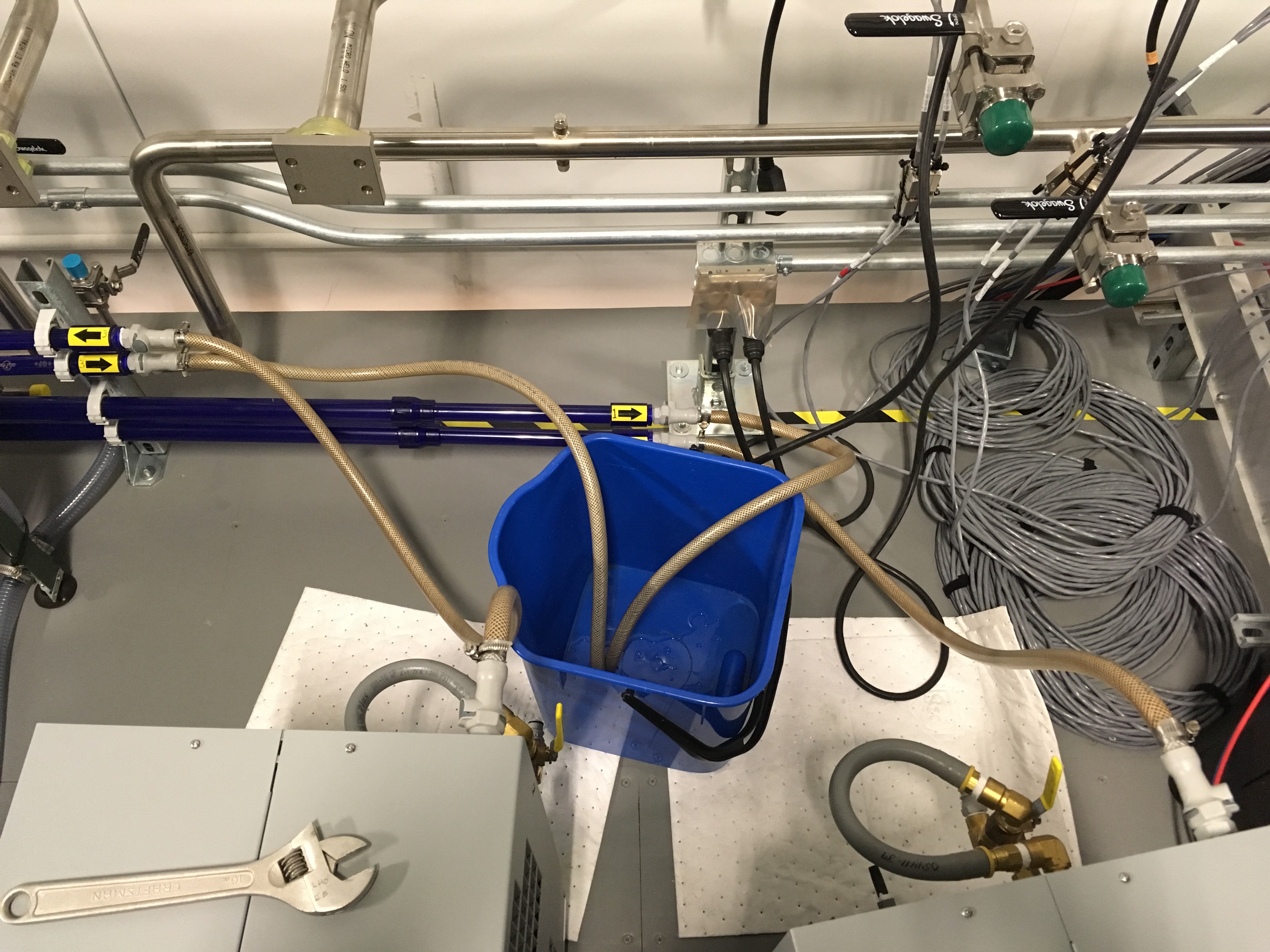
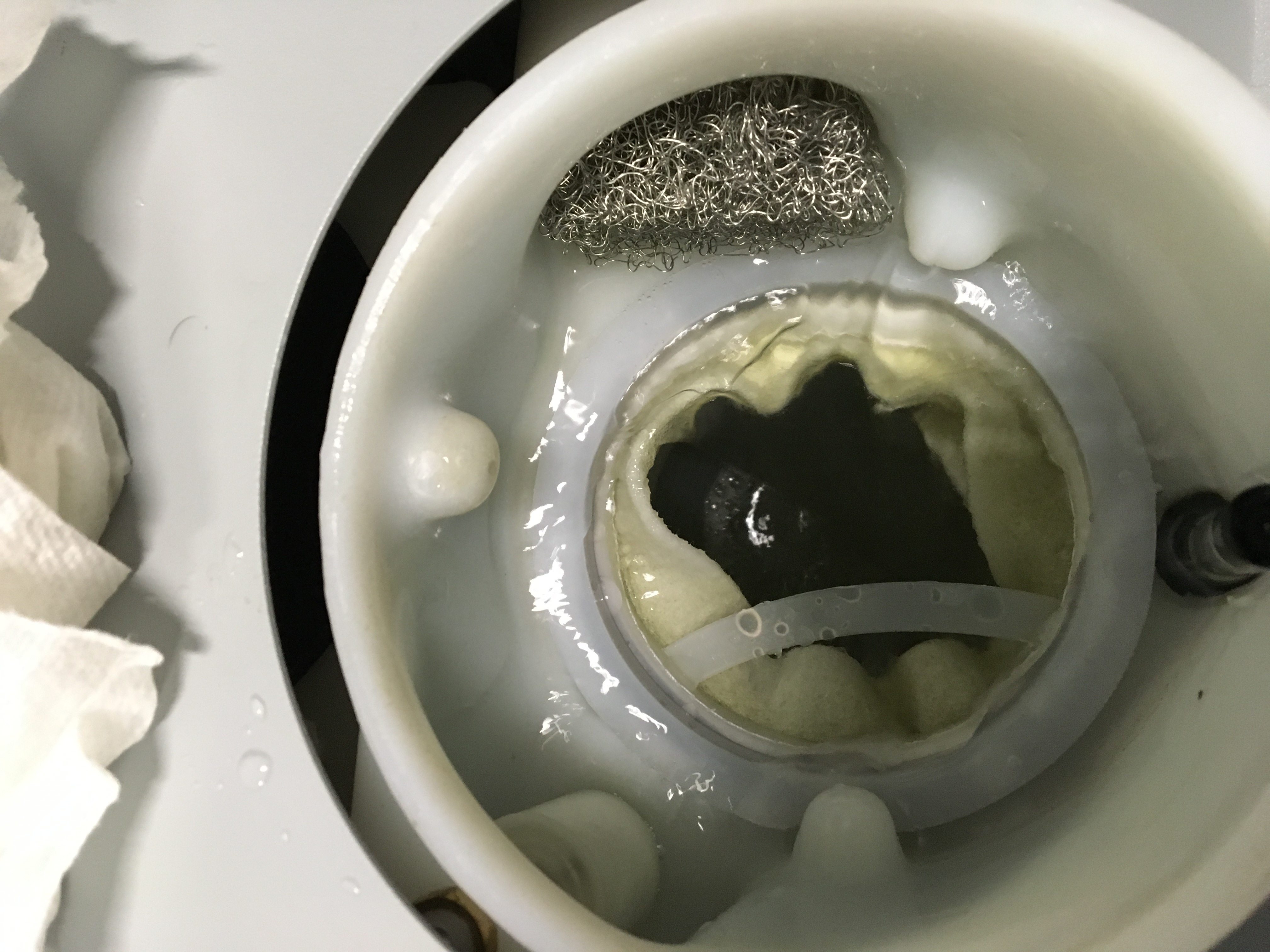
Each chiller was flushed with 10 gallons of water. The flushed water looked clean (no green tint, floating particulates). We put the quick connects back to the end of inlet hoses and reconnect them to the chillers. Once we put in new filters (which we rinsed with lab water), the filters started turning green right away. Once we made sure nothing leaked we recovered the TCS.
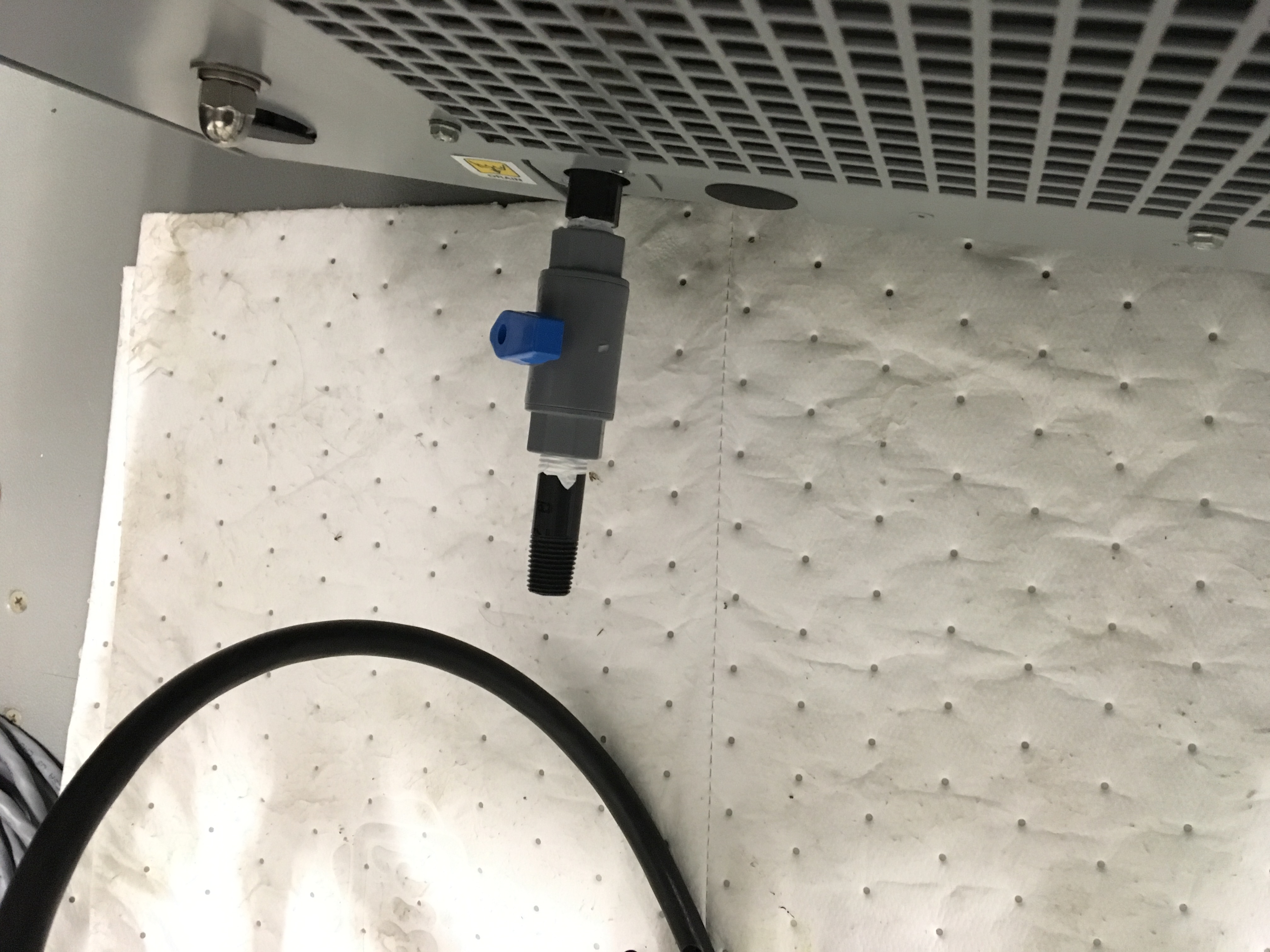
The drain pipe now has an extra fitting that allows a drain pipe to fit over for easy draining if we ever have to do this again.

Filed FRS #6330. I asked Fil to take a look at the AA and AI chassis associated with the DBB during the next maintenance window (10/4/2016). If those check out the problem is likely in the DBB control box that lives in the PSL rack in the LVEA.