gabriele.vajente@LIGO.ORG - posted 12:46, Thursday 13 August 2015 (20512)
SRC1 loop causing loss lock at ENGAGE_ASC
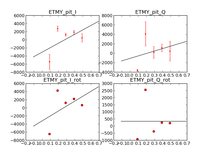
This morning the lock acquisition always failed at the ENGAGE_ASC step. We traced down the problem to the change in SRC1_Y input matrix: the error signal was changed from 2 * AS_B_RF36_I to -3*AS_A_RF36_I. We tried this transition manually with -20dB of loop gain, and altought the loop was moving the rror signal toward zero, the result was a misalignment of the IFO and unlock.
So for the moment being I com mented out this matrix change in the guardian. ENGAGE_ASC is now stable with this configuration.