TITLE: 03/21 Day Shift: 15:00-23:00 UTC (08:00-16:00 PST), all times posted in UTC
STATE of H1: Commissioning
OUTGOING OPERATOR: None
CURRENT ENVIRONMENT:
SEI_ENV state: CALM
Wind: 11mph Gusts, 8mph 5min avg
Primary useism: 0.02 μm/s
Secondary useism: 0.21 μm/s
QUICK SUMMARY:
We've been locked for 9.5 hours! More commissioning!
TITLE: 03/20 Eve Shift: 23:00-07:00 UTC (16:00-00:00 PST), all times posted in UTC
STATE of H1: Commissioning
INCOMING OPERATOR: None
SHIFT SUMMARY:
A return to Observing for H1 (first time since mid-Jan, and a return to Triple Coincidence with Virgo + both LIGO detectors for the first time since O3!)---this occured after about 90min of Commissioning work. It was a little bit of a rocky start with a wind storm with sustained winds in the 20mph range for almost half the shift (and gusts above 40mph). This made for several hours of down time (forgot to mark as "WIND" with OBSERVATORY MODE unfortunately). Eventually able to get back to Observing toward the end of the shift.
LOG:
After our windstorm, finally ready to get back to OBSERVING, but we had SDFs for PR3 (I could have sworn we had SDFs for PR3 at the beginning of the shift when we were racing to address the piles of SDF Diffs we had so we could get to Observing.). At any rate, the (3) channels are for Enabling the Input for (3) PR3 channels (see that attached photo of the SUSPR3 Diffs which were ACCEPTED).
Winds really picked up a bit shortly after we went to Observing. Have run an alignment, but the last 90mins have seen little action beyond DRMI....made it to OFFLOAD DRMI once. Will hold for an hour at LOCKING ARMS GREEN for an hour (and while I make lunch).
Let's assume the additional flat noise in the ~100 Hz region that might be limiting now (w.r.t. to O4a) is due to OMC length noise. Either the OMC lenght noise is larger than before, and coupling through the residual OMC length RMS noise, or the OMC lock has an offset.
Let's assume that the OMC was locked at the top of the resonance (no offset, to be confirmed with the new demodulation phase).
According to 76137, the two PZT responses are PZT1 = 11.3 nm/V, and PZT2 = 12.7 nm/V.
Following Sheila's note in 30510, the normalized OMC transmission (RIN) is given by [after correcting for a mistake in the coefficient multipling F]
RIN = 1 / (1 + (2 F (x0 + dx)/ lambda)^2 )
where F = 400 is the OMC finesse (76386), x0 is a static lock offset (or equivalent RMS fluctuation) and dx is OMC lenght noise (form example due to dither).
The amplitude of the dither line is 0.23 V peak, corresponding to a dither amplitude (peak) of A = 2.6e-9 m, using the PZT1 calibration above.
The locking error signal is obtained using a length modulation dx = A sin(wt) that gives a RIN = (2F/lambda)^2 A sin(wt) x0, where x0 is the offsetf from resonance of the OMC length. Once demodulated, this gives
OMC-LSC_I = (2F/lambda)^2 A/2 x0 = 7.3e8 error_signal_demodulated_RIN / m (note that 30510 seems to be wrong and missing some factors, thank you Elenna for checking)
This allows me to calibrate the OMC-LSC input signal. The RMS with the OMC locked is 4.7e-5 RIN, corresponding to 6.4e-14 m RMS of residual OMC fluctuation around the lock point.
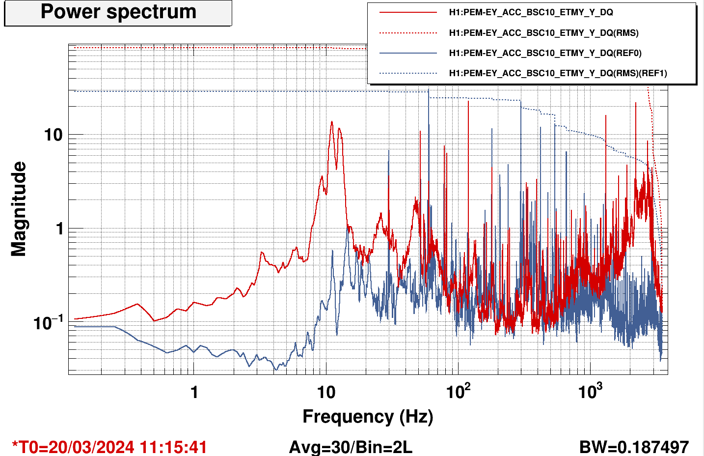
The flat noise in DARM is about 7e-21 m/rHz. Using the optical gain from the calibration measurement (3.4e6 LSC-DARM_IN cts/m) and the ratio LSC-DARM_IN / OMC_DCPD_NORM = 1.6e-5, I find an optical gain of 2.1e11 RIN/m for OMC-DCPD_NORM
Therefore the noise in DARM corresponds to a OMC-DCPD RIN of 1.5e-9 RIN/rHz
Noise coupling due to the residual OMC length RMS goes like (2F/lambda)^2 x_RMS dx_noise, where x_RMS is now the residual RMS motion computed above. Using this conversion, I found that the excess noise in DARM would correspond to a OMC length noise of 4e-14 m/rHz at 100 Hz. This still seems higher than the expected noise that should be in the 3e-16 m/rHz range (see for example section 8 of T1000276)
Tests to do:
In addition to the BSC10 accelerometer, the amount of floor motion also increases over the past 6 weeks, though not in a sudden fashion.
This does not correspond to the time of the most recent fan swap, judging by fan accelerometers.
New EX and EY Accelerometer Power Conditioners were installed 30 January 2024. This is roughly the same time as some of these jumps in the trend. The EY BSC 10 accelerometer cable had a questionable connector but still functioned so I believe we left it, it may need to be replaced.
https://alog.ligo-wa.caltech.edu/aLOG/index.php?callRep=75592
We replaced the loose connector but did not see any effect on the signal. While down there we looked at the output and found that channel 5 output was very noisy, and looking back at the notes in my prior ALOG, channel 5 = PEM EY BSC ACC X and back then it did not register as an accelerometer. I assume this accelerometer is not functional or the cabling is not correct. We plan to go back on Tuesday and track down the issue with this accelerometer and possibly repair the channel in the power conditioner chassis.
Other notes
The INPUT to CH3 on the power conditioner is "TBL-Y" accelerometer cable. When unplugged this affected "BSC-Y" signal plot.
The INPUT to CH4 on the power conditioner is "BSC-Z" accelerometer cable. When unplugged this affected "BSC-Z" signal plot. (this one was correct)
Looking back at my analysis of the drawings in the linked ALOG, the above note matches the drawings in the DCC D1300773. I propose we assume the cables are swapped incorrectly but labeled correctly, and we rearrange the cables to match the drawing.
Marc, Fil, Gerardo, Janos
Refer to LHO:76728.
Naoki, Daniel, Nutsinee
Today we increased RF6 from -22dBm to -13 dBm and 8 dBm. We saw excess noise at 8 dBm above 300Hz but no excess noise at -13dBm. REF 12 is the squeezing at -22dB before we started the test. Using the time from alog76553. REF9 and REF10 both show squeezing at -13dBm RF6 at different squeeze angle where one has a better sensitivity at low frequency bucket. REF13 shows squeezing at 8dBm RF6. The excess noise above 300Hz cannot be improved with squeeze angle. Investigation is required.
We turned off ADF sqz angle servo during the test. We readjusted the ADF squeeze angle demod phase and accepted the new value in the SDF.
We are parking RF6 at -12dBm. Since Daniel didn't like the unlucky number 13.
| Loop | Was (-22dBm RF6) | Now (-12 dBm RF6) |
| CLF gain | 10 | 0 |
| LO gain | -7 | -12 |
| FC LSC gain | -2.6 | -0.86 |
| FC ASC gain | 0.1 | 0.03 |
The -22dBm, -12dBm, 8dBm RF6 correspond to 9 uW, 28 uW, 420 uW CLF REFL power.
We rechecked the FDS -22dBm time as the time in the above plot wasn't sqz opitmized to the bucket. Can see in attached plot, CLF at -22dBm and -13dBm have the same SQZ in the bucket, as expected.
Looking back at the past data it seems we may not have adjusted the CLF ISS gain properly during the test causing our sqz level to be stuck at 3dB at kHz region. CLF_REFL_DC was oscillating when RF6 was at -13 dBm and at 8 dBm. This looks like an easy fix and we should try again at some point.
Daniel Nutsinee
Reducing the gain didn't seem to fix the oscillation. We cranked up the CLF power so the RF6 read 6dBm and went out to look at the signal on the scope. We saw 60kHz beat note on the OPO refl and a crooked 105kHz sinewave on the CLF refl. We don't know where the 60kHz beat on the OPO refl came from. We couldn't make any improvement by changing the CLF ISS gain.
After some investigation we realized the oscillation disappeared when we unplugged the RLF. The oscillation came back when the RLF was plugged back in. The oscillation associated with the RLF seemed obvious only when we operated at high power. Next time we try high CLF power again we should attenuate the RLF RF output to the AOM.
The funny thing was PMC refl saw this oscillation as well. We hope this was just an electronics cross talk.
For even higher CLF power with +6dBm at the RF6 demod, we set the CLF servo IN2 gain to-18dB (from 0dB), the CLF ISS gain to 0dB (from 17dB), and the ISS input set point to 2.037 (from 0.347).
SDFs from green initial alignment setpoints
Jenne was pecking away at SDFs (separate alogs), Jennie/Evan did OMC (I took screenshot below), Louis helped with PCal.....Squeezer work is currently active, so will wait for that team to ACCEPT Squeezer!
Pecking away at some SDFs in preparation for OBSERVING tonight:
Easy Ones To ACCEPT:
More Involved to ACCEPT:
These changes were accpted, but need to be set again after aligning the FC IR transmission.
Noaki added a gain increase to the CAM1 PIT loop for faster convergence. It should be in the guardian, so I've accepted it in SDF.
DHARD yaw new FM8, alog 76314.
Accepting AS_A offset engagement in Observe.snap. Values from alog 76500
I've accepted dark offsets for the LSC and ASC PDs in SDF for the Observe.snap files.
Naoki, Nutsinee, Camilla
We turned the SQZ_ANG_ADJUST servo back to it's O3a nominal ADJUST_SQZ_ANG_ADF. Changed sqzparams.use_sqz_angle_adjust to True and reloaded SQZ_MANAGER and SQZ_ANG_ADJUST.
Set H1:SQZ-ADF_OMC_TRANS_PHASE as 133deg, new scan (as in 76434) running now to check what angle is best for total squeezing.
Accepted at H1:SQZ-ADF_OMC_TRANS_PHASE = 120. This seems to give us the best range but not high frequency SQZ. Plot attached.
We optimized the sqz angle after high CLF test and readjusted the AADF demod phase.
We should check the ADF offset with a more themalized IFO as the SQZ angle servo seems to have pulled even the yellow BLRM to a worse location, see attached.