Displaying reports 42981-43000 of 88648.Go to page Start 2146 2147 2148 2149 2150 2151 2152 2153 2154 End
Reports until 08:20, Friday 22 February 2019
LHO General
corey.gray@LIGO.ORG - posted 08:20, Friday 22 February 2019 (47071)
Morning Status

TITLE: 02/22 Day Shift: 16:00-00:00 UTC (08:00-16:00 PST), all times posted in UTC
STATE of H1: Commissioning
OUTGOING OPERATOR: None
CURRENT ENVIRONMENT:
    Wind: 5mph Gusts, 2mph 5min avg
    Primary useism: 0.05 μm/s
    Secondary useism: 0.29 μm/s
QUICK SUMMARY:

Foggy drive in before 8am.
EQ recovery was not that bad according to Jenne (no SUS tripped and SEI were in an EQ state).  FSS work by Peter started at 13:10utc, and during this Jenne performed some dark measurements.  Oh, and this H1 downtime allowed Bubba to clear EY to allow first access to EY since snowmageddon.  Jenne ran an initial alignment.  Locking H1 now.

LHO General
corey.gray@LIGO.ORG - posted 08:16, Friday 22 February 2019 (47069)
Morning Status

TITLE: 02/22 Day Shift: 16:00-00:00 UTC (08:00-16:00 PST), all times posted in UTC
STATE of H1: Commissioning
OUTGOING OPERATOR: None
CURRENT ENVIRONMENT:
    Wind: 5mph Gusts, 2mph 5min avg
    Primary useism: 0.05 μm/s
    Secondary useism: 0.29 μm/s
QUICK SUMMARY:

Jenne reported some recovery from the big EQ, but said it was not bad (no SUS tripped and SEI systems in the EQ state).  Jenne just finished an Initial Alignment.  OH, and earlier this morning since we had the PSL down, let Bubba clear the snow drifts down to EY & the EY chiller yard (so now we can finally get to EY post-snowmageddon.

Locking H1 now.

H1 ISC
jenne.driggers@LIGO.ORG - posted 07:55, Friday 22 February 2019 - last comment - 19:55, Friday 22 February 2019(47067)
OMC DCPDs to Low Z

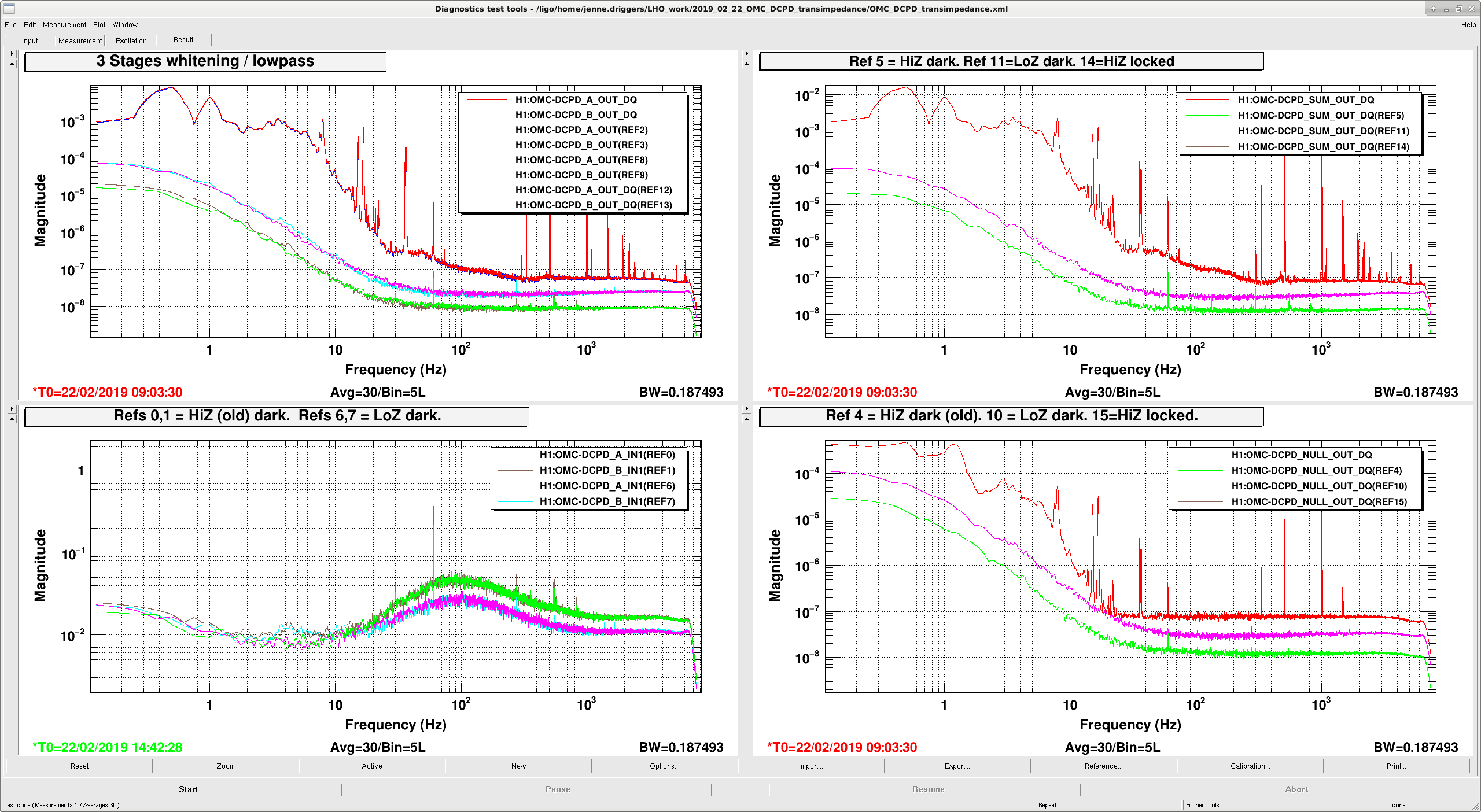
As a step toward trying larger DARM offsets, I have flipped the rocker switch on the OMC DCPD whitening chassis to its LowZ state.  To match this, I have turned off the HiZ filter in the H1:OMC-DCPD_A and H1:OMC-DCPD_B filter banks.

Attached are some spectra showing the dark noise measured this morning in both the old HiZ and new LowZ states, as compared to last night's 30W lock at NomLowNoise.  All of these spectra are taken with both stages of whitening on, as well as the lowpass.  Green and brown are with the old HiZ settings, pink and cyan are with the current LowZ settings, and the red and dark blue (also refs 12-15 underneath the red and blue) are from last night's lock with the usual 20mA of light.

Images attached to this report
Comments related to this report
jenne.driggers@LIGO.ORG - 08:42, Friday 22 February 2019 (47073)

In prep_dc_readout, with OMC locked, I changed the height of the dither line from 750 counts to 630 counts, to match the OMC length UGF of 6 Hz measured 2 days ago.

sheila.dwyer@LIGO.ORG - 19:55, Friday 22 February 2019 (47093)

We reverted these changes (dither amplitude, HiZ switch and compensation for HiZ) so that people can get to low noise tonight without redoing the feedforward.  

H1 SUS
jenne.driggers@LIGO.ORG - posted 07:45, Friday 22 February 2019 - last comment - 16:17, Tuesday 26 February 2019(47066)
SR3 oplev dead?

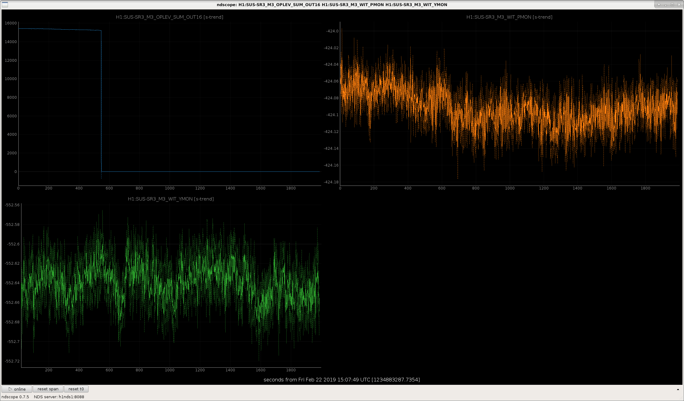
Just noticed a warning on DIAG_MAIN that SR3 oplev was low.  SR3 is aligned, and I restored all SEI to their nominal status (clicked "recover EQ", and requested sensor correction to be WINDY), so there should be no reason for SR3's oplev to be low.

Attached is a plot of the Oplev sum, as well as the lowest stage OSEMs, showing that the optic didn't move, but the sum disappeared.

Recall that we do not use the SR3 oplev for any damping, so while we should fix this soon, we shouldn't break lock to do so.

Images attached to this report
Comments related to this report
jeffrey.kissel@LIGO.ORG - 08:14, Friday 22 February 2019 (47070)AOS
Now associated with FRS Ticket 12394.
jason.oberling@LIGO.ORG - 10:22, Friday 22 February 2019 (47077)AOS

Will investigate at the next available opportunity, likely during the next maintenance window (2-26-19), unless this gets deemed a higher priority.  Tagging this as AOS in addition to SUS (OpLev is technically an AOS system).

jason.oberling@LIGO.ORG - 16:17, Tuesday 26 February 2019 (47138)SUS

The laser is definitely dead.  Unfortunately, due to a series of consecutive failures in the lab while tweaking our spare stock for glitch-free operation, we currently have no spare lasers; all of our spares (our 3 designated spares and 2 others) are currently getting refurbished.  I have pinged the manufacturer for an update, will request a loan from 3IFO to use in the interim.

H1 AOS
craig.cahillane@LIGO.ORG - posted 02:35, Friday 22 February 2019 - last comment - 08:59, Friday 22 February 2019(47065)
NLN achieved
Georgia, Craig

Tonight we locked on ETMX by increasing the L2 LOCK drive to 30 from 15 again.  Sheila, Keita and Jenne have all been thinking about the DARM actuator stability, we decided to not duplicate their effort and try what worked last night.  We were able to reach NLN with the attached settings (attachment 1).

We retuned the MICH feedforward for our new actuator change.  The guardian now turns on MICHFF FM5 "Feb 21", the filter in attachment two.  If we return to a low PUM gain of 15, we will have to engage FM4 "Feb16b" instead.

Georgia measured the 9 MHz RIN coupling to DARM, and found it to be high again (like the green in attachment one of alog 47008).  This is after the original OMC PZT driver was reinstalled yesterday.

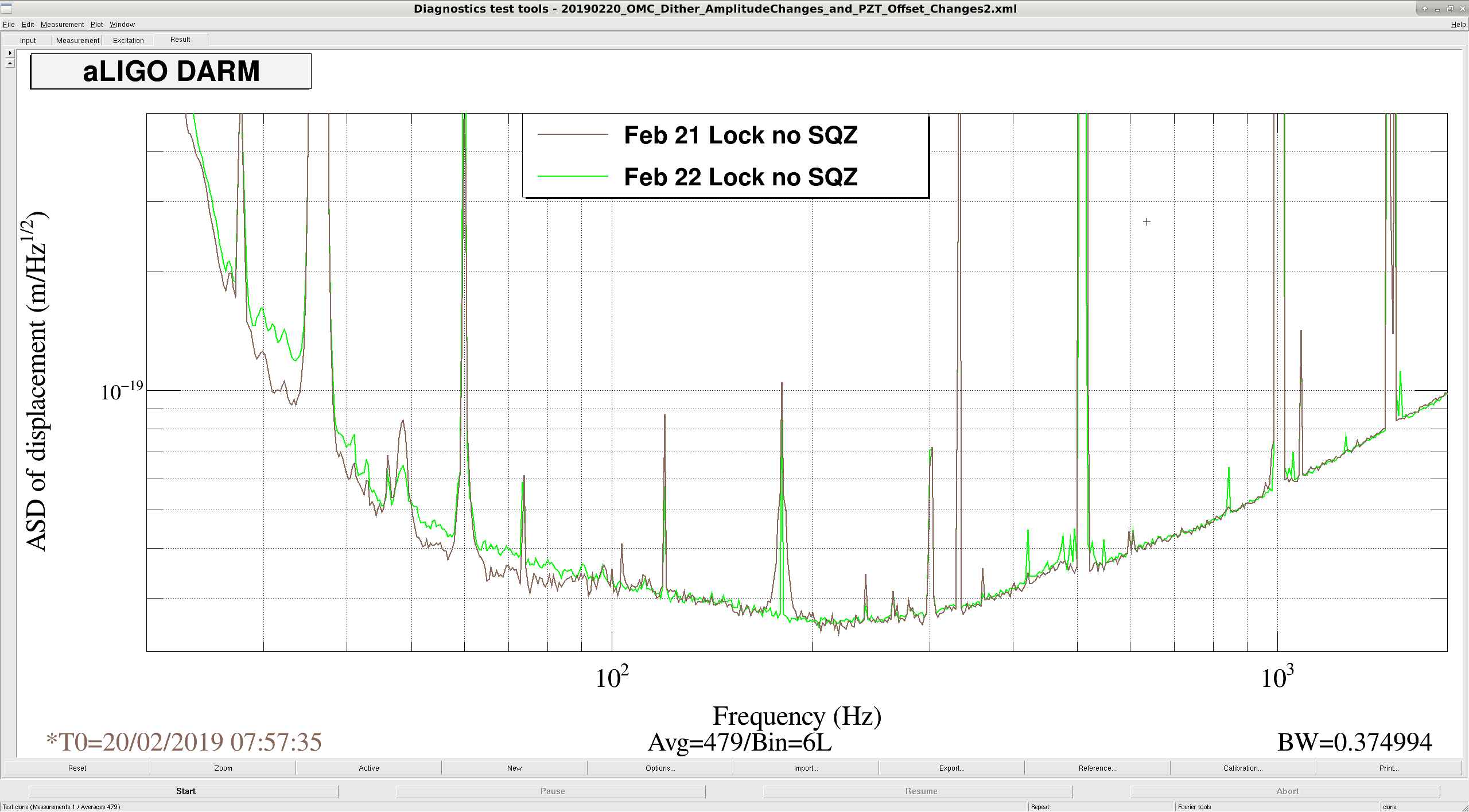
I tuned the front-end calibration for higher PUM gain and adjusted the DARM ERR gain from 1.2 to 1.177 to get correct shot noise.  Georgia shut the SQZ beam diverter to avoid the anti-squeezing we were injecting.  This got us back to low noise with no squeezing, with 83 Mpc range reported (which is actually around 90 Mpc with proper calibration).  The low frequency noise seems to be worse, this could be a result of the DARM actuator change not being properly calibrated, or real because of increased 9 MHz coupling.

A 7.7 magnitude earthquake hit.  We pressed the Really Big Earthquake button.

Images attached to this report
Comments related to this report
corey.gray@LIGO.ORG - 08:59, Friday 22 February 2019 (47075)OpsInfo, SEI

Tagging this with SEI & OpsInfo for JIm.

LHO General
corey.gray@LIGO.ORG - posted 21:07, Thursday 21 February 2019 (47046)
DAY Operator Summary

[Whoops, noticed I hadn't posted this, so here it is.]

TITLE: 02/21 Day Shift: 16:00-00:00 UTC (08:00-16:00 PST), all times posted in UTC
STATE of H1: Commissioning
INCOMING OPERATOR: None
SHIFT SUMMARY:

H1 locked at 30W since 16:50UTC (9:50am), where we held it for most of the shift.  First few hours Rahul and I worked on damping violin modes (I didn't have much luck, but Rahul knocked down a couple).  Commissioners have had H1 in this lock for their work.  H1 did drop toward the end of the shift...so far have not tried an Initial Alignment...

Other Notes:

LOG:

H1 ISC
jenne.driggers@LIGO.ORG - posted 17:50, Thursday 21 February 2019 - last comment - 08:48, Friday 22 February 2019(47063)
EZCA connection errors in just the wrong place causing locklosses today

[Jenne, Georgia, Sheila, Craig, Dan, Danny]

We've lost lock a few times today while trying to increase the power, so that we can try the new DARM loop scheme (crossover shaping) that Sheila has cooked up.  It turns out that the problem was an ezca connection error in the main part of the INCREASE_POWER guardian state, causing the ISC_LOCK guardian to freeze while trying to reconnect.  However, before the error, ISC_LOCK guardian has already requested the laser power guardian to increase the laser power, which it starts to do.  But then, since ISC_LOCK guardian is frozen, the DARM fringe offset is not being adjusted to match, and we lose lock.

Happily, the ezca commands that were causing trouble were setting the RPC filter states, but they don't actually need to be in the guardian at all, since we don't ever change them.  So, they are now removed from that state, and we're almost ready to try increasing the power again.

Comments related to this report
jeffrey.kissel@LIGO.ORG - 08:48, Friday 22 February 2019 (47074)CDS, GRD
This is another instance of the bug reported in FRS Ticket 12067. Not sure what other documentation exists on this (I feel like much more progress has been made, but not reported in *that* ticket).
H1 SUS
rahul.kumar@LIGO.ORG - posted 16:39, Thursday 21 February 2019 (47062)
Violin mode damping
Correy and Rahul

This morning we spent a fair bit of time damping the fundamental violin modes of the test mass - ITMY, ITMX and ETMY. Given below are the frequencies we tackled. 

1. ITMY mode 8, freq: 501.755 Hz applied gain 5 - reduction by 1 order of magnitude (amplitude)
2. ITMX, mode 2, freq: 504.891 Hz, applied gain 34
3. ETMY, mode 1, freq 510.75, applied gain 0.2

To identify the modes (between 500Hz - 520 Hz) we looked at the DTT (dignostic test tools) to obtain the real time power spectrum and a reference spectrum (from Nov 10, 2018). Next we tried looking at the SUS_CUST_VIOLIN_OVERVIEW.adl window, but we did not trust the frequencies listed over there. Hence we opened the damping filters of the test mass and looked for the closest matching frequencies. If there are two peaks very close by then we went by trial and error (apply some damping and if the amplitude decreases then we are pushing the right fibre, else set the gain back to the default value). I think with more experience we should be able to properly identify all the modes and hence update the numbers on the overview.adl window for quicker response.  

Jenne taught us a shortcut for looking at violin mode scope for a single mode, given below is the path
Locking.adl - violins scopes (pink box) -  generate single mode - feed in the test mass name and mode number to obtain the real time plot.
H1 TCS (TCS)
aidan.brooks@LIGO.ORG - posted 14:03, Thursday 21 February 2019 (47060)
Summary of TCS settings for 30W lock

At Gabriele's request, I've summarized the TCS settings for 30W operation.

During Full IFO

ITMX:


ITMY:

H1 CAL (CAL, ISC, SUS)
evan.goetz@LIGO.ORG - posted 13:12, Thursday 21 February 2019 (47059)
DARM loop critique for model 19 Feb 2019 using pyDARM
Code to create DARM loop critique plots has now been integrated into the pyDARM infrastructure. An IFO and run agnostic script was written as is stored here:
$CALSVN/trunk/Common/pyDARM/darm_loop_critique.py

You point it at a run, IFO, model file, function name inside the model file (typically "modelPars"), and provide an output file name (e.g., "critique") and you will end up with a series of individual plots plus a concatenated file under the output file name provided. Ex:
$ python3 darm_loop_critique.py --run=O3 --IFO=H1 --DARMmodelfile=modelparams_H1_20190219 --modelFunction=modelPars --outputfile=critique

Attached is the concatenated figures for the model file modelparams_H1_20190219:
1) Open loop gain
2) Open loop gain zoom around unity gain frequency
3) Closed loop gain
4) DARM digital filtering
5) Optical plant response
6) Output filter bank to test mass displacement
7) SUS digital filters for each stage L1, L2, and L3 (DARM CTRL to output filter bank)
8) Actuator authority for each stage L1, L2, L3, and the total (LOCK IN to displacement)
9) Zoom at actuator authority cross-over for each stage L1, L2, L3, and the total (LOCK IN to displacement)
10) Zoom at actuator authority high frequency--above the DARM UGF--for each stage L1, L2, L3, and the total (LOCK IN to displacement)
11) DARM loop control (DARM IN to displacement)

Figure files are stored in $CALSVN/trunk/Runs/O3/H1/Results/Critique/
Non-image files attached to this report
H1 SQZ (SQZ)
nutsinee.kijbunchoo@LIGO.ORG - posted 10:16, Thursday 21 February 2019 (47054)
Added SQZ automation to IFO_LOCK guardian

Jenne, Nutsinee

IFO_LOCK guardian now manages SQZ_LOCK_L1 which is a manager to all other squeezer guardians. It will take SQZ system (except for TTFSS and SHG) to DOWN and close the pump flipper to preserve the fiber. In 'LOWNOISE_LENGTH_CONTROL' IFO_LOCK guardian will take squeezer to a ready state and wait there until 'INJECT_SQUEEZING'. At this state the guardian will determine if squeezer is good to go. If True, it will open the beam diverter and lock the LO loop. If False, it will give user a message and move on without trying anything (for now, until we really really need squeezer to be on all the time).

H1 PSL (PSL)
peter.king@LIGO.ORG - posted 08:31, Thursday 21 February 2019 - last comment - 11:38, Thursday 21 February 2019(47049)
More FSS measurements
Following on from yesterday's measurements.

    I checked the alignment on the RF photodiode (31 mV locked, 135-140 mV unlocked).  Took a transfer
function measurement before and after adjusting the alignment (C28F15.tif, C28F15.txt for data).  No
appreciable difference (32 mV locked, ~146 mV unlocked) in the transfer function.

    For reference I took the same measurement with the common gain slider at 20 dB and the fast gain
slider at 9 dB, ie its old settings (see C20F9.tif, C20F9.txt for data) and sure enough the UGF dropped.

    The mixer monitor (TP3) was plotted with the FSS locked and unlocked but with light incident on the
RF photodiode (ULOCKED.tif, ULOCKED.txt for data).
Images attached to this report
Non-image files attached to this report
Comments related to this report
peter.king@LIGO.ORG - 09:28, Thursday 21 February 2019 (47053)
Check the power (light) on the photodiode at the next opportunity.
daniel.sigg@LIGO.ORG - 11:38, Thursday 21 February 2019 (47057)

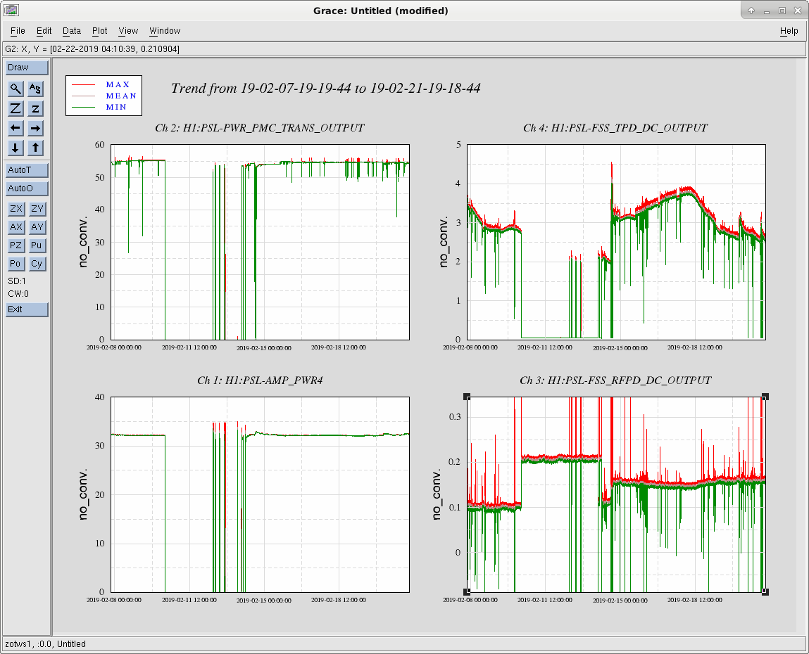
The FSS RFPD DC readback is probably broken. The filter module implements a gain of -0.05, this isn't the conversion factor from counts to volts; it should be 3.05E-4 (as can be seen in FSS TPD DC). Furthermore, when the PSL was off, the readback value was 0.2; this only corresponds to -4 counts. When locked, the readback hovers around 0.15, i.e., -3 counts.

Images attached to this comment
H1 DetChar
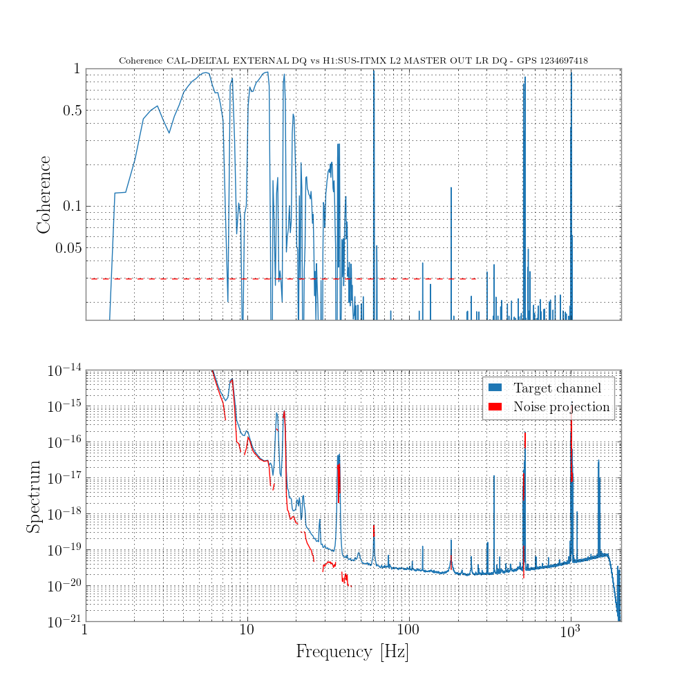
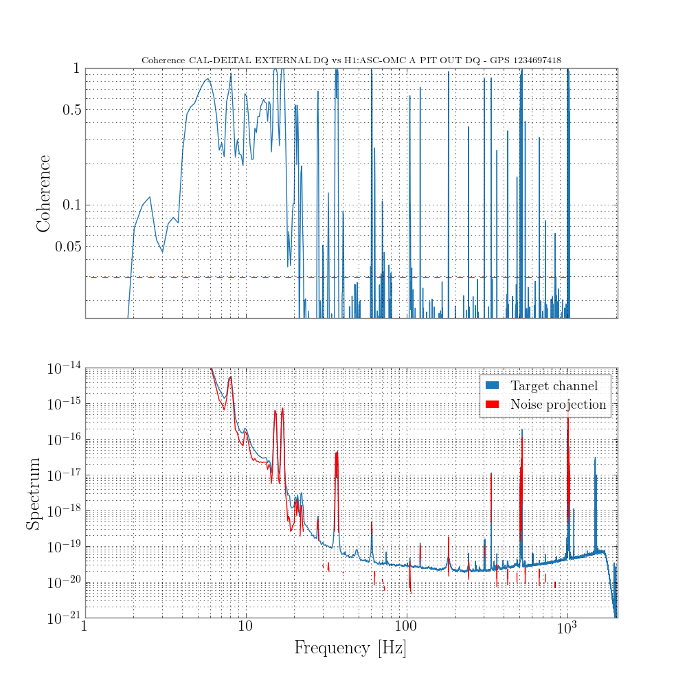
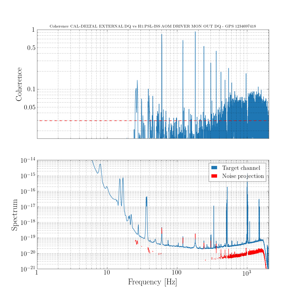
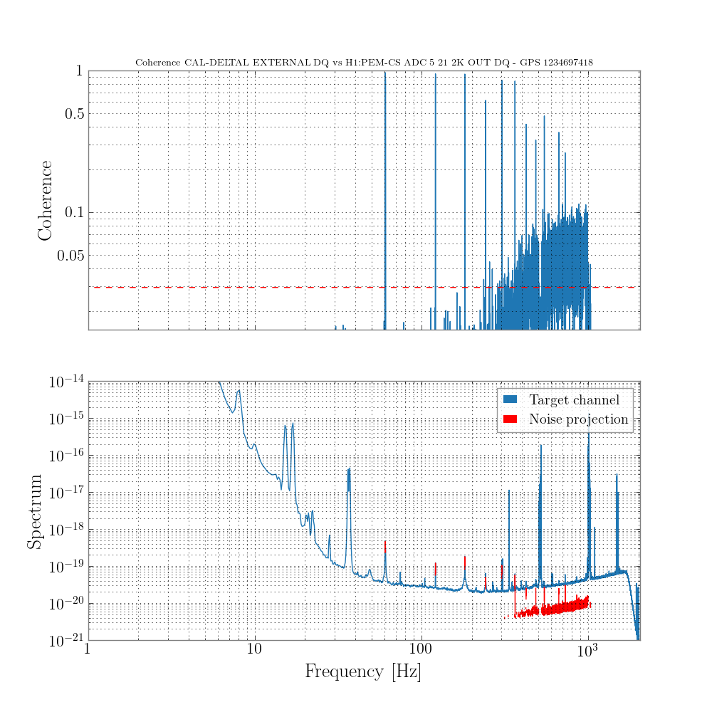
gabriele.vajente@LIGO.ORG - posted 20:10, Wednesday 20 February 2019 - last comment - 20:54, Thursday 21 February 2019(47033)
BruCo scan for

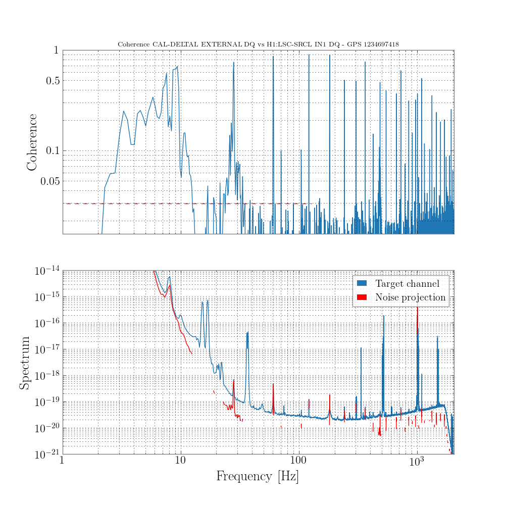
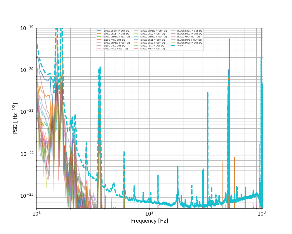
A BruCo scan for the "improved spectrum" mentioned in 47011 is available at the link below:

https://ldas-jobs.ligo.caltech.edu/~gabriele.vajente/bruco_lho_1234697418b/

I didn't use exactly the same time as in the posted spectrum, but instead used a quiet period with good range.

Some highlights:

Images attached to this report
Comments related to this report
gabriele.vajente@LIGO.ORG - 15:42, Wednesday 20 February 2019 (47036)

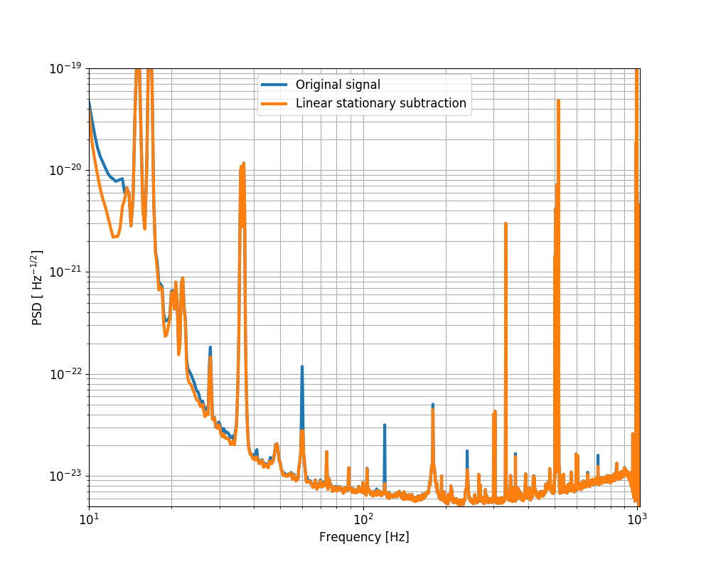
The effect of a linear noise subtraction of ASC and LSC control signals is shown below. This subtraction uses the parametric technique described in T1800552.

Images attached to this comment
gabriele.vajente@LIGO.ORG - 20:54, Thursday 21 February 2019 (47064)

The coherence with ASC-OMC_RIN_OUT_DQ and similar signals is due to the fact that at low frequency the DARM noise is large enough to dominate over those signal sensing noise. This has been confirmed by taking the transfer function ASc-OMC_RIN / DARM_IN1 during a DARM injection and using it to project ASC-OMC_RIN_OUT_DQ into DARM. 

H1 AOS
gabriele.vajente@LIGO.ORG - posted 09:45, Wednesday 20 February 2019 - last comment - 14:19, Friday 22 February 2019(47027)
Update on Power in high order modes due to point absorber ITM lens

This is an update on my previous entry 46952

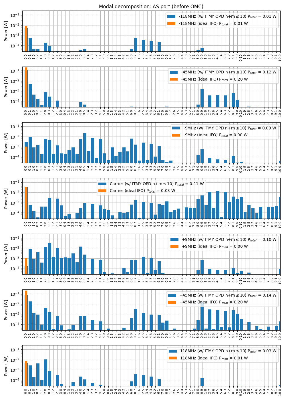
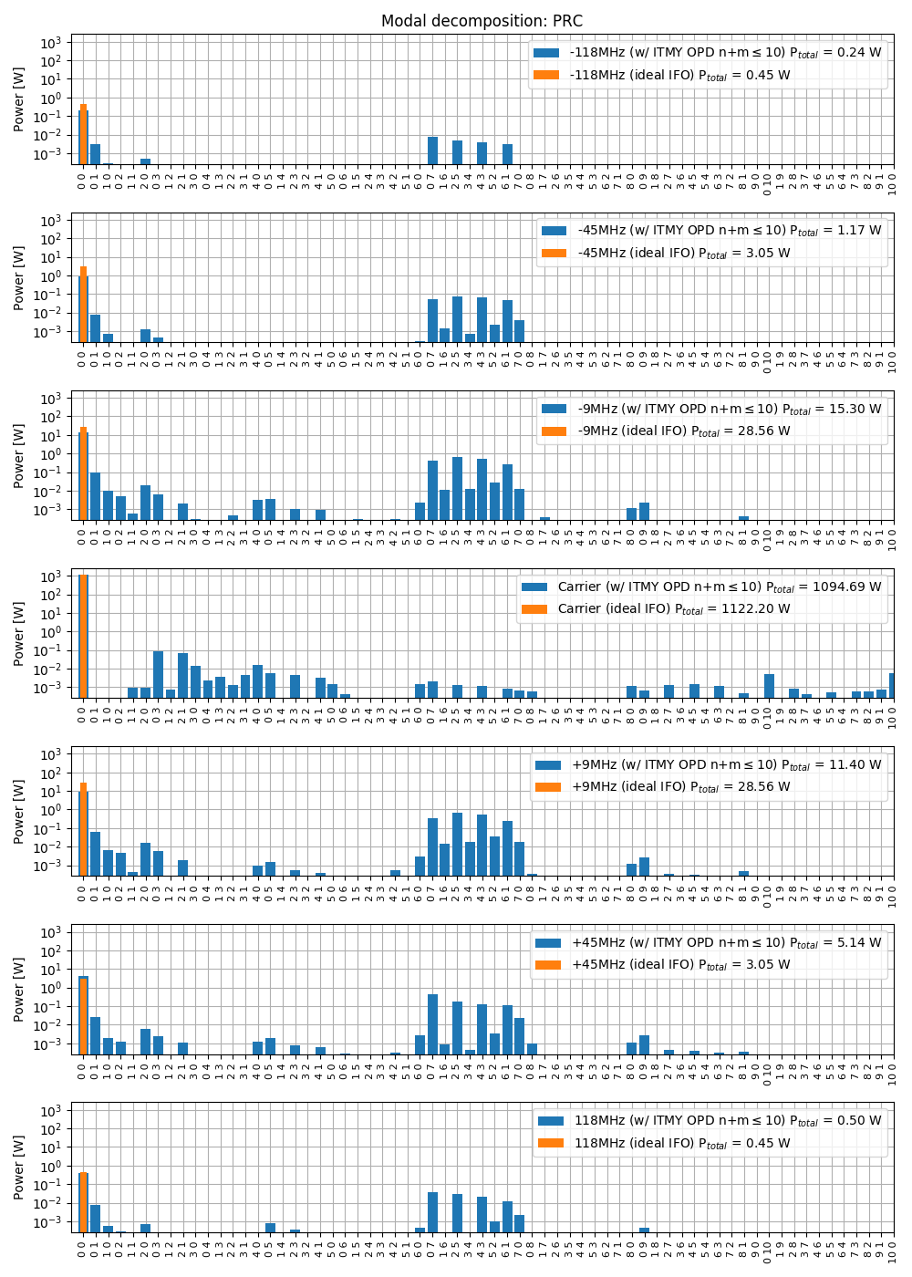
Field content

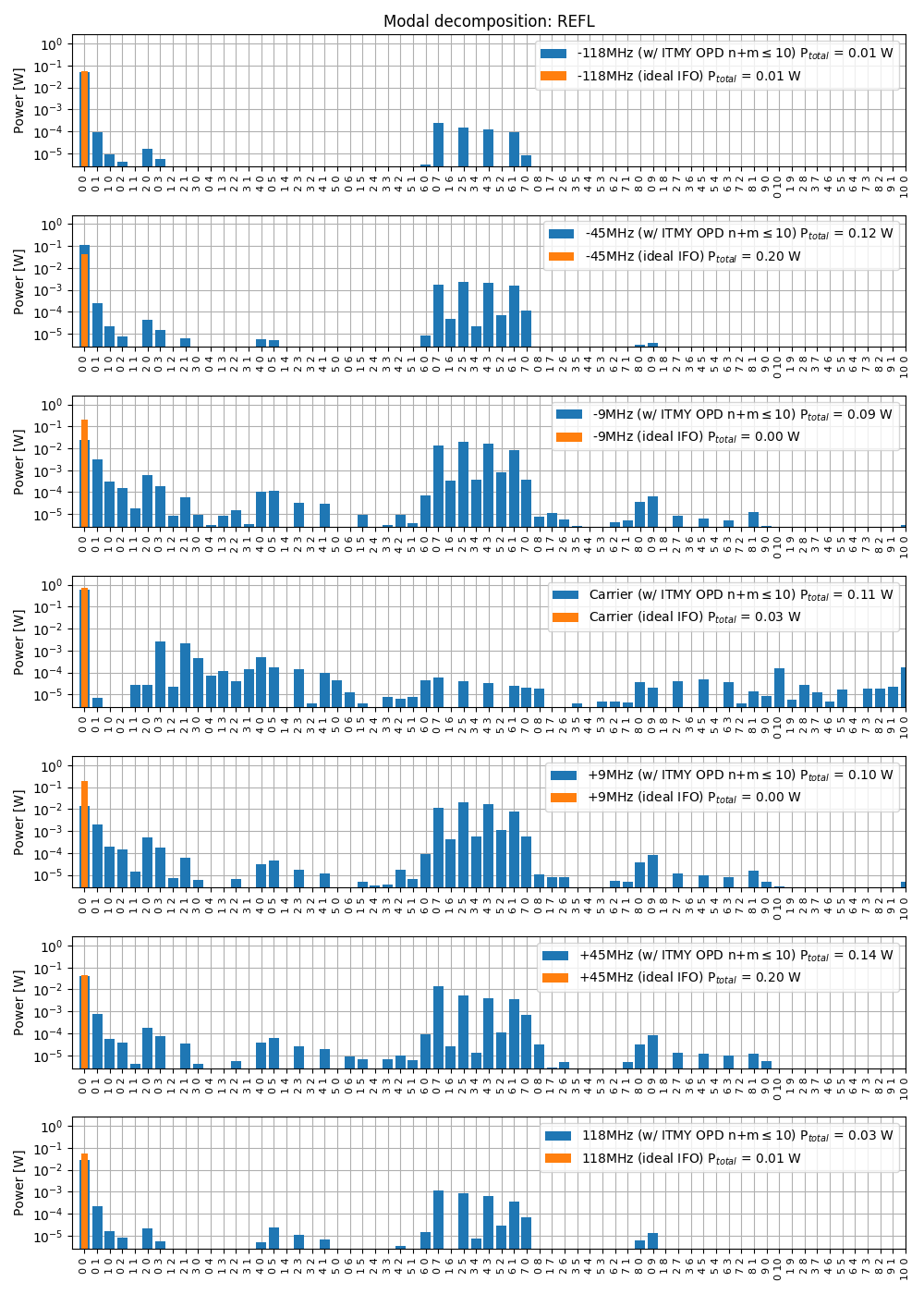
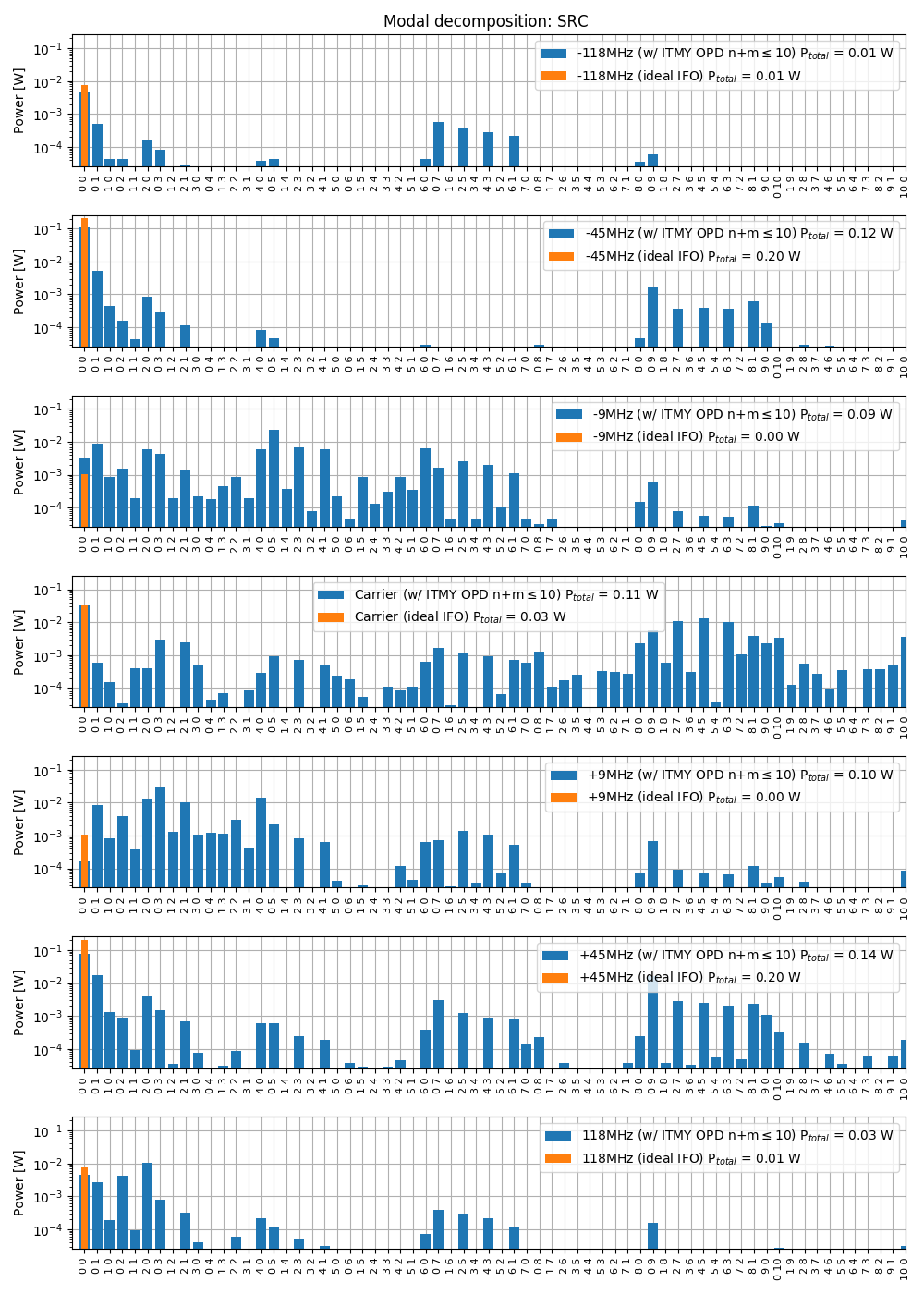
Using the optical path distortion measured by the HWS (provided by Aidan, see also 46127 and 46888) I simulated the mode content at various ports in a dual recycled Fabry-Perot Michelson interferometer. The simulation is done with MIST, using Hermite Gauss modes up to order 10, and locking the interferometer using simulated error signals. In the original entry 46952, the path distortion was about half of what we expect at 26 W (because the wavefront map provide by Aidan corresponds to a power step of about 15 W). So in the results considered here I multiplied the map by two.

Only the optical path distortion in the ITM is included, there is no deformation of the HR surface.

Each of the attached plots show the distribution of power into each modes, assuming 26 W of input power, 60ppm or round trip losses per arm. The orange traces are there for comparison, to show that in a ideal IFO, all power is in the fundamental TEM00 mode.

Interestingly, the point absorber seems to create some 9MHz sideband power in modes of order 9 at the AS port, which we believe are the culprit for the high RF9 modulation noise coupling.

RIN coupling

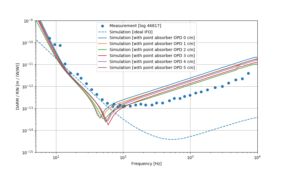
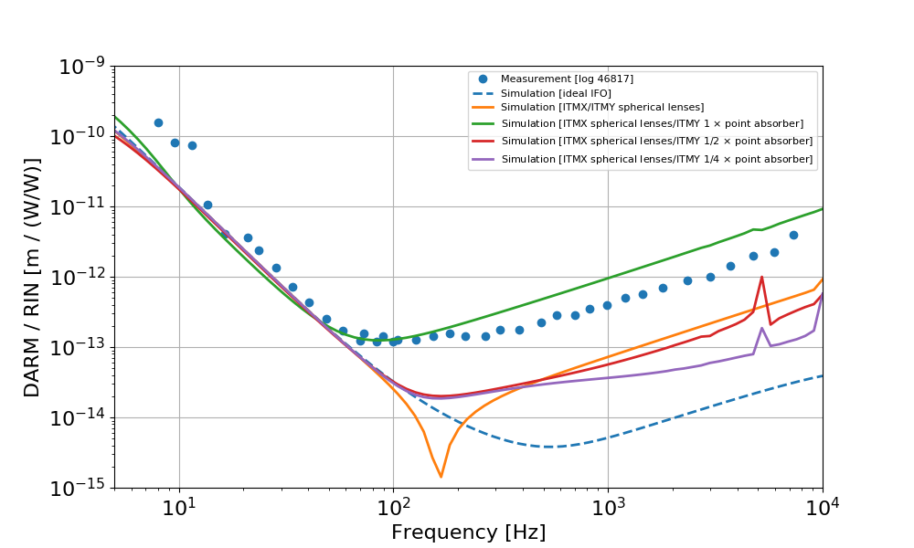
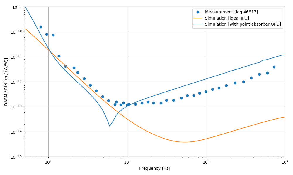
Using the same simulation described above, I could compute the coupling of input RIN to DARM. The result is shown below, compared with Craig's measurement from 46817. The distortion produced by the point absorber seems to explain qualitatively (even though not quantitatively) the increased coupling at high frequency. The magnitude of the coupling is larger in simulation, but roughly ok. The coupling scales with the amplitude of the optical path distortion, and it's likely to change if the point absorber is moved by a cm or two, probably within the uncertainty of the beam center position in the HWS map.
 

Sidebands RIN 

According to the simulation, there is about 1 mW of 9MHz sidebands power in the modes of order 9. Assuming that all of this mode is transmitted through the OMC, we can compute the DARM noise corresponding to sideband RIN:

DARM = SB_RIN * SB_POWER / (OMC_DC / DARM) 

From 46985 I estimate a DARM noise at a level of DARM ~= 5e-20 m/rHz at 100 Hz. From the simulation I have OMC_DC / DARM ~= 1.2e10 W/m, from which 

SB_RIN ~= 4e-7 /rHz

is the level of 9 MHz sidebands RIN that would explain the DARM noise, assuming it's all due to RF9 TEM9 mode leakage.

Images attached to this report
Comments related to this report
gabriele.vajente@LIGO.ORG - 09:21, Thursday 21 February 2019 (47052)

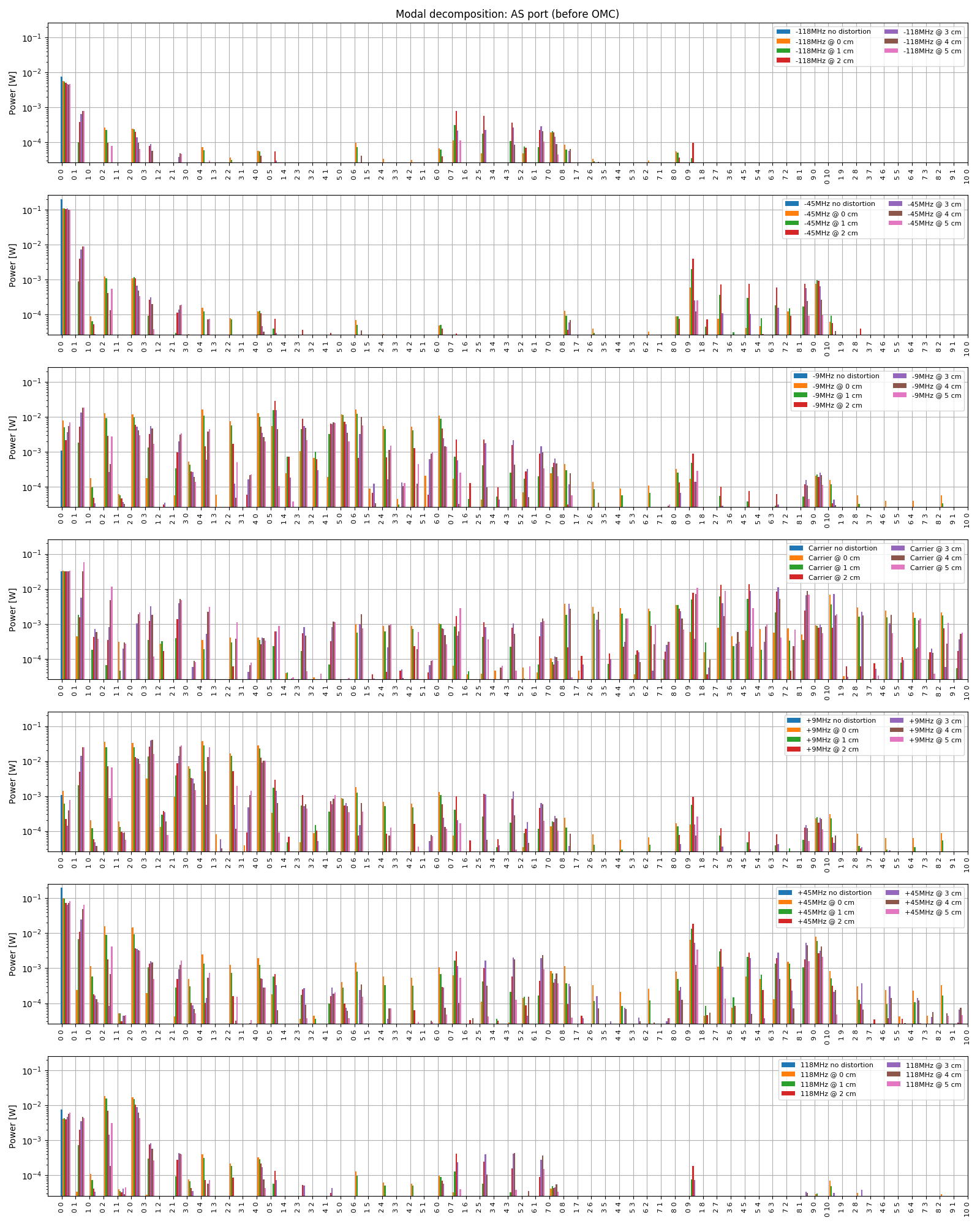
The position of the point absorber has, as expected, an effect on the simulation results. Here I started by centering the peak of the optical path distortion (OPD) at the center of the beam, and then move it to the side by steps os 1 cm, up to 5 cm from the center. I maintained the same peak amplitude of the OPD, so the shift does not take into account the change in the power that is actually absorbed. This simulation is just to get a feeling of how much the results change because of the uncertainty of the beam center position w.r.t. to the HWS frame.

The first plot shows that the coupling of RIN to DARM changes a bit, but not much, with the absorber position.

The second plot shows the mode content at the AS portfor the different positions. I realize this is a busy plot and hard to get much information out of it. I'll try to find a better representation soon.

CAVEAT: in all the simulations reported so far, I have included only the point absorber map on the ITMY substrate. To have a more realistic simulation, I should include the intrinsic and thermal lenses in both ITMs, as well as the effect of Ring Heaters and CO2 laser. Working on it.

Images attached to this comment
gabriele.vajente@LIGO.ORG - 14:19, Friday 22 February 2019 (47085)

Updates

  1. included thermal, static, CO2 and RH lenses as described by Aidan in 47060 
  2. when using the ITMY map with the correct amplitude, the simulation was not able to properly lock using the error signals. It turns out that the SRCL lock is fragile, and the zero is not quite right.
  3. I repeated the simulation by locking all d.o.f.s except SRCL. The DARM transfer function looks reasonable. But the RIN coupling depends a lot on the locking point. This is not new, we already know from old simulations that the MICH operating point can change the coupling of intensity noise at high frequency (see LLO 14091)
  4. with the "improved" locking, the simulation gets quite close to the measured RIN coupling

In the figure below, the coupling from RIN to DARM is shown for three configurations

  1. ideal IFO, all perfectly matched, no lenses, no mismatch
  2. spherical lenses: both ITMX and ITMY substrates contain a spherical lens with focal given by Aidan's numbers (ITMY self heating is modeled with an uniform absorption of 0.36 ppm)
  3. sperical lens in ITMX, measured point absorber map in ITMY (full amplitude of the optical path distortion, 1/2 of the amplitude and 1/4 of the amplitude for reference)


Images attached to this comment
H1 TCS (TCS)
aidan.brooks@LIGO.ORG - posted 16:00, Sunday 17 February 2019 - last comment - 14:07, Thursday 21 February 2019(46976)
Commissioning guide for the custom H1ITMY CO2 mask: Step 1

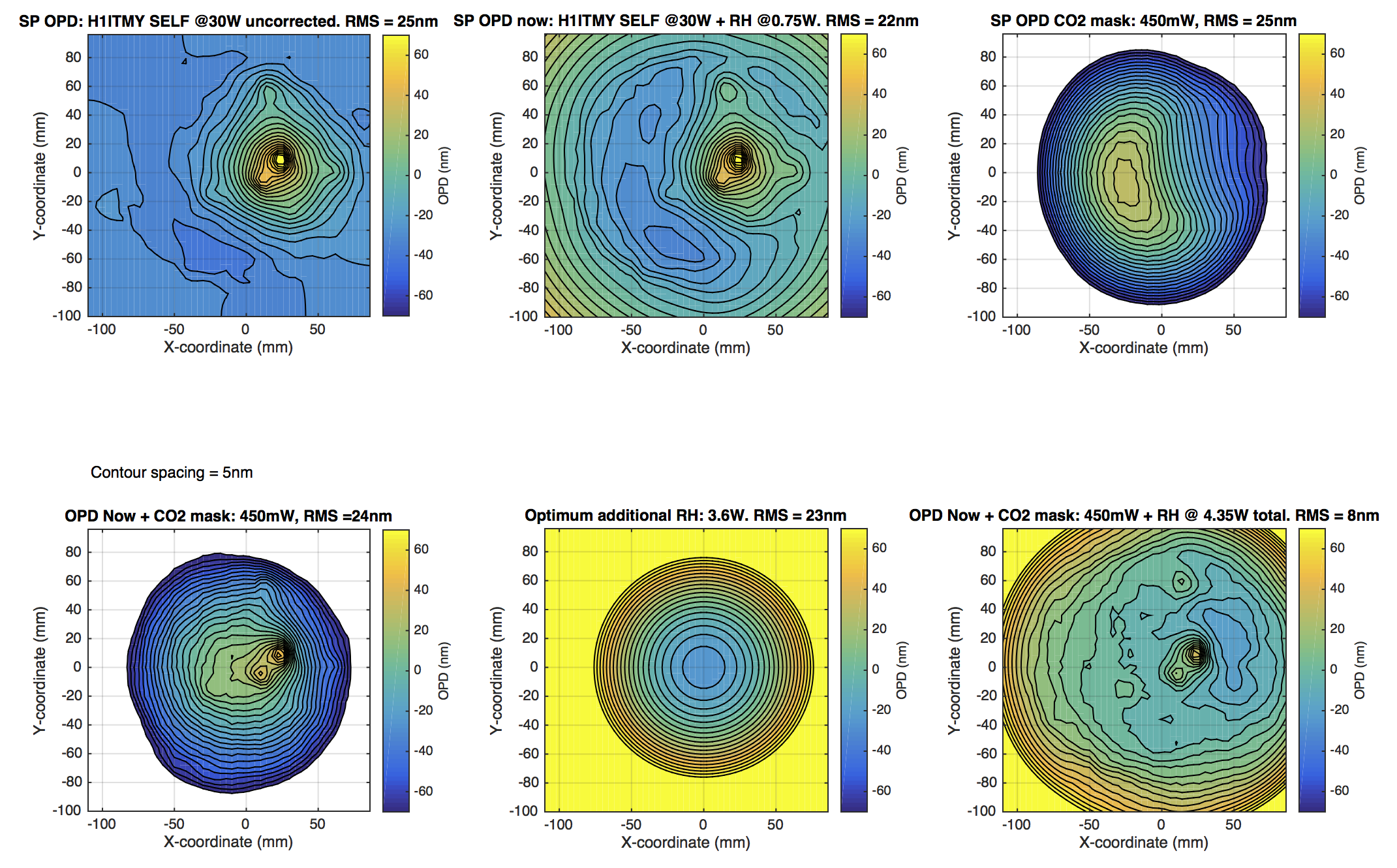
The following is a short summary of an approach to commissioning the H1 ITMY CO2 mask, D1900030. The purpose of the mask is to reduce the scattering of sidebands into higher order spatial modes. However, when the mask is simply applied by itself, it creates a strong positive quadratic lens. A combination of the ITMY RH, ITMX CO2 central heating and ITMX RH must be used to minimize the overall effect of the COMMON & DIFFERENTIAL MICH lenses and the COMMON and DIFFERENTIAL ITM curvatures.

First Step: Mask application to reduce HOM and maintain current quadratic lens in ITMY 

The application of the mask is illustrated in the attached PDFs. An example of the application is shown here:

Note that (a) the color scales have been set to the same level [-70, 70]nm for comparison between different plots [so there is some saturation in some of the plots], (b) contours are set to 5nm spacing in all plots, (c) DC levels have been subtracted from each image so that the Gaussian weighted mean value is 0nm.

Once this step has been applied, the ITMY substrate lens should be same as it currently is. This will maintain the COMMON and DIFFERENTIAL MICH lenses. However, the application of ITMY RH will change the ITMY ROC and, hence, the COMMON and DIFF ITM ROC will need to be corrected. Which will be dealt with in step 2.

The attached PDFs show the effect for differing CO2 powers ranging from 50mW to 750mW. The minimum RMS OPD is achieved around 450mW. 


Images attached to this report
Non-image files attached to this report
Comments related to this report
aidan.brooks@LIGO.ORG - 09:17, Tuesday 19 February 2019 (46990)

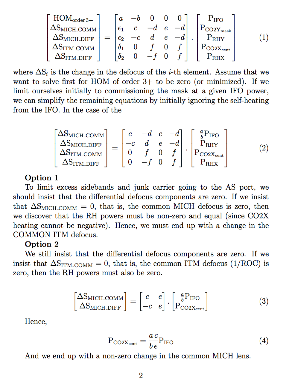
Working on the full matrix description of this: 4 TCS actuators > 4 DOF (COMM/DIFF MICH, COMM/DIFF ITM ROC).

aidan.brooks@LIGO.ORG - 11:12, Tuesday 19 February 2019 (46995)

Somewhat crude matrix analysis of actuation strategies. The effect of interferometer power and the CO2 mask can be seen below. Any actuation strategy that employs this mask will enforce a change in either the COMMON ITM ROC/DEFOCUS and/or the COMMON MICH DEFOCUS.


Images attached to this comment
aidan.brooks@LIGO.ORG - 15:09, Wednesday 20 February 2019 (47035)

I'm working on plotting the time evolution of the RMS value of the OPD once the mask is added. However, as a rough guide (based on (a) some provisional simulations, (b) basic thermal diffusivity calculations), the thermal time constant of the mask is approximately 40 minutes.  This means that the majority of the effect the mask should manifest on this time scale.

Note: this excludes the time constant associated with the RH

aidan.brooks@LIGO.ORG - 13:08, Thursday 21 February 2019 (47058)

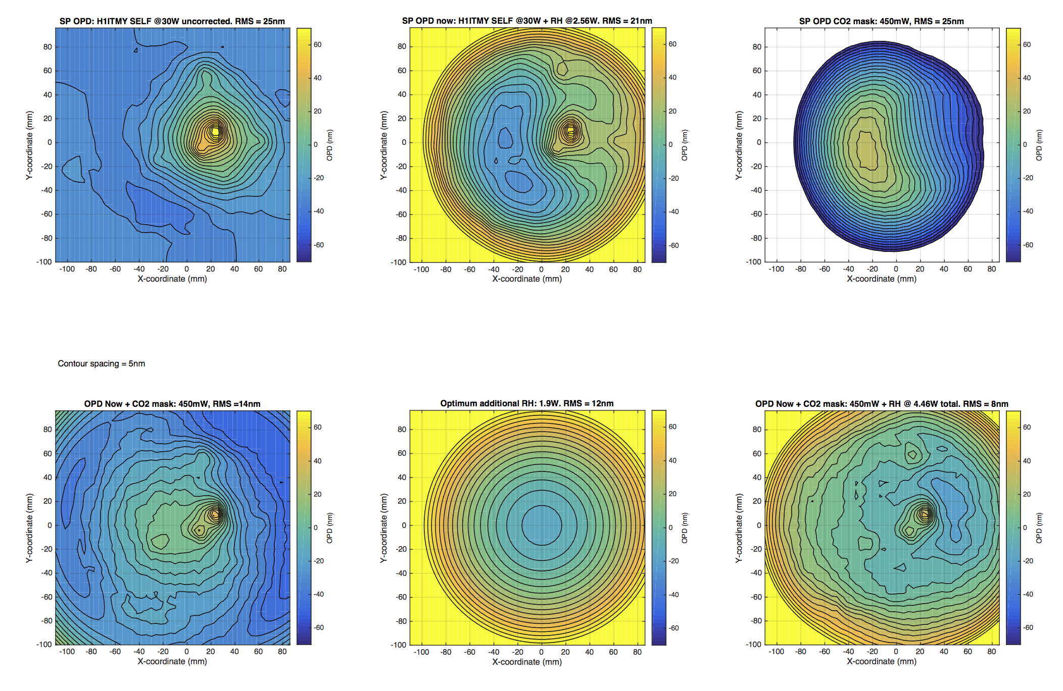
I just discovered that the code used to generate the wavefronts was using the ITMX RH power (~0.78W) rather than the ITMY RH (~2.56W). I'll need to regenerate these plots with the correct RH power.

aidan.brooks@LIGO.ORG - 14:07, Thursday 21 February 2019 (47061)

Here is the updated mask application based on 2.56W into ITMY RH.


Images attached to this comment
Non-image files attached to this comment
H1 CAL (DetChar)
jeffrey.kissel@LIGO.ORG - posted 11:50, Thursday 07 February 2019 - last comment - 10:24, Thursday 21 February 2019(46847)
PCALY Showing Signs of Clipping (Because it's very cold outside again?)
J. Kissel,

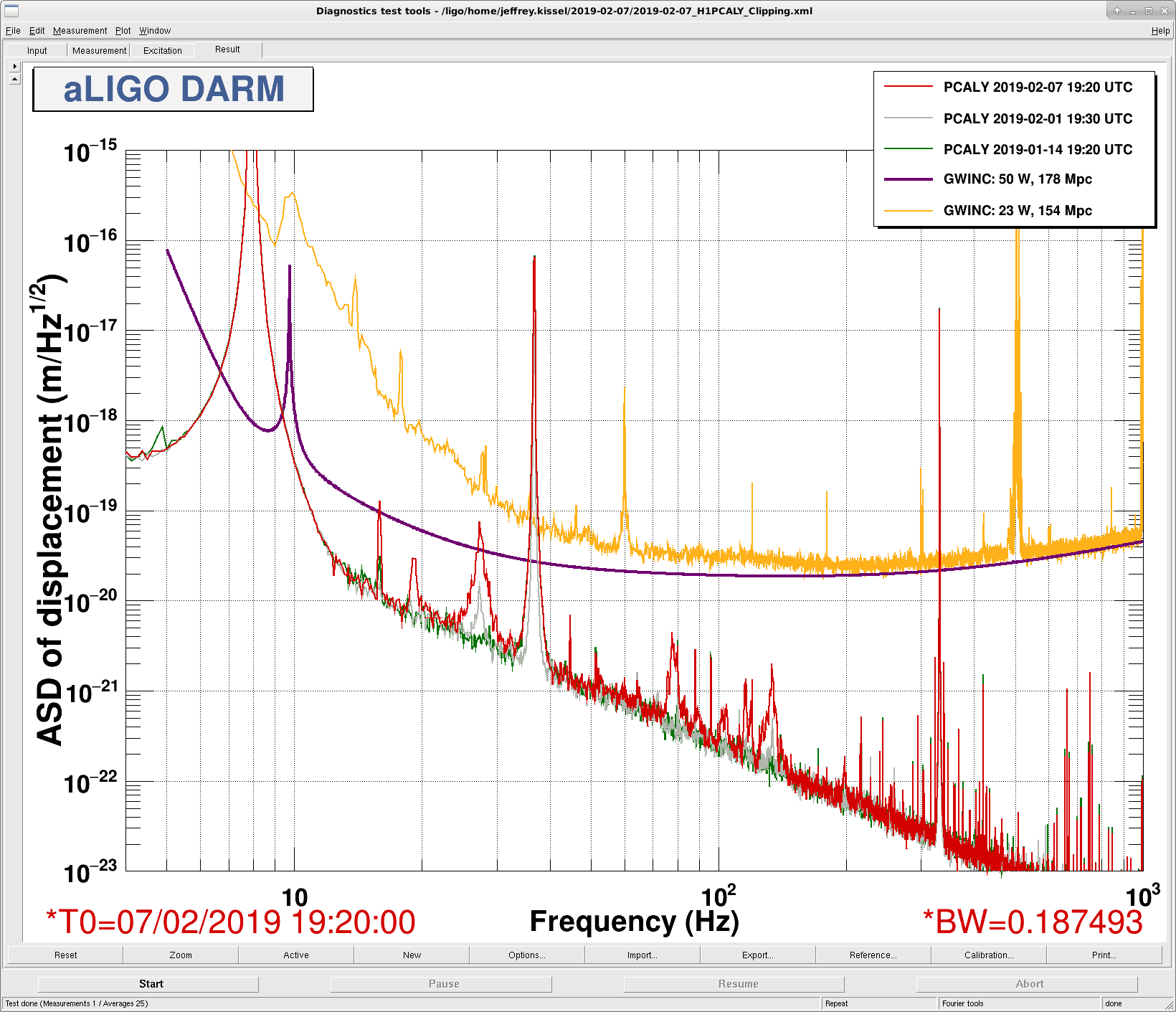
The H1 DARM figure of merit on the wall constantly shows the H1 PCALY PX PD ASD calibrated into displacement, so it's easy to notice when it looks abnormal. Today (and for the past several days), the I've noticed that other peaks in the ASD besides those requested by calibration lines have returned, reminiscent of very-cold winter problems from 2017 (see LHO aLOG 33108, and FRS Tickets 8328 and Integration Issue 8481). Note that temperatures are also quote cold today, in the ~15 deg F range.

This is to notify the PCAL team to investigate.

Also @DetChar, the summary pages for the PCAL system, e.g. the 2019-02-05 PCAL Summary page appears to have a significant flaw in he calibration of the X- and Y-end ASD, off by a factor of about 1000. Further, the last two days on summary have failed, and the "clipping" pages (2019-02-06) are dead and/or a repeat of each other.
Images attached to this report
Comments related to this report
jeffrey.kissel@LIGO.ORG - 10:16, Thursday 21 February 2019 (47055)CAL, FRS
Still clipping. 

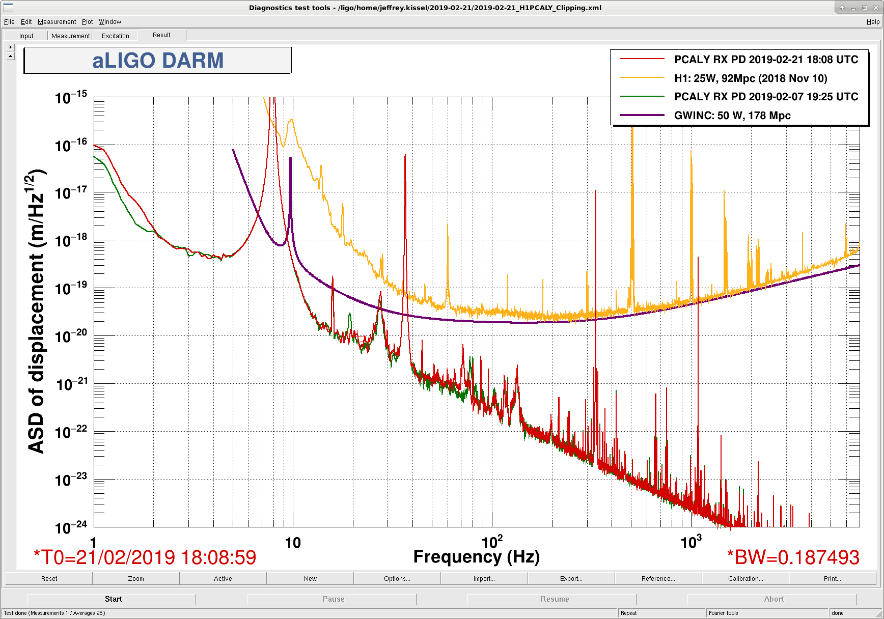
Interestingly (?) a few peaks have changed location. 

The main feature at 27.6 Hz is a little bit worse.

There is no coherence with DARM (even though the ASD reports that the "displacement" is only a bit away from DELTAL EXTERNAL, and there's a completely coincidental feature around that frequency), so this is likely clipping on the RXPD side of things again.
Images attached to this comment
jeffrey.kissel@LIGO.ORG - 10:24, Thursday 21 February 2019 (47056)
Associated with FRS Ticket 12281.
Displaying reports 42981-43000 of 88648.Go to page Start 2146 2147 2148 2149 2150 2151 2152 2153 2154 End